EP0884896A1 - Anzeigevorrichtung mit niedriger Leistungsaufnahme für digitale Bildaufnahmevorrichtung - Google Patents
Anzeigevorrichtung mit niedriger Leistungsaufnahme für digitale Bildaufnahmevorrichtung Download PDFInfo
- Publication number
- EP0884896A1 EP0884896A1 EP98201754A EP98201754A EP0884896A1 EP 0884896 A1 EP0884896 A1 EP 0884896A1 EP 98201754 A EP98201754 A EP 98201754A EP 98201754 A EP98201754 A EP 98201754A EP 0884896 A1 EP0884896 A1 EP 0884896A1
- Authority
- EP
- European Patent Office
- Prior art keywords
- display
- digital image
- image capture
- housing
- capture system
- Prior art date
- Legal status (The legal status is an assumption and is not a legal conclusion. Google has not performed a legal analysis and makes no representation as to the accuracy of the status listed.)
- Withdrawn
Links
Images


Classifications
-
- H—ELECTRICITY
- H04—ELECTRIC COMMUNICATION TECHNIQUE
- H04N—PICTORIAL COMMUNICATION, e.g. TELEVISION
- H04N23/00—Cameras or camera modules comprising electronic image sensors; Control thereof
- H04N23/50—Constructional details
- H04N23/53—Constructional details of electronic viewfinders, e.g. rotatable or detachable
- H04N23/531—Constructional details of electronic viewfinders, e.g. rotatable or detachable being rotatable or detachable
-
- H—ELECTRICITY
- H04—ELECTRIC COMMUNICATION TECHNIQUE
- H04N—PICTORIAL COMMUNICATION, e.g. TELEVISION
- H04N23/00—Cameras or camera modules comprising electronic image sensors; Control thereof
- H04N23/60—Control of cameras or camera modules
- H04N23/63—Control of cameras or camera modules by using electronic viewfinders
Definitions
- LCD liquid crystal
- the present invention solves this problem by providing a low power electronic display (e.g., a nonbacklit LCD display) for a digital image capture device such as a digital camera or a digital camcorder, wherein the low power electronic display uses external light energy produced by an external illumination source for its radiation.
- a low power electronic display e.g., a nonbacklit LCD display
- a digital image capture device such as a digital camera or a digital camcorder
- a first embodiment of the present invention incorporates a retractable low power display which selectively extends from the housing of a digital camera. When not required, the display can be retracted into the housing of the digital camera. When a user requires the display for use as a viewfinder or for the review of previously captured digital images, the display extends or "pops out" of the digital camera housing.
- the display is designed to use external light energy for its radiation, produced by an external illumination source such as the sun, a fluorescent or incandescent lamp, or other suitable illumination means, allowing the user to easily view an image presented on the display without the deleterious battery drain suffered by prior art digital cameras having, for example, backlit LCD displays.
- the low power display of the present invention can be implemented using a wide variety of technologies.
- a nonbacklit transmissive LCD display can be used.
- a diffuser can be employed in conjunction with the transmissive LCD display to provide a more uniform distribution of light energy across the display.
- An antireflective coating can be applied to reduce or eliminate any glare from the viewing surface of the transmissive LCD display.
- a reflective-type LCD display can also be used in the present invention.
- the display uses external light energy produced by an external illumination source for its radiation, thereby greatly extending the life of the batteries used by the digital camera.
- the low power display is pivotally attached to the housing of the digital camera.
- the display can be pivoted to an unobtrusive position on the digital camera.
- the display can be pivoted to a position where it can receive external light energy from an external illumination source.
- the low power display is fixedly attached to the housing of the digital camera, much like a conventional viewfinder, such that a user can look through the digital camera via the display.
- the display receives external light energy from an external source of illumination through the front of the digital camera.
- Digital image data on the display is presented to a user at the back of the digital camera.
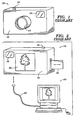
- FIGS. 1 and 2 A conventional digital camera, generally designated as 10, is illustrated in FIGS. 1 and 2.
- the digital camera 10 generally includes a housing 12 enclosing the electronic, sensor, and computer components necessary for the acquisition, storage and display of a plurality of digital images.
- the digital camera 10 further includes a focusing lens arrangement 14, a conventional viewfinder 16, and a "shutter" button 18 for initiating the capture of a scene to be photographed.
- the camera 10 may additionally include a supply of random access memory (RAM) for the temporary storage of captured digital images.
- RAM random access memory
- FIG. 2 A rear perspective view of the digital camera 10 is illustrated in FIG. 2.
- a liquid crystal (LCD) display 22 (color or monochrome) is incorporated into the back of the housing 12.
- the LCD display 22 allows an operator to view a low resolution representation of a captured digital image. This image may be the most recently captured digital image, or a previously captured digital image stored in the RAM or the storage device 20. Also, the LCD display 22 can be used as a viewfinder to frame an image in lieu of, or in conjunction with, viewfinder 16.
- Each captured digital image is stored in high resolution in the RAM and/or on the storage device 20.
- the high resolution digital images are immediately available for viewing, editing and/or processing if, at the time of image capture, the digital camera 10 is tethered to a computer workstation 24 by an appropriate cabling arrangement 26.
- the operator of the digital camera 10 can immediately examine the detail of a captured digital image and, if necessary, reshoot the scene.
- the operator When away from the computer workstation, however, the operator must rely on the low resolution image presented on the LCD display 22 to judge the quality of a captured digital image.
- the digital camera 30 includes a housing 12 enclosing the electronic, sensor, and computer components necessary for the acquisition, storage and display of a plurality of digital images, a focusing lens arrangement (not shown), a viewfinder 16, a button 18 for initiating image capture, and a removable storage device 20.
- the digital camera 30 further includes a retractable, low power LCD display 32 for displaying the images captured by, or stored in, the digital camera 30. Unlike the backlit LCD display 22 used by the digital camera 10 shown in FIG.
- the digital camera 30 does not use backlighting when displaying a captured digital image on the low power LCD display 32. Instead, the low power display 32 is irradiated by external light energy produced by an external illumination source independently of the source (e.g., batteries) powering the digital camera 30.
- an external illumination source independently of the source (e.g., batteries) powering the digital camera 30.
- the low power display 32 is retractable. This is accomplished using a spring-loaded retraction system 34 or equivalent arrangement a manner known in the art.
- the low power display In the retracted position, as indicated in phantom as 32' in FIG. 3, the low power display is located within an enclosure 36 formed in the housing 12 of the digital camera 30.
- the enclosure 36 includes an aperture 38 formed in the top of the housing 12 through which the low power display 32 is retracted or extended.
- the low power display 32 is designed to be displaced between extended and retracted positions as indicated by directional arrow 40 in FIG. 3. In the extended position, the low power display 32 uses external light energy produced by an external source of illumination 42 for its radiation. The external light energy passes through the display from front to back, allowing a user to view a captured digital image 44 on the display. It should be noted that the digital image 44 is displayed in a conventional manner on the low power display 32, but without backlighting.
- FIG. 4 A cross-sectional view of the low power LCD display 32 taken along line 4--4 of FIG. 3 is provided in FIG. 4.
- the low power display 32 includes a housing 46 containing a transmissive LCD imaging unit 48 on which a captured digital image is displayed in a conventional manner.
- a transmissive diffuser 50 is positioned on the front side of the imaging unit 48 to uniformly distribute the light energy received from the external source of illumination 42 across the imaging unit 48.
- An antireflective coating 52 is applied to the glass faceplate 54 on the opposing side of the imaging unit 48 to reduce glare when viewed by a user.
- a diffuser 56 used in a reflective mode can also be used to uniformly distribute the light energy from an external source of illumination 42 across the imaging unit 48.
- the diffuser 56 is pivotally attached to the housing 46 of the display 32 at pivot point 58.
- the diffuser 56 uniformly redirects light energy from an overhead illumination source across the imaging unit 48 of the display 32.
- the diffuser 56 can be repositioned as necessary as depicted by directional arrow 60, depending on the location of the illumination source, to adjust the level of light energy directed toward the display 32.
- the diffuser 56 can be pivotally attached to the housing 12 of the digital camera 30.
- FIG. 6 A digital camera 30 incorporating a low power display 70 in accordance with a second embodiment of the present invention is illustrated in FIG. 6.
- the display 70 is pivotally secured to the top of the housing 12 of the digital camera 30 at pivot point 72.
- the display 70 can be pivoted between a first upright position 74 for the display of digital image data captured by the digital camera 30, and a second position 74'. In the first position 74, the display uses external light energy produced by an external illumination source 42 for its radiation. In the second position 74', the display 70 is positioned flat against the top of the housing 12.
- FIG. 7 A further embodiment according to the present invention is shown in FIG. 7.
- the digital camera 30 includes a low power display 80 which is fixed within the housing 12 of the camera.
- the display 80 has a first side 82 positioned on a front side 12F of the housing 12, and a second side 84 positioned on a rear side 12R of the housing.
- the display 80 uses external light energy provided by an external source of illumination 42 for its radiation. The light energy enters the front side 82 of the display, thereby allowing a user to view digital image data on the second side 84 of the display.
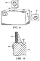
- FIG. 9 A detachable low power display 90 in accordance with the present invention is illustrated in FIG. 9.
- the low power display 90 includes a connector 92 which is removably insertable into a corresponding port 94 formed in housing 12 of the digital camera 30.
- an adequate source of external illumination is not available to a user of the digital camera 30. This may occur, for example, when taking a digital photograph of a scene in a darkened room.
- an auxiliary illumination source is illustrated in FIG. 10.
- the auxiliary illumination source 100 is recessed in the top of the housing 12 in front of the low power display 102.
- the illumination source 100 may be selectively actuated by a user via button 104. Alternately, the illumination source 100 may be automatically activated using a photodetector or the like.
Landscapes
- Engineering & Computer Science (AREA)
- Multimedia (AREA)
- Signal Processing (AREA)
- Studio Devices (AREA)
- Viewfinders (AREA)
Applications Claiming Priority (2)
| Application Number | Priority Date | Filing Date | Title |
|---|---|---|---|
| US871745 | 1986-06-09 | ||
| US87174597A | 1997-06-09 | 1997-06-09 |
Publications (1)
| Publication Number | Publication Date |
|---|---|
| EP0884896A1 true EP0884896A1 (de) | 1998-12-16 |
Family
ID=25358036
Family Applications (1)
| Application Number | Title | Priority Date | Filing Date |
|---|---|---|---|
| EP98201754A Withdrawn EP0884896A1 (de) | 1997-06-09 | 1998-05-26 | Anzeigevorrichtung mit niedriger Leistungsaufnahme für digitale Bildaufnahmevorrichtung |
Country Status (2)
| Country | Link |
|---|---|
| EP (1) | EP0884896A1 (de) |
| JP (1) | JPH11234546A (de) |
Cited By (2)
| Publication number | Priority date | Publication date | Assignee | Title |
|---|---|---|---|---|
| WO2001074052A3 (en) * | 2000-03-27 | 2002-01-31 | Technology Innovations Llc | A machine and method for imaging display output on a copier, scanning device, or fax machine |
| EP1587031A3 (de) * | 2004-04-16 | 2012-09-26 | Sony Corporation | Verfahren und Vorrichtung zur Bildaufnahme |
Families Citing this family (1)
| Publication number | Priority date | Publication date | Assignee | Title |
|---|---|---|---|---|
| KR100421994B1 (ko) * | 2001-05-21 | 2004-03-10 | 삼성전자주식회사 | 촬상장치용 뷰파인더 및 이를 구비한 캠코더 |
Citations (11)
| Publication number | Priority date | Publication date | Assignee | Title |
|---|---|---|---|---|
| JPS5922489A (ja) * | 1982-07-28 | 1984-02-04 | Seiko Epson Corp | テレビジヨン受信機 |
| US4635128A (en) * | 1983-06-29 | 1987-01-06 | Seiko Epson Kabushiki Kaisha | Pocket machinery cabinet |
| JPS62171384A (ja) * | 1986-01-24 | 1987-07-28 | Matsushita Electric Ind Co Ltd | 電子ビユ−フアインダ装置 |
| JPS6399678A (ja) * | 1986-10-15 | 1988-04-30 | Fujitsu General Ltd | ビデオカメラ |
| JPS6399677A (ja) * | 1986-10-15 | 1988-04-30 | Fujitsu General Ltd | ビデオカメラ |
| JPS6449379A (en) * | 1987-08-19 | 1989-02-23 | Seiko Epson Corp | Electronic view finder |
| JPH05122575A (ja) * | 1991-10-29 | 1993-05-18 | Kyocera Corp | ノート形デイジタル電子カメラ |
| JPH05297367A (ja) * | 1992-04-16 | 1993-11-12 | Ricoh Co Ltd | 液晶表示装置及びこの液晶表示装置を用いたビューファインダ |
| JPH08129172A (ja) * | 1994-10-31 | 1996-05-21 | Sony Corp | 表示装置 |
| WO1997001240A1 (en) * | 1995-06-20 | 1997-01-09 | Thomson Consumer Electronics, Inc. | Back lit electronic viewfinder |
| JPH0946564A (ja) * | 1995-08-02 | 1997-02-14 | Sony Corp | 液晶モニタ付きビデオカメラ装置 |
-
1998
- 1998-05-26 EP EP98201754A patent/EP0884896A1/de not_active Withdrawn
- 1998-06-05 JP JP10174157A patent/JPH11234546A/ja active Pending
Patent Citations (11)
| Publication number | Priority date | Publication date | Assignee | Title |
|---|---|---|---|---|
| JPS5922489A (ja) * | 1982-07-28 | 1984-02-04 | Seiko Epson Corp | テレビジヨン受信機 |
| US4635128A (en) * | 1983-06-29 | 1987-01-06 | Seiko Epson Kabushiki Kaisha | Pocket machinery cabinet |
| JPS62171384A (ja) * | 1986-01-24 | 1987-07-28 | Matsushita Electric Ind Co Ltd | 電子ビユ−フアインダ装置 |
| JPS6399678A (ja) * | 1986-10-15 | 1988-04-30 | Fujitsu General Ltd | ビデオカメラ |
| JPS6399677A (ja) * | 1986-10-15 | 1988-04-30 | Fujitsu General Ltd | ビデオカメラ |
| JPS6449379A (en) * | 1987-08-19 | 1989-02-23 | Seiko Epson Corp | Electronic view finder |
| JPH05122575A (ja) * | 1991-10-29 | 1993-05-18 | Kyocera Corp | ノート形デイジタル電子カメラ |
| JPH05297367A (ja) * | 1992-04-16 | 1993-11-12 | Ricoh Co Ltd | 液晶表示装置及びこの液晶表示装置を用いたビューファインダ |
| JPH08129172A (ja) * | 1994-10-31 | 1996-05-21 | Sony Corp | 表示装置 |
| WO1997001240A1 (en) * | 1995-06-20 | 1997-01-09 | Thomson Consumer Electronics, Inc. | Back lit electronic viewfinder |
| JPH0946564A (ja) * | 1995-08-02 | 1997-02-14 | Sony Corp | 液晶モニタ付きビデオカメラ装置 |
Non-Patent Citations (9)
| Title |
|---|
| PATENT ABSTRACTS OF JAPAN vol. 008, no. 107 (E - 245) 19 May 1984 (1984-05-19) * |
| PATENT ABSTRACTS OF JAPAN vol. 012, no. 013 (E - 573) 14 January 1988 (1988-01-14) * |
| PATENT ABSTRACTS OF JAPAN vol. 012, no. 337 (E - 657) 12 September 1988 (1988-09-12) * |
| PATENT ABSTRACTS OF JAPAN vol. 013, no. 248 (E - 770) 9 June 1989 (1989-06-09) * |
| PATENT ABSTRACTS OF JAPAN vol. 017, no. 494 (E - 1428) 7 September 1993 (1993-09-07) * |
| PATENT ABSTRACTS OF JAPAN vol. 018, no. 096 (P - 1694) 16 February 1994 (1994-02-16) * |
| PATENT ABSTRACTS OF JAPAN vol. 096, no. 009 30 September 1996 (1996-09-30) * |
| PATENT ABSTRACTS OF JAPAN vol. 097, no. 006 30 June 1997 (1997-06-30) * |
| WEN-HSIN CHAN ET AL: "VIDEO CCD BASED PORTABLE DIGITAL STILL CAMERA", IEEE TRANSACTIONS ON CONSUMER ELECTRONICS, vol. 41, no. 3, 1 August 1995 (1995-08-01), pages 455 - 459, XP000539491 * |
Cited By (2)
| Publication number | Priority date | Publication date | Assignee | Title |
|---|---|---|---|---|
| WO2001074052A3 (en) * | 2000-03-27 | 2002-01-31 | Technology Innovations Llc | A machine and method for imaging display output on a copier, scanning device, or fax machine |
| EP1587031A3 (de) * | 2004-04-16 | 2012-09-26 | Sony Corporation | Verfahren und Vorrichtung zur Bildaufnahme |
Also Published As
| Publication number | Publication date |
|---|---|
| JPH11234546A (ja) | 1999-08-27 |
Similar Documents
| Publication | Publication Date | Title |
|---|---|---|
| US7557851B2 (en) | Portable terminal equipment | |
| US7023467B2 (en) | Photocard that is inserted into a non-digital camera to enable the non-digital camera to take digital photographic images | |
| US8023029B2 (en) | Digital camera-projector hybrid | |
| US5452000A (en) | Apparatus for electronic photography using a conventional film camera | |
| JP2000502555A (ja) | プリンティング能力を有する電子スチルカメラ | |
| US6339447B1 (en) | Image sensing apparatus | |
| JP4394183B2 (ja) | ディジタル電子スチル・カメラおよびディジタル電子スチル・カメラに着脱自在なメモリ・カード | |
| US5315334A (en) | Liquid crystal finder/projector for video camera | |
| WO1999053374A1 (en) | Instant printer, printing method using the same, combination printer/electronic still camera system | |
| EP0884896A1 (de) | Anzeigevorrichtung mit niedriger Leistungsaufnahme für digitale Bildaufnahmevorrichtung | |
| JP3919321B2 (ja) | 撮像装置 | |
| JPH08242398A (ja) | 撮像装置 | |
| KR20020059126A (ko) | 휴대용 디지털 현미경, 이를 이용한 피부 진단 시스템 및이를 장착하는 씨에프 타입의 씨씨디 카메라 | |
| US5164834A (en) | Camera having a liquid crystal view finder | |
| US7092627B2 (en) | Shooting system and silver-salt camera | |
| JP3093252B2 (ja) | 撮像装置およびアダプタ装置 | |
| JP2000162576A (ja) | 液晶表示装置およびそれを用いたデジタルカメラ | |
| US6516156B2 (en) | Camera having liquid crystal display | |
| JPH09322045A (ja) | 電子ルーペ | |
| CN222776262U (zh) | 一种相机图传机构 | |
| US7533999B2 (en) | Auxiliary lighting device of camera | |
| JP3902856B2 (ja) | 電子カメラ | |
| JPH03163965A (ja) | 電子カメラ | |
| JP3296792B2 (ja) | デジタルカメラ | |
| JP3479561B2 (ja) | 電子的ビューアおよびフイルム・キャリア |
Legal Events
| Date | Code | Title | Description |
|---|---|---|---|
| PUAI | Public reference made under article 153(3) epc to a published international application that has entered the european phase |
Free format text: ORIGINAL CODE: 0009012 |
|
| AK | Designated contracting states |
Kind code of ref document: A1 Designated state(s): AT BE CH CY DE DK ES FI FR GB GR IE IT LI LU MC NL PT SE |
|
| AX | Request for extension of the european patent |
Free format text: AL;LT;LV;MK;RO;SI |
|
| RAP1 | Party data changed (applicant data changed or rights of an application transferred) |
Owner name: AGFA CORPORATION |
|
| RAP1 | Party data changed (applicant data changed or rights of an application transferred) |
Owner name: AGFA CORPORATION |
|
| 17P | Request for examination filed |
Effective date: 19990616 |
|
| AKX | Designation fees paid |
Free format text: BE DE FR GB |
|
| STAA | Information on the status of an ep patent application or granted ep patent |
Free format text: STATUS: THE APPLICATION HAS BEEN WITHDRAWN |
|
| 18W | Application withdrawn |
Withdrawal date: 20001219 |