EP0885076B1 - Gestaffelte matrize verfahren und vorrichtung zum einhalsen von dosen - Google Patents
Gestaffelte matrize verfahren und vorrichtung zum einhalsen von dosen Download PDFInfo
- Publication number
- EP0885076B1 EP0885076B1 EP97945597A EP97945597A EP0885076B1 EP 0885076 B1 EP0885076 B1 EP 0885076B1 EP 97945597 A EP97945597 A EP 97945597A EP 97945597 A EP97945597 A EP 97945597A EP 0885076 B1 EP0885076 B1 EP 0885076B1
- Authority
- EP
- European Patent Office
- Prior art keywords
- necking
- container
- die
- tapered
- cylindrical
- Prior art date
- Legal status (The legal status is an assumption and is not a legal conclusion. Google has not performed a legal analysis and makes no representation as to the accuracy of the status listed.)
- Expired - Lifetime
Links
- 238000000034 method Methods 0.000 title claims description 14
- 125000006850 spacer group Chemical group 0.000 claims abstract description 21
- 229910052751 metal Inorganic materials 0.000 claims description 3
- 239000002184 metal Substances 0.000 claims description 3
- 238000002407 reforming Methods 0.000 claims 1
- 230000008569 process Effects 0.000 description 7
- 229910000831 Steel Inorganic materials 0.000 description 3
- 229910052782 aluminium Inorganic materials 0.000 description 3
- XAGFODPZIPBFFR-UHFFFAOYSA-N aluminium Chemical compound [Al] XAGFODPZIPBFFR-UHFFFAOYSA-N 0.000 description 3
- 239000012530 fluid Substances 0.000 description 3
- 239000010959 steel Substances 0.000 description 3
- 229940037003 alum Drugs 0.000 description 2
- 235000013405 beer Nutrition 0.000 description 2
- 230000006872 improvement Effects 0.000 description 2
- 230000007246 mechanism Effects 0.000 description 2
- 239000000443 aerosol Substances 0.000 description 1
- 230000000712 assembly Effects 0.000 description 1
- 238000000429 assembly Methods 0.000 description 1
- 235000013361 beverage Nutrition 0.000 description 1
- 235000014171 carbonated beverage Nutrition 0.000 description 1
- 230000008859 change Effects 0.000 description 1
- 230000001143 conditioned effect Effects 0.000 description 1
- 239000000945 filler Substances 0.000 description 1
- 239000000203 mixture Substances 0.000 description 1
- 230000004048 modification Effects 0.000 description 1
- 238000012986 modification Methods 0.000 description 1
- 238000004806 packaging method and process Methods 0.000 description 1
- 230000009467 reduction Effects 0.000 description 1
- 239000007787 solid Substances 0.000 description 1
- 230000007704 transition Effects 0.000 description 1
- 230000037303 wrinkles Effects 0.000 description 1
Images



Classifications
-
- B—PERFORMING OPERATIONS; TRANSPORTING
- B21—MECHANICAL METAL-WORKING WITHOUT ESSENTIALLY REMOVING MATERIAL; PUNCHING METAL
- B21D—WORKING OR PROCESSING OF SHEET METAL OR METAL TUBES, RODS OR PROFILES WITHOUT ESSENTIALLY REMOVING MATERIAL; PUNCHING METAL
- B21D51/00—Making hollow objects
- B21D51/16—Making hollow objects characterised by the use of the objects
- B21D51/26—Making hollow objects characterised by the use of the objects cans or tins; Closing same in a permanent manner
- B21D51/2615—Edge treatment of cans or tins
-
- B—PERFORMING OPERATIONS; TRANSPORTING
- B21—MECHANICAL METAL-WORKING WITHOUT ESSENTIALLY REMOVING MATERIAL; PUNCHING METAL
- B21D—WORKING OR PROCESSING OF SHEET METAL OR METAL TUBES, RODS OR PROFILES WITHOUT ESSENTIALLY REMOVING MATERIAL; PUNCHING METAL
- B21D51/00—Making hollow objects
- B21D51/16—Making hollow objects characterised by the use of the objects
- B21D51/26—Making hollow objects characterised by the use of the objects cans or tins; Closing same in a permanent manner
Definitions
- This invention relates to smooth die-necked containers and to the method and apparatus for necking such containers. More particularly, the invention is an improvement over the method and apparatus which is described in U.S. Patent Nos. 4,774,839 (nearest state of the art) and 5,497,900.
- two-piece cans are the most common type of metal containers used in the beer and beverage industry and also are used for aerosol and food packaging. They are usually formed of aluminum or tin-plated steel.
- the two-piece can consists of a first cylindrical can body portion having an integral bottom end wall and a second, separately-formed, top end panel portion which, after the can has been filled, is double-seamed thereon to close the open upper end of the container.
- containers used for beer and carbonated beverages have an outside diameter of 5,08 - 27,94/40,64 cm (2 - 11/16 inches) (referred to as a 211-container) and are reduced to open end diameters of (a) 5,08 - 22,86/40,64 cm (2 - 9/16 inches) (referred to as a 209-neck) typically in a single-necking operation for a 209 end; or, (b) 2 - (7.5)/16 (referred to as a 207.5 neck) typically in a double-necking operation for a 207.5 end; or, (c) 2 - 6/16 (referred to as a 206-neck) in a smooth triple- or quad-necking operation for a 206 end.
- Smaller diameter ends can be used, e.g., 204, 202, 200 or smaller. Further, different can fillers use cans with varying neck size. Hence, it is very important for the can manufacturer to quickly adapt its necking machines and operations from one neck size to another.
- the apparatus for carrying out the die necking process comprises a plurality of turret assemblies with an upper and a lower turret portion.
- the upper turret portion is slidably positionable on a central drive shaft, and can be secured in an adjusted position by a wedge mechanism to accommodate containers of different heights.
- the process is carried out by performing a number of die necking sequences, whereby each of the die necking operations partially overlap, and therefore part of the previously-formed portion is reformed in each sequence.
- the necking die of the necking apparatus contacts the entire surface of the already tapered portion of the container.
- JP-A-6254640 a multi-process die system tool is described for forming a smooth necked-in part on a container.
- the shape of the necking die is such that it has a projecting curved surface - as necking portion of the die - and a guide surface.
- the curved surface of the tool is brought into contact with the end surface of the necked-in portion formed in the previous necking operation, and therefore, reforms also part of the previously formed already necked-in portion.
- each of the die necking operations partially overlaps and reforms only a part of a previously-formed portion to produce a necked-in portion on the end of the cylindrical side wall until the necked-in portion extends the desired length.
- This process produces a smooth, tapered annular wall portion between the cylindrical side wall and the reduced diameter cylindrical neck portion.
- the tapered annular wall portion which has arcuate portions on either end may be characterized as the necked-in portion or taper between the cylindrical side wall and the reduced diameter neck.
- the cylindrical neck merges with the cylindrical side wall through a generally smoothly tapered neck portion.
- the tapered neck portion between the cylindrical neck portion and the cylindrical container side wall initially is defined by a lower, generally arcuate segment having a relatively large internal curvature at the upper end of the cylindrical side wall and an upper, generally arcuate segment having a relatively large external curvature at the lower end of the reduced cylindrical neck.
- a further tapered portion is then formed at the open end and is forced downwardly while the cylindrical neck is further reduced.
- the further tapered portion freely integrates with the second arcuate segment which is reformed and the tapered portion is extended. This process is repeated sequentially until the cylindrical neck is reduced to the desired diameter and a smoothly tapered necked-in portion is formed on the end of the side wall. In each necking operation, the tapered portion is not constrained by the die and is freely formed without regard to the specific dimensions of the die transition zone.
- the container that is formed by the above die necking process has an aesthetically pleasing appearance, greater strength and crush resistance, and is devoid of the scratches or wrinkles in the neck produced in the spin necking operation.
- Each container necking operation is preferably performed in a necking module consisting of a turret which is rotatable about a fixed vertical axis.
- Each turret has a plurality of identical exposed necking substations on the periphery thereof with each necking substation having a stationary necking die, a form control member reciprocable along an axis parallel to the fixed axis for the turret, and a platform being movable by cams and cam followers, as also explained in U.S. Patent No. 4,519,232.
- the second or upper arcuate segment CR in Figures 6-11 of the '839 and '900 patents which is the upper part of the necked-in portion, is reformed in each subsequent necking operation while the tapered portion is enlarged.
- the first arcuate segment CA while not being positively reformed by the die, will have a change in its radius of curvature due to a free forming resulting from the inherent spring back characteristics of the metal.
- the dies in the third and fourth operations have flat tapered surfaces T but the tapered wall segment CT is not formed in the container until the fifth and sixth necking operations. This is believed to result from the free forming of the necked-in portion rather than conforming the necked-in portion to the die.
- each die reforms only an upper portion of the tapered neck, the die engages substantially the entire outer surface of the tapered neck as the container is moved axially to its uppermost position.
- the tapered neck portion which is formed by each die therefore forms an included angle with the axis of the container which is substantially the same as the included angle between the die and the axis of the container.
- the invention spaces or staggers the dies farther away from the container supports so that the necking portion of each die engages only the cylindrical portion of the neck and does not engage the tapered portion of the neck.
- the dies of successive necking modules are preferably staggered or cascaded, i.e., each die is spaced a greater distance from the container support than the die of the previous module.
- the staggered dies reduce the axial loads on the container and thereby reduce pleating of the container wall and reduce the tendency of the bottom of the container to become squat or deformed.
- the staggered dies also enable better control of container height and flange width.
- Figure 1 illustrates one of the necking modules of a necking apparatus of the type which is described in U.S. Patent Nos. 4,774,839 and 5,497,900 but which has been modified in accordance with the invention. Except for the modifications which are described herein, the necking apparatus of this invention is substantially identical to the necking apparatus of the '839 and '900 patents. For the sake of clarity like reference numerals will be used for like parts.
- the apparatus illustrated in Figure 1 is known as a 5811-2 necker machine.
- Each necking module of the necking apparatus includes a frame 50 and a rotary turret assembly 70 that holds a plurality of identical necking substations 72 around the periphery thereof.
- Figure 1 illustrates two of the substations 72a and 72b.
- the module frame 50 includes a base 51 and lower and upper frame members 52 and 54 which are interconnected by columns 56.
- a lower turret frame 74 and an upper turret frame 76 are supported on a central drive shaft 78 that extends through openings in frame members 52 and 54.
- Turret assembly 70 is rotatably supported on the frame members by bearings 84a and 84b.
- the upper turret frame 76 is slidable axially on drive shaft 78 and is secured in the desired axial position by a collar 88.
- Figure 2 discloses in greater detail necking substation 72 comprising a lower container-lifting portion, generally indicated at 100, and an upper forming or necking portion, generally indicated at 102.
- the container-lifting portion 100 includes an outer cylindrical member or sleeve 108 that has a generally circular opening 110 with a ram or piston 112 reciprocably movable in the opening 110.
- the lower end of ram 112 has a cam follower 116 (see Figure 1) which rides on an upper exposed camming surface of a face cam 118 supported on lower frame member 52.
- the upper end of ram 112 has a container supporting platform 120 secured thereto by fastener means 122.
- the support platform or container support means has an inner upwardly-arcuate extension 124 for engaging the inner lower surface of container 116.
- Ram 112 cooperates with sleeve 108 to provide both a fluid centering mechanism and to bias the cam followers 116 into engagement with the cam 118, as described in more detail in U.S. Patent No. 4,519,232.
- the cam 118 essentially comprises a fixedly-mounted ring circumferentially seated on lower frame member 52.
- the cam is of selected height and configuration and aligned with the lower end of the substations 72 to control the upward and downward movement of the piston 112 and hence of the container 16 as the turret is rotated on the fixed frame 50. Since the cam followers 116 are biased into engagement with the cam 118, the configuration of the camming surface of the face cam will dictate the position of the container 16, as will be described later.
- the upper necking portion 102 includes a necking die element 130 that is secured to a hollow cylinder 132 by means of a threaded cap 134.
- the cylinder 132 has an axial opening 136 in which a hollow plunger or shaft 137 is reciprocally mounted.
- a cam follower 138 (see Figure 1) is mounted on the upper end of shaft 137 and rollably abuts on an exposed camming surface of a fixed upper face cam 139 secured to upper frame member 54.
- Plunger 137 and cam follower 138 are maintained in engagement with the cam 139 by fluid pressure which also centers the shaft 137 in the opening 136, all as explained in U.S. Patent No. 4,519,232.
- the lower end of plunger 137 supports a form control member 140, as described in the '839 and '900 patents.
- the plunger 137 and the form control member 140 have an opening 141 for introducing pressurized air into the container during the necking operation, as will be explained later.
- shaft 78 is caused to rotate about a fixed axis on the stationary frame 50.
- Containers 16 are moved onto the platform 120 and into engagement with arcuate extension 124 when the lower lifting portion is in the lower-most position, shown in substation 72a at the left-hand side of Figure 1.
- the configuration of the lower cam 118 is such that the container is moved up into the die 130 as the shaft 78 is rotated, and the upper open end of the container is thereby incremently reformed.
- pressurized air is introduced into the container from a source (not shown) through opening 141.
- the upper cam 139 is configured to allow the form control member 140 to move upwardly based on the configuration of the cam.
- shaft 137 including the form control member 140 is biased upwardly by fluid pressure, and will move upwardly as the turret assembly rotates.
- the cams 118 and 139 are configured to return the platform 120 and form control member 140 to their lower-most positions at substantially matched speeds while the necked container is removed from the die. During this downward movement, the pressurized air in the container will force the container from the die onto the platform 120.
- Containers 16 are continually being introduced onto platform 120, processed, and removed as described in the '839 and '900 patents.
- a container is necked to have a smaller opening by utilizing a plurality of necking modules.
- necking modules ten different necking operations and one flanging operation are performed on the neck of the container.
- An upper part of the necked-in or inwardly-tapered portion is reshaped during each of the necking operations.
- a small overlap is created between a previously necked-in portion while the overall necked-in portion is extended and axially enlarged and small segments of reduction are taken so that the various operations blend smoothly into the finished necked-in portion.
- the resultant necked-in portion has a rounded shoulder on the end of the cylindrical side wall which merges with an inwardly-tapered annular straight segment through an arcuate portion.
- the opposite end of the annular straight segment merges with the reduced cylindrical neck through a second arcuate segment.
- the tapered necking portion of the die of each necking substation contacts the entire tapered neck of the container when the container is in its uppermost position.
- the tapered portion of the die does not contact the entire neck of the container but contacts only an upper portion of the neck.
- the necking portion of the die contacts only the reduced-diameter cylindrical portion and adjacent forming radius of the neck and not the tapered portion of the neck. Axial loads on the container are thereby reduced, pleating of the container is reduced, and there is less likelihood that the bottom of the container will be squat or deformed.
- the invention also provides better control of the height variation of the necked container and of the width of the flange.
- Reducing the amount of engagement between the dies and the neck of the container is accomplished by staggering or cascading the spacing between the dies of the necking substation relative to the container supporting platforms 120.
- the necking module of the '839 and '900 patents are modified by removable spacers 310 for a 5811-2 necker machine which are positioned between the collars 58 on the columns 56 and the upper frame member 54.
- the axial position of the upper turret frame 76 along the drive shaft 78 can thereby be varied in order to control the spacing of the dies 130 relative to the container support platforms 120.
- the axial dimension of the spacers of each substation is selected so that when the container is in its uppermost position in the die, the tapered necking portion of the die does not engage the entire neck of the container.
- the tapered necking portion of the die engages only the reduced-diameter cylindrical portion and the adjacnet forming radius of the neck which extends above the tapered portion of the neck (compare Figure 6 with the right sides of Figures 7-11 of the '839 and '900 patents).
- Figure 3 illustrates the first necking operation which is performed in the first necking module.
- the left side of Figure 3 shows a container 16 being moved upwardly into a necking die 130a.
- the necking die has a first cylindrical wall portion 203, a tapered necking portion 204, and a second cylindrical wall portion 205.
- the first cylindrical wall portion 203 has a diameter approximately equal to the external diameter of the container 16 with a clearance of about 0,152 mm (0.006 inch).
- the second cylindrical wall portion 205 has a reduced diameter equal to the external diameter of the reduced neck that is being formed in the first necking operation.
- the diameter of the container neck is reduced, and a tapered neck portion 211 is formed on the container body between the cylindrical side wall 210 and the reduced cylindrical neck portion 212.
- the diameter of the neck is reduced only a very small amount, e.g., about 1,753 mm (0.069 inch), while the portion of the container to be necked is conditioned for subsequent operations.
- FIG. 4 illustrates a subsequent necking operation which is performed in one of the subsequent necking modules.
- a necking die 130b includes a first cylindrical surface 203, having a diameter approximately equal to the center diameter of the container, a tapered neck portion 204, and a reduced diameter cylindrical surface 205. As the container 16 is moved upwardly, the cylindrical neck portion 212 engages the tapered necking portion 204 of the die and is forced radially inwardly.
- the container 210 is shown in its uppermost position in the right hand side of Figure 4 and in the enlarged view of Figure 6.
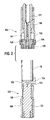
- the tapered neck portion 211 of the container is spaced below the tapered necking portion 204 of the die by the spacers 310, and the necking portion 204 does not engage the tapered neck portion 211 of the container.
- the necking portion 204 of the die may contact the forming radius 213 ( Figure 6) which joins the tapered portion 211 and the cylindrical neck 212 of the container. More particularly, the radiused portion 206 of the die engages and reforms the upper portion of the neck as the container moves upwardly.
- the axial dimension of the gap between the tapered necking portion 204 of the die and the tapered neck portion 211 of the container is exaggerated in Figures 4 and 5 for the purpose of illustration. The actual gap is more accurately illustrated in the enlarged view of Figure 6.
- the axial dimension of the gap in the preferred embodiment of the invention is only about 0,127 mm (0.005 inch).
- the tapered necking portion 204 of the die forms an angle A with the longitudinal axis of the container, and the tapered neck 211 of the container forms an angle B with the longitudinal axis. In the preferred embodiment the angle A was 33° and the angle B was 30°3'47".
- the tapered necking portion 204 of the die does not engage the tapered neck 211 of the container, the upper portion of the necked-in portion of the container, consisting of the tapered portion 211 and the cylindrical portion 212, is reformed, and the length of the tapered neck 211 is increased.
- FIG. 5 illustrates a necking operation subsequent to the necking operation illustrated in Figure 4.
- a necking die 130c includes a cylindrical side wall 203 having a diameter approximately equal to the outer diameter of the container 16, a tapered necking portion 204, and a second cylindrical wall portion 205.
- the container 16 includes a tapered neck portion 211 and a cylindrical neck portion 212.
- the cylindrical neck 212 of the container engages the tapered necking portion 204 of the die and is reformed, thereby lengthening the tapered neck 211 of the container.
- the spacers 310 prevent the tapered necking portion 204 of the die from engaging the tapered neck 211 of the container when the container is in its uppermost position, and only the cylindrical neck portion 212 and the forming radius 213 ( Figure 6) of the container is engaged by the necking portion 204 of the die.
- Figure 7 illustrates the 10 necking operations which are performed by the apparatus described in the '839 and '900 patents to form a 202 size neck on a 211 container.
- the container has a cylindrical side wall 312, a smooth tapered neck portion 314, a cylindrical neck 316, and a flange 318.
- the tapered neck 314 forms an included angle of about 33° relative to a line L which extends parallel to the longitudinal axis of the container.
- the necking portion 204 of each of the necking dies also has an angle of about 33° relative to the longitudinal axis of the die.
- Figure 8 illustrates the 10 necking operations which are performed on an apparatus which is modified in accordance with the invention by adding the spacers 310 for 5811-2 necker machine in order to maintain the necking portion 204 of each die above the tapered neck of the container when the container is in its uppermost position in the die.
- the container similarly includes a cylindrical side wall 320, a smooth tapered neck 322, a cylindrical neck 324, and a flange 326.
- the angle of the tapered neck relative to the line L which extends parallel to the axis of the container is less than the angle of the tapered neck 314 in Figure 6.
- the necking portions of the dies which were used to form the container of Figure 7 formed an angle of 33° relative to the axis of the dies, the angle of the tapered neck 322 was only about 30°3'47".
- Figure 9 compares the tapered neck of Figure 7 (shown in dashed outline, with the tapered neck of Figure 8, shown in solid outline). Although the diameter of the cylindrical wall portions of the two containers and the diameters of the cylindrical neck portions of the two cans are the same, the angle of the tapered neck portion 322 is less than the angle of the tapered neck portion 314.
- Table 1 illustrates specific spacer thicknesses for 10 necking operations for forming a 202 size neck on a 211 diameter container.
- One of the containers was aluminum and had a can height of 12,2 cm (4.812 inch) and a capacity of 340 g (12 ounces).
- the other container was aluminum and had a can height of 11,52 cm (4.535 inch) and a capacity of 33 centiliters.
- Spacers having different thicknesses were used in four different style necking machines, designated as 588, 589, 5811, and 5811-2 neckers. After the first necking operation, the thickness of the spacers increased by 0,127 mm (0.005 inch) for each operation in order to accommodate the increased length of the smooth tapered neck of the container.
- Table 2 lists the dimensions for the spacers used in 14 necking operations to produce a 202 size neck on a 211 diameter steel can having a can height of 11,52 cm (4.535 inch) and a capacity of 33 cl. After the second necking operation, the thickness of the spacers increased 0,127 mm (0,005 inch) for each operation.
Landscapes
- Engineering & Computer Science (AREA)
- Mechanical Engineering (AREA)
- Shaping Metal By Deep-Drawing, Or The Like (AREA)
- Containers Having Bodies Formed In One Piece (AREA)
- Blow-Moulding Or Thermoforming Of Plastics Or The Like (AREA)
- Steering Control In Accordance With Driving Conditions (AREA)
- Sealing Battery Cases Or Jackets (AREA)
- Lining Or Joining Of Plastics Or The Like (AREA)
- Perforating, Stamping-Out Or Severing By Means Other Than Cutting (AREA)
- Adornments (AREA)
Claims (6)
- Einschnürvorrichtung zum Herstellen eines weich nach innen gerichtet zerkleinerten eingeschnürten Abschnitts nahe eines offenen Endes eines Behälters, welche eine im allgemeinen zylindrische Seitenwand aufweist, umfassend:dadurch gekennzeichnet, dasseine Vielzahl von Einschnürmodulen, wobei jedes der Einschnürmodule einen Modulrahmen (50) und einen Revolver (70) enthält, der drehbar auf dem Modulrahmen (50) zur Drehung um eine fixierte Achse montiert ist, wobei der Revolver (70) der Module eine Antriebswelle (78) enthält, die drehbar auf dem Modulrahmen (50) montiert ist,einen oberen Revolverrahmen (76), der auf der Antriebswelle (78) montiert ist, und in der gewünschten axialen Position darauf durch eine Einfassung (88) befestigt ist; einen unteren Revolverrahmen (74), der auf der Antriebswelle (78) montiert ist, und eine Vielzahl von Einschnürunterstationen (72), die auf dem oberen und unteren Revolverrahmen (74, 76) montiert sind, wobei jede der Einschnürunterstationen (72) enthält,einen ringförmigen Einschnürstempel (130), der auf dem oberen Revolverrahmen (76) montiert ist, wobei der Einschnürstempel (130) eine erste zylindrische Wandoberfläche (203) aufweist, die im wesentlichen im Durchmesser äquivalent zu der Behälterseitenwand ist, und eine zweite zylindrische Wandoberfläche (205) eines geringeren Durchmessers und einen verjüngten Hals (204), der sich zwischen der ersten und zweiten zylindrischen Wandoberfläche (203, 205) erstreckt, eine Behälterauflage (120), die auf dem unteren Revolverrahmen (74) in axialer Ausrichtung mit dem Einschnürstempel (130) montiert ist, und eine Nockeneinrichtung (118) zum Produzieren einer relativen Bewegung zwischen dem Einschnürstempel (130) und der Behälterauflage (120) zwischen einer ersten Position, in welcher der Einschnürstempel (130) und die Behälterauflage (120) in einem maximalen Abstand auseinander sind und einer zweiten Position, in welcher der Einschnürstempel (130) unddie Behälterauflage (120) in einem minimalen Abstand voneinander sind,
jedes Einschnürmodul eine Abstandseinrichtung (310) umfasst, mittels welcher der axiale Abstand zwischen dem oberen Revolverrahmen (76) und dem unteren Revolverrahmen (74) von jedem der Revolver variabel ist, und mittels welcher der Abstand der Einschnürstempel (130) relativ zu der Behälterauflage (120) steuerbar ist, so dass in der zweiten Position der verjüngte eingeschnürte Abschnitt des Behälters, der auf der Behälterauflage (120) getragen wird, nicht durch den verjüngten Hals des Einschnürstempels (130) in Eingriff genommen wird. - Einschnürvorrichtung gemäß Anspruch 1, dadurch gekennzeichnet, dass die Abstandseinrichtung (310) eines jedes Moduls eine unterschiedliche axiale Abmessung aufweist, und den Abstand zwischen dem oberen und unteren Revolverrahmen (76, 74) um einen unterschiedlichen Betrag variiert.
- Einschnürvorrichtung gemäß Anspruch 2, dadurch gekennzeichnet, dass die axiale Abmessung der Abstandseinrichtung (310) für eine Vielzahl von aufeinander folgendenden Modulen um ungefähr 0,127 mm (0,005 inch) für jedes Modul variiert.
- Einschnürvorrichtung gemäß Anspruch 1, dadurch gekennzeichnet, dass jeder der Modulrahmen (50) eine Vielzahl von sich axial erstreckenden Tragsäulen (56) enthält, wobei der obere Revolverrahmen (76) eines jedes Moduls axial verschiebbar ist, getragen durch die Stützsäulen (56), und Einrichtungen (54) auf den Säulen zum Tragen des oberen Revolverrahmens (76), wobei die Abstandseinrichtung (310) zwischen der Stützeinrichtung auf der Säule (56) und dem oberen Revolverrahmen (76) positioniert ist.
- Verfahren des Einschnürens eines offenen Endes eines zylindrischen Metallbehälters (16), um einen im allgemeinen zylindrischen Abschnitt reduzierten Durchmessers (212) und einen weich verjüngten Abschnitt (211) oberhalb einer zylindrischen Seitenwand (210) herzustellen, den Schritt umfassend:gekennzeichnet in dem weiteren Schritt desBilden eines zylindrischen Abschnitts reduzierten Durchmessers (212) nahe des offenen Endes und eines verjüngten nach Innen eingeschnürten Abschnitts (211) zwischen dem zylindrischen Abschnitt reduzierten Durchmessers (212) und der zylindrischen Seitenwand (210) und einen radialen Abschnitt (213) zwischen dem zylindrischen Abschnitt reduzierten Durchmessers (212) und dem verjüngten nach Innen eingeschnürten Abschnitt (211),
Neu-Formens des zylindrischen Abschnitts reduzierten Durchmessers (212) und des verjüngten nach Innen eingeschnürten Abschnitts (211) durch in Eingriff nehmen nur des zylindrischen Abschnitts reduzierten Durchmessers (212) mit einem Einschnürstempel (130), der eine erste zylindrische Oberfläche (203) aufweist, die im Wesentlichen äquivalent im Durchmesser zu der zylindrischen Seitenwand (210) ist, und eine zweite zylindrische Wandoberfläche (205) eines geringeren Durchmessers als des zylindrischen Abschnitts reduzierten Durchmessers (212), eine Zwischenwandoberfläche (204) zwischen der ersten und zweiten zylindrischen Wandoberfläche (203, 205) und einen radialen Abschnitt (206) zwischen der Zwischenwandoberfläche (204) und der zweiten zylindrischen Wandoberfläche (205), um einen neu geformten verjüngten nach Innen eingeschnürten Abschnitt (211) zu bilden, wobei die Zwischenwandoberfläche (204) des Einschnürstempels (130) nicht den neu geformten verjüngten nach Innen eingeschnürten Abschnitt (211) in Eingriff nimmt durch Einsetzten von Abstandseinrichtungen (310) zum Beabstanden des verjüngten nach Innen eingeschnürten Abschnitts (211) unterhalb der Zwischenwandoberfläche (204) des Einschnürstempels (130), und Drücken des zylindrischen Abschnitts reduzierten Durchmessers (212) des Behälters (16) radial nach Innen. - Verfahren gemäß Anspruch 5, bei welchem während des in Eingriffnahmeschrittes der radiale Abschnitt (206) des Stempels (130) den radialen Abschnitt (213) des Behälters (16) in Eingriff nimmt.
Applications Claiming Priority (3)
| Application Number | Priority Date | Filing Date | Title |
|---|---|---|---|
| US743847 | 1985-06-12 | ||
| US08/743,847 US5775161A (en) | 1996-11-05 | 1996-11-05 | Staggered die method and apparatus for necking containers |
| PCT/US1997/020049 WO1998019807A1 (en) | 1996-11-05 | 1997-10-31 | Staggered die method and apparatus for necking containers |
Publications (2)
| Publication Number | Publication Date |
|---|---|
| EP0885076A1 EP0885076A1 (de) | 1998-12-23 |
| EP0885076B1 true EP0885076B1 (de) | 2002-07-31 |
Family
ID=24990435
Family Applications (1)
| Application Number | Title | Priority Date | Filing Date |
|---|---|---|---|
| EP97945597A Expired - Lifetime EP0885076B1 (de) | 1996-11-05 | 1997-10-31 | Gestaffelte matrize verfahren und vorrichtung zum einhalsen von dosen |
Country Status (12)
| Country | Link |
|---|---|
| US (1) | US5775161A (de) |
| EP (1) | EP0885076B1 (de) |
| JP (1) | JP3834065B2 (de) |
| KR (1) | KR100500254B1 (de) |
| CN (1) | CN1177660C (de) |
| AT (1) | ATE221425T1 (de) |
| AU (1) | AU734536B2 (de) |
| BR (1) | BR9706915A (de) |
| DE (1) | DE69714421T2 (de) |
| MX (1) | MXPA98005456A (de) |
| NZ (1) | NZ330528A (de) |
| WO (1) | WO1998019807A1 (de) |
Cited By (5)
| Publication number | Priority date | Publication date | Assignee | Title |
|---|---|---|---|---|
| WO2006055185A1 (en) * | 2004-11-18 | 2006-05-26 | Delaware Capital Formation, Inc. | Quick change over apparatus for machine line |
| US7997111B2 (en) | 2008-04-24 | 2011-08-16 | Crown, Packaging Technology, Inc. | Apparatus for rotating a container body |
| US8245551B2 (en) | 2008-04-24 | 2012-08-21 | Crown Packaging Technology, Inc. | Adjustable transfer assembly for container manufacturing process |
| US8464567B2 (en) | 2008-04-24 | 2013-06-18 | Crown Packaging Technology, Inc. | Distributed drives for a multi-stage can necking machine |
| US8601843B2 (en) | 2008-04-24 | 2013-12-10 | Crown Packaging Technology, Inc. | High speed necking configuration |
Families Citing this family (30)
| Publication number | Priority date | Publication date | Assignee | Title |
|---|---|---|---|---|
| US6032502A (en) * | 1998-08-31 | 2000-03-07 | American National Can Co. | Apparatus and method for necking containers |
| JP4573985B2 (ja) * | 2000-10-16 | 2010-11-04 | 大和製罐株式会社 | 薄肉缶用スムーズネック成形方法および成形工具 |
| JP2005528221A (ja) * | 2002-06-03 | 2005-09-22 | アルキャン・インターナショナル・リミテッド | 直線駆動金属成形装置 |
| US7201031B2 (en) * | 2004-02-06 | 2007-04-10 | Belvac Production Machinery, Inc. | Flanging process improvement for reducing variation in can body flange width |
| EP1618974A1 (de) * | 2004-07-23 | 2006-01-25 | Elpatronic Ag | Verfahren und Vorrichtung zum Einformen eines eingezogenen Bereichs in vorgebogene Bleche |
| US7938049B2 (en) | 2006-02-23 | 2011-05-10 | Belvac Production Machinery, Inc. | Trimmer with quick adjustment feature |
| US8096156B2 (en) | 2006-12-22 | 2012-01-17 | Crown Packaging Technology, Inc. | Forming of metal container bodies |
| US8511125B2 (en) * | 2007-05-31 | 2013-08-20 | Rexam Beverage Can Company | Flexible necking station arrangement for larger beverage cans |
| US7770425B2 (en) | 2008-04-24 | 2010-08-10 | Crown, Packaging Technology, Inc. | Container manufacturing process having front-end winder assembly |
| US7784319B2 (en) | 2008-04-24 | 2010-08-31 | Crown, Packaging Technology, Inc | Systems and methods for monitoring and controlling a can necking process |
| US8297098B2 (en) | 2009-02-26 | 2012-10-30 | Belvac Production Machinery, Inc. | Dual ram assembly for necker machine |
| KR101058778B1 (ko) * | 2009-10-20 | 2011-08-24 | 주식회사 파세코 | 넥킹캔 제조장치 |
| GB201205243D0 (en) | 2012-03-26 | 2012-05-09 | Kraft Foods R & D Inc | Packaging and method of opening |
| US9327338B2 (en) * | 2012-12-20 | 2016-05-03 | Alcoa Inc. | Knockout for use while necking a metal container, die system for necking a metal container and method of necking a metal container |
| GB2511560B (en) | 2013-03-07 | 2018-11-14 | Mondelez Uk R&D Ltd | Improved Packaging and Method of Forming Packaging |
| GB2511559B (en) | 2013-03-07 | 2018-11-14 | Mondelez Uk R&D Ltd | Improved Packaging and Method of Forming Packaging |
| CN103537559B (zh) * | 2013-10-12 | 2015-12-09 | 舟山市普陀博达机械制造有限公司 | 缩颈模具位置调节装置 |
| PL3110576T3 (pl) | 2014-02-27 | 2022-08-16 | Belvac Production Machinery, Inc. | Systemy i sposoby recyrkulacji dla maszyn do produkcji puszek i butelek |
| US9358604B2 (en) | 2014-06-12 | 2016-06-07 | Ball Corporation | System for compression relief shaping |
| AU2016298046A1 (en) * | 2015-07-30 | 2018-02-22 | Belvac Production Machinery, Inc. | Lubrication-free sealing device for necking machinery |
| CN108043990B (zh) * | 2016-01-05 | 2020-05-22 | 苏州斯莱克精密设备股份有限公司 | 一种直线式罐口成形设备 |
| CN112105571B (zh) | 2018-05-11 | 2022-04-19 | 斯多里机械有限责任公司 | 馈入组件的快速更换特征结构 |
| WO2019217667A1 (en) | 2018-05-11 | 2019-11-14 | Stolle Machinery Company, Llc | Quick change tooling assembly |
| JP7312196B2 (ja) | 2018-05-11 | 2023-07-20 | ストール マシーナリ カンパニー,エルエルシー | 回転マニホールド |
| WO2019217614A1 (en) | 2018-05-11 | 2019-11-14 | Stolle Machinery Company, Llc | Quick change transfer assembly |
| US11370015B2 (en) | 2018-05-11 | 2022-06-28 | Stolle Machinery Company, Llc | Drive assembly |
| US11534817B2 (en) | 2018-05-11 | 2022-12-27 | Stolle Machinery Company, Llc | Infeed assembly full inspection assembly |
| CN112105572B (zh) * | 2018-05-11 | 2022-11-01 | 斯多里机械有限责任公司 | 处理轴工具组件 |
| US11420242B2 (en) | 2019-08-16 | 2022-08-23 | Stolle Machinery Company, Llc | Reformer assembly |
| JP2025007847A (ja) | 2023-07-03 | 2025-01-17 | 東洋製罐株式会社 | 缶支持部材、シームレス缶の製造方法及び製造装置 |
Family Cites Families (36)
| Publication number | Priority date | Publication date | Assignee | Title |
|---|---|---|---|---|
| US2741292A (en) * | 1951-06-01 | 1956-04-10 | Atlas Imp Diesel Engine Co | Can body beader |
| US3029507A (en) * | 1957-11-20 | 1962-04-17 | Coors Porcelain Co | One piece thin walled metal container and method of manufacturing same |
| US3687098A (en) * | 1971-03-19 | 1972-08-29 | Coors Porcelain Co | Container necking mechanism and method |
| US3964413A (en) * | 1974-07-22 | 1976-06-22 | National Steel Corporation | Methods for necking-in sheet metal can bodies |
| US4173883A (en) * | 1978-08-18 | 1979-11-13 | The Continental Group, Inc. | Necked-in aerosol containers |
| US4280353A (en) * | 1979-06-25 | 1981-07-28 | Ball Corporation | Machine with pneumatic stripping |
| US4266685A (en) * | 1979-11-30 | 1981-05-12 | Reynolds Metals Company | Can body and method for making same |
| US4316375A (en) * | 1979-11-30 | 1982-02-23 | Reynolds Metals Company | Apparatus for corrugating can body flanges |
| US4403493A (en) * | 1980-02-12 | 1983-09-13 | Ball Corporation | Method for necking thin wall metallic containers |
| US4341103A (en) * | 1980-09-04 | 1982-07-27 | Ball Corporation | Spin-necker flanger for beverage containers |
| USD271281S (en) | 1980-09-05 | 1983-11-08 | Metal Box Limited | Can body |
| GB2083382B (en) * | 1980-09-08 | 1984-06-20 | Metal Box Co Ltd | Forming can bodies |
| IT1193561B (it) * | 1980-11-28 | 1988-07-08 | Ligure Tubettificio | Processo per la fabbricazione di corpi metallici cavi monoblocco a pareti sottili,per contenitori a pressione |
| US4446714A (en) * | 1982-02-08 | 1984-05-08 | Cvacho Daniel S | Methods of necking-in and flanging tubular can bodies |
| US4693108A (en) * | 1982-12-27 | 1987-09-15 | National Can Corporation | Method and apparatus for necking and flanging containers |
| US4519232A (en) * | 1982-12-27 | 1985-05-28 | National Can Corporation | Method and apparatus for necking containers |
| US5497900A (en) * | 1982-12-27 | 1996-03-12 | American National Can Company | Necked container body |
| US4732027A (en) * | 1982-12-27 | 1988-03-22 | American National Can Company | Method and apparatus for necking and flanging containers |
| US4774839A (en) * | 1982-12-27 | 1988-10-04 | American National Can Company | Method and apparatus for necking containers |
| FI843244A7 (fi) * | 1982-12-30 | 1984-08-16 | Cmb Foodcan Plc | Menetelmä ja laite kaulojen muodostamiseksi onttoihin runkoihin. |
| US4457158A (en) * | 1983-01-28 | 1984-07-03 | Ball Corporation | Method and apparatus for necking can bodies |
| US4753364A (en) * | 1983-03-28 | 1988-06-28 | Stoffel Technologies Inc. | Necked container |
| US4563887A (en) * | 1983-10-14 | 1986-01-14 | American Can Company | Controlled spin flow forming |
| US4781047A (en) * | 1983-10-14 | 1988-11-01 | Ball Corporation | Controlled spin flow forming |
| US4760725A (en) * | 1986-05-02 | 1988-08-02 | Ball Corporation | Spin flow forming |
| GB8900391D0 (en) * | 1989-01-09 | 1989-03-08 | Metal Box Plc | Manufacture of a metal can bodies |
| US5018379A (en) * | 1989-02-22 | 1991-05-28 | Mitsubishi Metal Corporation | Apparatus and method for crimping end of can body |
| US5018374A (en) * | 1989-09-06 | 1991-05-28 | Montano Venses J | Bicycle lock |
| US5138858A (en) * | 1991-07-01 | 1992-08-18 | Ball Corporation | Method for necking a metal container body |
| US5282375A (en) * | 1992-05-15 | 1994-02-01 | Reynolds Metals Company | Spin flow necking apparatus and method of handling cans therein |
| US5355710A (en) * | 1992-07-31 | 1994-10-18 | Aluminum Company Of America | Method and apparatus for necking a metal container and resultant container |
| US5297414A (en) * | 1992-09-30 | 1994-03-29 | Reynolds Metals Company | Method for necking containers |
| JP2650598B2 (ja) * | 1993-03-08 | 1997-09-03 | 東洋製罐株式会社 | 缶体のネックイン部形成方法 |
| US5469729A (en) * | 1993-11-23 | 1995-11-28 | Ball Corporation | Method and apparatus for performing multiple necking operations on a container body |
| US5448903A (en) * | 1994-01-25 | 1995-09-12 | Ball Corporation | Method for necking a metal container body |
| US5553826A (en) * | 1995-05-10 | 1996-09-10 | Coors Brewing Company | Necking apparatus support |
-
1996
- 1996-11-05 US US08/743,847 patent/US5775161A/en not_active Expired - Lifetime
-
1997
- 1997-10-31 DE DE69714421T patent/DE69714421T2/de not_active Expired - Lifetime
- 1997-10-31 NZ NZ330528A patent/NZ330528A/en not_active IP Right Cessation
- 1997-10-31 KR KR10-1998-0705119A patent/KR100500254B1/ko not_active Expired - Lifetime
- 1997-10-31 WO PCT/US1997/020049 patent/WO1998019807A1/en not_active Ceased
- 1997-10-31 MX MXPA98005456A patent/MXPA98005456A/es active IP Right Grant
- 1997-10-31 AU AU51034/98A patent/AU734536B2/en not_active Expired
- 1997-10-31 CN CNB971915628A patent/CN1177660C/zh not_active Expired - Lifetime
- 1997-10-31 AT AT97945597T patent/ATE221425T1/de not_active IP Right Cessation
- 1997-10-31 EP EP97945597A patent/EP0885076B1/de not_active Expired - Lifetime
- 1997-10-31 JP JP52169098A patent/JP3834065B2/ja not_active Expired - Lifetime
- 1997-10-31 BR BR9706915-9A patent/BR9706915A/pt not_active IP Right Cessation
Cited By (9)
| Publication number | Priority date | Publication date | Assignee | Title |
|---|---|---|---|---|
| WO2006055185A1 (en) * | 2004-11-18 | 2006-05-26 | Delaware Capital Formation, Inc. | Quick change over apparatus for machine line |
| US7310983B2 (en) | 2004-11-18 | 2007-12-25 | Belvac Production Machinery, Inc. | Quick change over apparatus for machine line |
| US7997111B2 (en) | 2008-04-24 | 2011-08-16 | Crown, Packaging Technology, Inc. | Apparatus for rotating a container body |
| US8245551B2 (en) | 2008-04-24 | 2012-08-21 | Crown Packaging Technology, Inc. | Adjustable transfer assembly for container manufacturing process |
| US8464567B2 (en) | 2008-04-24 | 2013-06-18 | Crown Packaging Technology, Inc. | Distributed drives for a multi-stage can necking machine |
| US8601843B2 (en) | 2008-04-24 | 2013-12-10 | Crown Packaging Technology, Inc. | High speed necking configuration |
| US9290329B2 (en) | 2008-04-24 | 2016-03-22 | Crown Packaging Technology, Inc. | Adjustable transfer assembly for container manufacturing process |
| US9308570B2 (en) | 2008-04-24 | 2016-04-12 | Crown Packaging Technology, Inc. | High speed necking configuration |
| US9968982B2 (en) | 2008-04-24 | 2018-05-15 | Crown Packaging Technology, Inc. | High speed necking configuration |
Also Published As
| Publication number | Publication date |
|---|---|
| EP0885076A1 (de) | 1998-12-23 |
| BR9706915A (pt) | 2000-01-25 |
| WO1998019807A1 (en) | 1998-05-14 |
| ATE221425T1 (de) | 2002-08-15 |
| DE69714421T2 (de) | 2003-01-16 |
| AU734536B2 (en) | 2001-06-14 |
| JP2000503260A (ja) | 2000-03-21 |
| JP3834065B2 (ja) | 2006-10-18 |
| US5775161A (en) | 1998-07-07 |
| KR100500254B1 (ko) | 2005-10-25 |
| CN1177660C (zh) | 2004-12-01 |
| AU5103498A (en) | 1998-05-29 |
| CN1207063A (zh) | 1999-02-03 |
| KR19990076989A (ko) | 1999-10-25 |
| DE69714421D1 (de) | 2002-09-05 |
| NZ330528A (en) | 1999-04-29 |
| MXPA98005456A (es) | 2006-04-21 |
Similar Documents
| Publication | Publication Date | Title |
|---|---|---|
| US5775161A (en) | Staggered die method and apparatus for necking containers | |
| EP0537772B1 (de) | Eingehalster Behälter | |
| US5497900A (en) | Necked container body | |
| US6386013B1 (en) | Container end with thin lip | |
| US5349837A (en) | Method and apparatus for processing containers | |
| US6484550B2 (en) | Method and apparatus for necking the open end of a container | |
| EP0512984B1 (de) | Verfahren und vorrichtung zur herstellung von behältern | |
| EP0596016B1 (de) | Verfahren und vorrichtung zum reformieren von dosenboden zum verstärken der festigkeit |
Legal Events
| Date | Code | Title | Description |
|---|---|---|---|
| PUAI | Public reference made under article 153(3) epc to a published international application that has entered the european phase |
Free format text: ORIGINAL CODE: 0009012 |
|
| 17P | Request for examination filed |
Effective date: 19981008 |
|
| AK | Designated contracting states |
Kind code of ref document: A1 Designated state(s): AT BE CH DE DK ES FI FR GB GR IE IT LI LU MC NL PT SE |
|
| 17Q | First examination report despatched |
Effective date: 19990331 |
|
| GRAG | Despatch of communication of intention to grant |
Free format text: ORIGINAL CODE: EPIDOS AGRA |
|
| RAP1 | Party data changed (applicant data changed or rights of an application transferred) |
Owner name: REXAM BEVERAGE CAN COMPANY |
|
| GRAG | Despatch of communication of intention to grant |
Free format text: ORIGINAL CODE: EPIDOS AGRA |
|
| GRAG | Despatch of communication of intention to grant |
Free format text: ORIGINAL CODE: EPIDOS AGRA |
|
| GRAH | Despatch of communication of intention to grant a patent |
Free format text: ORIGINAL CODE: EPIDOS IGRA |
|
| GRAH | Despatch of communication of intention to grant a patent |
Free format text: ORIGINAL CODE: EPIDOS IGRA |
|
| GRAA | (expected) grant |
Free format text: ORIGINAL CODE: 0009210 |
|
| AK | Designated contracting states |
Kind code of ref document: B1 Designated state(s): AT BE CH DE DK ES FI FR GB GR IE IT LI LU MC NL PT SE |
|
| PG25 | Lapsed in a contracting state [announced via postgrant information from national office to epo] |
Ref country code: NL Free format text: LAPSE BECAUSE OF FAILURE TO SUBMIT A TRANSLATION OF THE DESCRIPTION OR TO PAY THE FEE WITHIN THE PRESCRIBED TIME-LIMIT Effective date: 20020731 Ref country code: LI Free format text: LAPSE BECAUSE OF FAILURE TO SUBMIT A TRANSLATION OF THE DESCRIPTION OR TO PAY THE FEE WITHIN THE PRESCRIBED TIME-LIMIT Effective date: 20020731 Ref country code: IT Free format text: LAPSE BECAUSE OF FAILURE TO SUBMIT A TRANSLATION OF THE DESCRIPTION OR TO PAY THE FEE WITHIN THE PRESCRIBED TIME-LIMIT;WARNING: LAPSES OF ITALIAN PATENTS WITH EFFECTIVE DATE BEFORE 2007 MAY HAVE OCCURRED AT ANY TIME BEFORE 2007. THE CORRECT EFFECTIVE DATE MAY BE DIFFERENT FROM THE ONE RECORDED. Effective date: 20020731 Ref country code: GR Free format text: LAPSE BECAUSE OF FAILURE TO SUBMIT A TRANSLATION OF THE DESCRIPTION OR TO PAY THE FEE WITHIN THE PRESCRIBED TIME-LIMIT Effective date: 20020731 Ref country code: FI Free format text: LAPSE BECAUSE OF FAILURE TO SUBMIT A TRANSLATION OF THE DESCRIPTION OR TO PAY THE FEE WITHIN THE PRESCRIBED TIME-LIMIT Effective date: 20020731 Ref country code: CH Free format text: LAPSE BECAUSE OF FAILURE TO SUBMIT A TRANSLATION OF THE DESCRIPTION OR TO PAY THE FEE WITHIN THE PRESCRIBED TIME-LIMIT Effective date: 20020731 Ref country code: BE Free format text: LAPSE BECAUSE OF FAILURE TO SUBMIT A TRANSLATION OF THE DESCRIPTION OR TO PAY THE FEE WITHIN THE PRESCRIBED TIME-LIMIT Effective date: 20020731 Ref country code: AT Free format text: LAPSE BECAUSE OF FAILURE TO SUBMIT A TRANSLATION OF THE DESCRIPTION OR TO PAY THE FEE WITHIN THE PRESCRIBED TIME-LIMIT Effective date: 20020731 |
|
| REF | Corresponds to: |
Ref document number: 221425 Country of ref document: AT Date of ref document: 20020815 Kind code of ref document: T |
|
| REG | Reference to a national code |
Ref country code: GB Ref legal event code: FG4D Ref country code: CH Ref legal event code: EP |
|
| REG | Reference to a national code |
Ref country code: IE Ref legal event code: FG4D |
|
| REF | Corresponds to: |
Ref document number: 69714421 Country of ref document: DE Date of ref document: 20020905 |
|
| PG25 | Lapsed in a contracting state [announced via postgrant information from national office to epo] |
Ref country code: SE Free format text: LAPSE BECAUSE OF FAILURE TO SUBMIT A TRANSLATION OF THE DESCRIPTION OR TO PAY THE FEE WITHIN THE PRESCRIBED TIME-LIMIT Effective date: 20021031 Ref country code: LU Free format text: LAPSE BECAUSE OF NON-PAYMENT OF DUE FEES Effective date: 20021031 Ref country code: IE Free format text: LAPSE BECAUSE OF NON-PAYMENT OF DUE FEES Effective date: 20021031 Ref country code: DK Free format text: LAPSE BECAUSE OF FAILURE TO SUBMIT A TRANSLATION OF THE DESCRIPTION OR TO PAY THE FEE WITHIN THE PRESCRIBED TIME-LIMIT Effective date: 20021031 |
|
| PG25 | Lapsed in a contracting state [announced via postgrant information from national office to epo] |
Ref country code: PT Free format text: LAPSE BECAUSE OF FAILURE TO SUBMIT A TRANSLATION OF THE DESCRIPTION OR TO PAY THE FEE WITHIN THE PRESCRIBED TIME-LIMIT Effective date: 20021114 |
|
| NLV1 | Nl: lapsed or annulled due to failure to fulfill the requirements of art. 29p and 29m of the patents act | ||
| PG25 | Lapsed in a contracting state [announced via postgrant information from national office to epo] |
Ref country code: ES Free format text: LAPSE BECAUSE OF FAILURE TO SUBMIT A TRANSLATION OF THE DESCRIPTION OR TO PAY THE FEE WITHIN THE PRESCRIBED TIME-LIMIT Effective date: 20030130 |
|
| REG | Reference to a national code |
Ref country code: CH Ref legal event code: PL |
|
| ET | Fr: translation filed | ||
| PG25 | Lapsed in a contracting state [announced via postgrant information from national office to epo] |
Ref country code: MC Free format text: LAPSE BECAUSE OF NON-PAYMENT OF DUE FEES Effective date: 20030501 |
|
| PLBE | No opposition filed within time limit |
Free format text: ORIGINAL CODE: 0009261 |
|
| STAA | Information on the status of an ep patent application or granted ep patent |
Free format text: STATUS: NO OPPOSITION FILED WITHIN TIME LIMIT |
|
| 26N | No opposition filed |
Effective date: 20030506 |
|
| REG | Reference to a national code |
Ref country code: IE Ref legal event code: MM4A |
|
| REG | Reference to a national code |
Ref country code: FR Ref legal event code: PLFP Year of fee payment: 19 |
|
| REG | Reference to a national code |
Ref country code: FR Ref legal event code: PLFP Year of fee payment: 20 |
|
| PGFP | Annual fee paid to national office [announced via postgrant information from national office to epo] |
Ref country code: GB Payment date: 20161027 Year of fee payment: 20 Ref country code: DE Payment date: 20161027 Year of fee payment: 20 Ref country code: FR Payment date: 20161025 Year of fee payment: 20 |
|
| REG | Reference to a national code |
Ref country code: DE Ref legal event code: R071 Ref document number: 69714421 Country of ref document: DE |
|
| REG | Reference to a national code |
Ref country code: GB Ref legal event code: PE20 Expiry date: 20171030 |
|
| PG25 | Lapsed in a contracting state [announced via postgrant information from national office to epo] |
Ref country code: GB Free format text: LAPSE BECAUSE OF EXPIRATION OF PROTECTION Effective date: 20171030 |