EP0885343B1 - Forage directionnel - Google Patents
Forage directionnel Download PDFInfo
- Publication number
- EP0885343B1 EP0885343B1 EP96928827A EP96928827A EP0885343B1 EP 0885343 B1 EP0885343 B1 EP 0885343B1 EP 96928827 A EP96928827 A EP 96928827A EP 96928827 A EP96928827 A EP 96928827A EP 0885343 B1 EP0885343 B1 EP 0885343B1
- Authority
- EP
- European Patent Office
- Prior art keywords
- drill head
- rotation
- drill
- arc
- cutting member
- Prior art date
- Legal status (The legal status is an assumption and is not a legal conclusion. Google has not performed a legal analysis and makes no representation as to the accuracy of the status listed.)
- Expired - Lifetime
Links
Images


Classifications
-
- E—FIXED CONSTRUCTIONS
- E21—EARTH OR ROCK DRILLING; MINING
- E21B—EARTH OR ROCK DRILLING; OBTAINING OIL, GAS, WATER, SOLUBLE OR MELTABLE MATERIALS OR A SLURRY OF MINERALS FROM WELLS
- E21B10/00—Drill bits
- E21B10/46—Drill bits characterised by wear resisting parts, e.g. diamond inserts
- E21B10/56—Button-type inserts
-
- E—FIXED CONSTRUCTIONS
- E21—EARTH OR ROCK DRILLING; MINING
- E21B—EARTH OR ROCK DRILLING; OBTAINING OIL, GAS, WATER, SOLUBLE OR MELTABLE MATERIALS OR A SLURRY OF MINERALS FROM WELLS
- E21B7/00—Special methods or apparatus for drilling
- E21B7/04—Directional drilling
- E21B7/06—Deflecting the direction of boreholes
- E21B7/064—Deflecting the direction of boreholes specially adapted drill bits therefor
Definitions
- This invention pertains to underground boring apparatus and methods. More particularly, this invention pertains a method for underground boring to control a direction of a boring member.
- US-A-4 867 255 representing the closest prior art from which the invention proceeds discloses an apparatus for providing an underground tunnel utilizing a steerable pneumatically powered, elongated percussive downhole hammer having a forwardmost cutting bit which is asymmetrically configured with respect to the elongation axis of the hammer.
- This hammer is steered through the ground, that is, made to move along a straight path or a particular curved path, by controlling the way in which it is pneumatically powered and/or the way in which it is urged forward and/or the way in which its cutting bit is rotated.
- the geometry of the drill head results in the drill head and coupled drill string being deflected from the straight path as the drill string is axially advanced without rotation. Once a desired amount of deviation is achieved, rotation commences with the drill string being simultaneously axially advanced and rotated such that the drill head now proceeds in a straight line. Similar methods of operation are disclosed in US-A-4,953,638 and 5,148,880.
- the drill string is advanced by pushing on the drill string causing it to be forced through the medium (i.e., dirt. rock. etc.) through which boring is desired.
- the medium i.e., dirt. rock. etc.
- the drill string is using compressive forces to cause the rock to fail and clear a path for the drill head.
- rock is very strong in response to compressive forces.
- Caliche rock can have a compressive strength in excess of 5000 psi while its shear strength is 2000 psi and its tensile strength is less than 1000 psi.
- the aforementioned prior art devices must advance the drill head with sufficient power to overcome the compressive strength of the rock which, in fact, is the strongest force of the rock through which boring is desired.
- US-A-5,449,046 teaches an underground boring apparatus, where the drill string is rotated throughout operation even when it is desired to deviate the drill string from a straight path.
- the drill head includes a mechanism for applying a lateral impulse force when the drill head is in a desired rotational orientation to cause the drill head to deflect away from a straight path.
- the drill head pulses against a wall of a bore hole causing the drill head to move away from the wall. The pulse occurs once every revolution.
- such prior art illustrates an internal hammer mechanism which, in cooperation with an angled face on a cutting member causes the drill head to deviate from a straight line.
- the pulsing is also intermittent and occurs when the drill head is in a desired orientation with the impacting occurring once per revolution of the drill head.
- a method for controlling a drilling apparatus for drilling a bore hole through a medium said apparatus having a drill string terminating at a drill head which rotates about an axis of rotation, said drill head including a cutting member selected to cut at a point offset from said axis, said apparatus including means for longitudinally advancing said drill head, said method comprising: advancing said drill head in a desired direction angled away from a straight path by:
- a drilling apparatus for drilling a bore hole through a medium, said apparatus comprising:
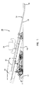
- a drilling apparatus 10 is disclosed.
- the drilling apparatus 10 includes a support 12 mounted on the ground 11 and angled to direct a drill string 14 to penetrate the ground 11.
- the drill string 14 terminates at a drill head 16 which includes a cutting member 18 (Figs. 2-4) for cutting away dirt, rock or the like.
- a drive mechanism 20 is provided for both rotating the drill string 14 and forcing the drill string 14 in a longitudinal direction.
- Figs. 2-4 show a conventional drill head 16.
- the head 16 is coupled to a terminal end of the drill string 14.
- the head 16 includes a cutting member 18 (such as cutting teeth 18) for cutting rock, dirt or the like as the drill string 14 is rotated.
- the teeth are offset from the axis X-X about which they rotate as drill string 14 rotates.
- the drill head 16 is angled at flat 17 on a side thereof 180° opposite teeth 18.
- Drill heads come in a wide variety of geometries. Examples of such are shown in U.S. Patent Nos. 5,242,026 and 5,341,887. While a particular drill head 16 is shown for purposes of illustrating the present invention, any number of different designs can be used with the present invention.
- the drill string 14 comprises a plurality of rod segments 22. After a rod segment 22 has been axially (i.e., longitudinally) advanced, the drive 20 is decoupled from the drill string 14 and is retracted so that a new rod segment 22 may be loaded onto the apparatus 10. A new rod segment 22 is threadedly connected to the drill string 14. After attachment of the new rod segment 22 to the drill string 14, the rod segment 22 is now part of the drill string 14 and the entire drill string 14 is once again both rotated and/or longitudinally advanced by the drive 20.
- the drive 20 is controlled by a controller 24 which is schematically shown in Fig. 1.
- the controller 24 controls whether the drive 20 is rotating the drill string 14, advancing the drill string 14 or whether the drive 20 is retracting to permit placement of a new rod segment 22 on the apparatus 10.
- the rod segments 22 are metal and are sufficiently rigid to transmit rotational and axial forces from the drive 20 to the drill head 16.
- the drill string 14 (although composed of rigid segments 22) is sufficiently flexible so that the string 14 can follow a curved path.
- the present invention is directed to a novel method of operation of the drilling apparatus 10. More particularly. the present invention is directed to a novel method of operation which includes intermittent retraction of the drill string 14 during the drilling operation to control a direction of movement of the drill head 16.
- the geometry of the drill head 16 and offset cutting member 18 cut through rock such that after partial rotation of the drill head 16 about its axis X-X, a portion of rock is cut away as waste and a remaining portion remains in the bore.
- This is best illustrated in Figs. 5-7 where the drill head 16 and cutting member 18 are illustrated within a bore hole 200 and where the geometry of the drill head 16 is such that in the absence of complete rotation of the drill head 16 about its axis X-X, a portion of the bore hole remains uncut and defines a ramp or cam surface 28. Recognizing the formation of ramp surface 28, Applicants have devised a novel method for controlling the drilling apparatus 10 which takes advantage of the formation of a ramp surface 28 in order to direct a drill head 16 in a desired direction angled away from a straight path.
- a path 30 defined by cutting member 18 as drill head 16 rotates about an axis X-X as the drill string 14 is rotated by the drive 20.
- the cutting member 18 follows the path of circle 30.
- a straight bore 200 having generally circular cross-section is formed.
- the drive 20 through well-known hydraulic controls, maintains the cutting head 18 forced against a terminal end 201 (Figs. 5-7) of the bore 200 (and hence, against a rock to be cut) with a predetermined force in order to attain the most efficient cutting by the cutting member 18.
- the cutting member 18 be maintained against the face of the Caliche rock at about 2500 psi for the cutting member 18 to remove rock most efficiently. Since a constant forward thrust is being applied at 2500 psi and since the cutting member 18 is removing rock constantly throughout a constant rotation, the drill string 14 is being longitudinally and axially advanced along a straight line following axis X-X.
- the present invention includes advancing the drill head 16 with the cutting force (i.e., 2500 psi in the event of Caliche rock) applied when the cutting member 18 is within a prescribed arc of rotation B (for example, between the ten o'clock position and the two o'clock position in Fig. 8).
- the arc of rotation B is bisected by the desired direction A of deflection.
- the drill string 14 When the cutting member 18 is outside of the arc B of rotation, the drill string 14 is retracted by the drive 20 such that the cutting member 18 is not cutting against the face of the rock at the terminal end 201 of the bore 200. Specifically, after completion of the cutting throughout the arc B of rotation, the drill string 14 is retracted by retracting the drive 20 such that the cutting head 18 is retracted a distance sufficient for the cutting head 18 to complete its rotation without cutting away from any of the ramp surface 28.
- the arc of rotation B is from the ten o'clock to the two o'clock position in Fig. 8. Therefore, during rotation, when the drill head 16 is in the ten o'clock position, the drill string 14 is advanced by longitudinally advancing the drive 20. The drill string is advanced such that when the cutting member 18 engages rock, it is urged against the rock face with a desired force for efficient cutting (for example, 2500 psi). The cutting member 18 remains urged against the rock face throughout the arc B until the two o'clock is attained at which point the drive 20 is retracted. Throughout the operation, the drive 20 continues to rotate the drill string 14 in a continuous rotation at any selected desired rate of rotation (for example, 70 rpm).
- a desired force for efficient cutting for example, 2500 psi
- the present method avoids compressive resistance of the rock and cuts away from the rock against its least resistive forces.
- the cutting member 18 is removing rock from the face (for example, to a depth of about two inches for each rotation). Therefore, as the cutting member 18 approaches the ten o'clock and is further advanced into the bore hole 200, the drill head 16 is longitudinally advanced about two inches beyond its position in the previous cutting along arc B. As the cutting member 18 is further advanced, a surface (conveniently referred to herein as a cam follower surface 40) under either the drill string or the drill head engages the ramp 28 (see Fig. 7). Longitudinal thrusting of the drill string 14 causes the cam follower surface 40 to engage the ramp surface 28 which deflects the drill head 16 (and hence the cutting member 18) along the desired direction of deflection A.
- a surface (conveniently referred to herein as a cam follower surface 40) under either the drill string or the drill head engages the ramp 28 (see Fig. 7). Longitudinal thrusting of the drill string 14 causes the cam follower surface 40 to engage the ramp surface 28 which deflects the drill
- Fig. 9 illustrates a common plot of the displacement of the drill head 16 during the method of the present invention.
- the horizontal axis is the rotational position of the drill head 16.
- the axial displacement is indicated (in inches) with a negative value indicating penetration into the bore hole from an arbitrarily selected start position (the zero position) and a positive value representing a retraction relative to the start position.
- the horizontal axis is numbered corresponding with positioning on a clock with twelve o'clock representing a vertical "up” and six o'clock representing vertical "down”.
- Fig. 9 presents a graph 50 showing the relative axial displacement of the drill head 16 for two rotations of the drill head 16 about the axis X-X.
- Fig. 9 pertains to the aforementioned example where the desired direction of deflection A is the twelve o'clock position and where axial thrusting commences at the ten o'clock position and retraction commences at the two o'clock position.
- the drill head 16 is fully advanced at the two o'clock position (i.e., at the end of the cutting arc B of rotation of the previous cycle). As rotation continues, the drill head 16 is retracted until it is fully retracted at point 52 which corresponds to the six o'clock position which is 180° opposite of the desired direction of deflection A (corresponding to the twelve o'clock position). At the fully retracted position 52, the drill string 14 is longitudinally advanced and the drill head 16 engages the rock face 20 at the ten o'clock position 53 at which point cutting commences. Cutting continues with continuing advancement of the drill head 16 until the next two o'clock position 54 at which point retraction commences and the cycle continues.
- the desired direction A of deflection is mid-point between the beginning cutting position 53 and the end cutting position 54. Further, since the drill head 16 is being simultaneously advanced while removing waste material, there is a net penetration D between the two o'clock position 51 at the start of the cycle and the two o'clock position 54 at the end of the cycle.
- the rotation versus the axial positioning of the drill head 16 is not a linear function. Instead, the axial advancement and retraction is an exponential function relative to the rotational position. In other words, when the drilling head 16 is retracted starting at the two o'clock position, it is retracted at a progressively increasing rate relative to the rotational velocity in order to avoid the cutting member 18 from cutting away from the ramp material 28.
- the true rotational orientation of the drill head 16 must be determined. Thereafter the rotational position of the head 16 can be calculated by controller 24. For example, the controller can presume that drill head 16 has rotated 90° after the drive 20 has rotated 90°.
- the true orientation of the drill head 16 can be initially determined (and subsequently calculated by monitoring the amount of rotation of the drill string 14 by the drive 20 to calculate a calculated rotational position), the true rotational position may subsequently become out of alignment with the calculated rotational position.
- the actual rotational position of the drill head 16 may be out of alignment with the calculated rotational position due to tolerances and other inaccuracies resulting from threadedly attaching rod segments 22 to the drill string 14. Therefore, it is preferred that the actual position of the drill head 16 be calculated after a rod segment 22 is threadedly attached to the drill string 14.
- the actual angular position of the drill head 16 can be calculated in many ways known in the art.
- the drill head 16 may contain a transmitter or the like (not shown) transmitting its rotational position which can be radio transmitted to a receiver (not shown) above ground as is common in the art.
- the operator can rotate drill string 14 until the drill head is in a start position (e.g., the twelve o'clock position).
- a reset button or the like can be pressed on the controller 24 to reset the starting angular position at the twelve o'clock position.
- the amount of rotational movement of the drive 20 may be used to calculate the angular position of the drill head 16 until a new rod segment 22 is attached.
- the rotational position of the drill head 16 could be determined in any one of a number of different ways.
- the actual rotational position of the drill head 16 could be constantly monitored and relayed to controller 24 through a variety of means including hard wire connection from the drill head 16 to the controller 24 or radio or other transmission from the drill head 16 to the controller 24.
- the need to periodically reset the angular position of the drill head on the controller 24 and to subsequently calculate the position of the drill head 24 by means of calculating the amount of rotation of the drive 20 could be avoided.
- Fig. 10 is a flow chart illustrating the steps of controller 24 for controlling the operation of the apparatus 10. After a period of boring in a straight line, it may be desired to deflect the direction of the boring. Therefore, the controller 24 controls directional boring at a start 100 of the directional boring process.
- an operator may manually input to the controller 24 a variety of operating parameters. For example, the operator will input a desired angular direction of deflection. In the example previously given, the operator would input a twelve o'clock position to indicate to the controller 24 that is desired to deflect the drill head 16 vertically. Further, the operator will input the size of the arc for cutting. For example, the arc B in Fig. 8 is illustrated as being 120° from a ten o'clock position to a two o'clock position. Preferably, the controller 24 will permit selection of an arc between 0° to 180°.
- An additional operating parameter to be set by an operator is a desired thrust for longitudinal advancement of the drill head 16.
- a desired thrust for example, for Caliche rock, a desired thrust of 2500 psi may be set.
- the operator also sets a desired rotational speed for the drill string 14 (for example, a rotational speed between 0 to 120 rpm).
- the operator additionally resets the starting or twelve o'clock position for the drill head 16. As previously indicated, the reset is done by detecting through remote transmissions or otherwise when the drill head is rotated with the cutting member 18 generally vertically aligned in a twelve o'clock position. The operator may then set a reset button indicating to the controller that the drill head is, in fact, in the twelve o'clock position. Afterwards, rotational increments of the drive 20 are monitored to calculate the rotational position of the drill head 16. The reset of the twelve o'clock position is reestablished each time a new drill segment 22 is added.
- the operating parameters inputted at step 101 further include the establishment of a pullback distance.
- the pullback distance could be from 2 to 6 inches depending on the geometry of the drilling head 16 so that during the pullback, the drill head 16 is not cutting into the desired ramp 28 as the drill head 16 is rotating outside of the arc B of rotation.
- the controller 24 can determine the starting point for the cutting operation. For example, where the desired deflection direction is known to be the twelve o'clock position and where the arc B is set at 120° by the operator, the controller establishes the starting point at the ten o'clock such that the desired direction of deflection (i.e., vertical in the aforementioned example) bisects the arc (120°) inputted by the operator at step 101. Accordingly, for the examples given, the controller 24 sets the ten o'clock position as the starting point.
- the controller 24 determines if the drill head 16 is rotating at the desired rotational velocity. If not, power is increased at step 103 to rotate the drill head 16.
- the controller 24 determines if the drill head 16 has achieved the starting point (i.e., the ten o'clock position in the foregoing example) at step 104. If not, rotation is continued until the ten o'clock position is achieved.
- the controller 24 determines, at step 105, if the pressure on the rock face is the preset thrust pressure. If not, the thrust pressure is increased at step 106 until the desired preset thrust pressure is achieved.
- the controller 24 determines if the two o'clock position (the end of the cutting arc B in the aforementioned example) has been achieved. If not. rotation continues until the end of the cutting arc is achieved.
- the thrust is reversed at step 108 in order to retract the drill head 16.
- the rotational velocity of the drill string 14 and the reversed longitudinal speed of the drill string 14 are compared at step 109 to match the relations of Fig. 10. If the thrust rate and the rotation are not in correct proportion. the thrust is varied at step 110. If the complete amount of directional deviation is not achieved as indicated at step 111, the process is continued. Otherwise, straight line boring with simultaneous rotation and forward longitudinal thrusting without retraction are commenced.
- a drill head 16 is shown fully inserted into a bore 200 with the drill teeth 18 and the drill head 16 at the twelve o'clock position.
- the drill head 16 is fully retracted as shown in Fig. 6, where the drill teeth and drill head are in the six o'clock position. Due to the retraction, the teeth 18 do not drill into and remove waste from the ramp 28.
- the cam follower 40 engages the ramp 28 forcing the drill head 16 to deflect upwardly in the direction A (Fig. 7).
Landscapes
- Engineering & Computer Science (AREA)
- Geology (AREA)
- Mining & Mineral Resources (AREA)
- Life Sciences & Earth Sciences (AREA)
- General Life Sciences & Earth Sciences (AREA)
- Fluid Mechanics (AREA)
- Environmental & Geological Engineering (AREA)
- Physics & Mathematics (AREA)
- Geochemistry & Mineralogy (AREA)
- Mechanical Engineering (AREA)
- Earth Drilling (AREA)
- Drilling And Boring (AREA)
- Drilling And Exploitation, And Mining Machines And Methods (AREA)
- Soil Working Implements (AREA)
- Acyclic And Carbocyclic Compounds In Medicinal Compositions (AREA)
Claims (24)
- Procédé pour commander un dispositif de forage (10) destiné à creuser un trou de forage dans un milieu (11), ledit dispositif ayant un train de tiges de forage (14) se finissant au niveau d'une tête de forage (16) qui tourne sur un axe de rotation (X-X), ladite tête de forage comprenant un élément de coupe (18) sélectionné pour creuser en un point décalé par rapport audit axe (X-X), ledit dispositif comprenant des moyens (20) pour faire avancer ladite tête de forage (16) longitudinalement, ledit procédé comprenant :
le fait de faire avancer ladite tête de forage (16) dans une direction souhaitée suivant un angle s'écartant d'une trajectoire rectiligne en :a. appliquant une force longitudinale à ladite tête de forage (16) lorsque ledit élément de coupe (18) se trouve dans un arc de rotation que ladite direction souhaitée traverse ; ledit procédé étant caractérisé en outre parb. le fait de relâcher ladite force longitudinale et de retirer la tête de forage (16) lorsque ledit élément de coupe (18) se trouve en dehors dudit arc de rotation de sorte qu'une rampe de milieu non creusé se forme en une face du forage qui est généralement opposée à la direction souhaitée ; etc. le fait d'appliquer de nouveau une force longitudinale au niveau de la tête de forage (16) et de faire avancer la tête de forage (16) longitudinalement lorsque l'élément de coupe (18) se trouve à nouveau dans l'arc de rotation, dans lequel la rampe de milieu non creusé provoque la déviation de la tête de forage (16) dans la direction souhaitée alors que l'avancement de la tête de forage (16) s'effectue longitudinalement. - Procédé selon la revendication 1, comprenant le fait de sélectionner ledit arc de rotation pour que ladite direction souhaitée bissecte ledit arc de rotation.
- Procédé selon la revendication 1, dans lequel ledit arc de rotation est compris entre 0 degré et 180 degrés.
- Procédé selon la revendication 3, dans lequel ledit arc de rotation est de 120 degrés.
- Procédé selon la revendication 2, dans lequel ledit arc de rotation est compris entre 0 degré et 180 degrés.
- Procédé selon la revendication 5, dans lequel ledit arc de rotation est de 120 degrés.
- Procédé selon la revendication 1, dans lequel ladite force longitudinale est sélectionnée pour que ledit élément de coupe (18) soit appliqué contre ledit milieu à forer, parmi une gamme de valeurs de pression spécifiée pour que ledit élément de coupe (18) enlève des déblais dudit milieu (11) au fond dudit trou de forage.
- Procédé selon la revendication 1, dans lequel ledit retrait comprend le fait de retirer ledit élément de coupe (18) en l'écartant d'une face dudit milieu au niveau dudit fond dudit trou de forage d'une grandeur sélectionnée pour ledit élément de coupe (18) pour éviter un creusement important dudit milieu quand ledit élément de coupe (18) se trouve en dehors dudit arc de rotation.
- Procédé selon la revendication 1, dans lequel ledit train de tiges de forage (14) comprend une extrémité extérieure (22) exposée en dehors dudit trou de forage et montée sur un système d'entraínement (20) servant à faire avancer ledit train de tiges de forage (14) longitudinalement et à le faire tourner, ladite application de ladite force comprenant le fait de faire avancer ladite extrémité extérieure (22) au moyen dudit système d'entraínement (20).
- Procédé selon la revendication 9, dans lequel ledit fait de faire tourner ledit train de tiges comprend la rotation de ladite extrémité extérieure (22) au moyen dudit système d'entraínement (20).
- Procédé selon la revendication 9, dans lequel ledit fait de retirer comprend le retrait de ladite extrémité extérieure (22) au moyen dudit système d'entraínement (20).
- Procédé selon la revendication 1, dans lequel une position rotatoire de ladite tête de forage (16) est déterminée en contrôlant une grandeur de rotation de ladite extrémité extérieure (22) au moyen dudit système d'entraínement (20).
- Procédé selon la revendication 9, dans lequel une position rotatoire desdites têtes de forage (16) est déterminée en contrôlant une grandeur de rotation de ladite extrémité extérieure (22) au moyen dudit système d'entraínement (20).
- Procédé selon la revendication 1, dans lequel une position rotatoire de ladite tête de forage (16) est déterminée par des signaux de contrôle de ladite tête de forage (16) qui en indiquent ladite position rotatoire.
- Procédé selon la revendication 9, dans lequel ledit train de tiges de forage (14) comporte une pluralité de segments de tiges de forage (22) réunis séquentiellement au niveau dudit système d'entraínement (20) situé en dehors dudit trou de forage, ledit procédé comprenant le fait de mesurer une position rotatoire effective de ladite tête de forage (16) suite à l'ajout d'un segment (22) audit train de tiges de forage (14), puis le fait de déterminer une position rotatoire de ladite tête de forage (16) en contrôlant une grandeur de rotation ultérieure de ladite extrémité extérieure au moyen dudit système d'entraínement (20).
- Procédé selon la revendication 1, comprenant en outre le fait de réaliser plusieurs fois les étapes (a), (b) et (c) pour que ladite tête de forage (16) soit déviée dans ladite direction souhaitée pendant ledit avancement par opposition aux surfaces dudit milieu (11) définissant ledit trou de forage.
- Procédé selon la revendication 1, comprenant le fait de faire avancer ladite tête de forage (16) le long de ladite trajectoire rectiligne tout en faisant tourner simultanément ladite tête de forage (16) et en appliquant une force longitudinale à ladite tête de forage (16).
- Dispositif de forage pour creuser un trou de forage dans un milieu (11), ledit dispositif comprenant :un train de tiges de forage (14) se terminant au niveau d'une tête de forage (16) à l'intérieur dudit trou de forage ;un système d'entraínement (20) situé en dehors dudit trou de forage pour pouvoir y engager une extrémité extérieure (22) dudit train de tiges de forage (14), ledit système d'entraínement ayant un premier moteur de commande pour faire tourner ledit train de tiges de forage (14) sur un axe de rotation (X-X) coïncidant avec un axe longitudinal (X-X) dudit train de tiges de forage (14) et un deuxième moteur de commande pour faire avancer ladite tête de forage (16) longitudinalement et pour la retirer ;ladite tête de forage (16) comprenant un élément de coupe (18) sélectionné pour creuser en un point décalé par rapport audit axe (X-X) ;un appareil de contrôle (24) pour faire avancer ladite tête de forage (16) dans une direction souhaitée suivant un angle s'écartant d'une trajectoire rectiligne en :a. faisant marcher lesdits premier et deuxième moteurs de commande pour appliquer une force longitudinale à ladite tête de forage (16) lorsque ledit élément de coupe (18) se trouve dans un arc de rotation que ladite direction souhaitée traverse ;
et caractérisé en ce que ledit appareil de contrôle (24) est proposé pour faire avancer ladite tête de forage (16) dans ladite direction souhaitée, et caractérisé en outre parb. le fait de contrôler ledit deuxième moteur de commande pour retirer ladite tête de forage (16) lorsque ledit élément de coupe (18) se trouve en dehors dudit arc de rotation ; et parc. le fait de contrôler ledit deuxième moteur de commande pour appliquer de nouveau une force longitudinale au niveau de la tête de forage (16) et pour faire avancer la tête de forage (16) longitudinalement lorsque l'élément de coupe (18) se trouve à nouveau dans l'arc de rotation. - Dispositif de forage selon la revendication 18, dans lequel ledit élément de coupe (18) est sélectionné pour détacher des déblais dudit milieu (11) au niveau dudit fond dudit trou de forage avec une portion restante dudit milieu présentant une surface destinée à une came en une face dudit trou de forage opposée à ladite direction souhaitée.
- Dispositif de forage selon la revendication 19, dans lequel ledit train de tiges de forage (14) comprend un galet de came (17) positionné sur un de ses côtés pour agir contre ladite surface destinée à la came afin de faire dévier ladite tête de forage (16) dans ladite direction souhaitée alors que l'avancement de ladite tête de forage (16) s'effectue longitudinalement.
- Dispositif de forage selon la revendication 18, dans lequel le premier moteur de commande fait tourner en permanence le train de tiges de forage (14) alors que le train de tiges de forage (14) est retiré et avancé par le deuxième moteur de commande.
- Procédé selon la revendication 1, comprenant la rotation ininterrompue de ladite tête de forage (16) pendant ledit retrait.
- Procédé selon la revendication 1, dans lequel ladite tête de forage (16) est tournée en permanence alors que la tête de forage (16) est retirée et avancée.
- Procédé selon la revendication 23, dans lequel la tête de forage (16) est tournée à vitesse constante.
Applications Claiming Priority (3)
| Application Number | Priority Date | Filing Date | Title |
|---|---|---|---|
| US61854196A | 1996-03-04 | 1996-03-04 | |
| US618541 | 1996-03-04 | ||
| PCT/US1996/012930 WO1997033065A1 (fr) | 1996-03-04 | 1996-08-06 | Forage directionnel |
Publications (2)
| Publication Number | Publication Date |
|---|---|
| EP0885343A1 EP0885343A1 (fr) | 1998-12-23 |
| EP0885343B1 true EP0885343B1 (fr) | 2001-02-21 |
Family
ID=24478141
Family Applications (1)
| Application Number | Title | Priority Date | Filing Date |
|---|---|---|---|
| EP96928827A Expired - Lifetime EP0885343B1 (fr) | 1996-03-04 | 1996-08-06 | Forage directionnel |
Country Status (11)
| Country | Link |
|---|---|
| US (1) | US5778991A (fr) |
| EP (1) | EP0885343B1 (fr) |
| JP (1) | JP2000505165A (fr) |
| CN (1) | CN1080361C (fr) |
| AT (1) | ATE199273T1 (fr) |
| AU (1) | AU6844096A (fr) |
| BR (1) | BR9612567A (fr) |
| CA (1) | CA2248024A1 (fr) |
| DE (1) | DE69611846T2 (fr) |
| RU (1) | RU2163963C2 (fr) |
| WO (1) | WO1997033065A1 (fr) |
Families Citing this family (46)
| Publication number | Priority date | Publication date | Assignee | Title |
|---|---|---|---|---|
| US5899283A (en) * | 1997-02-05 | 1999-05-04 | Railhead Underground Products, L.L.C. | Drill bit for horizontal directional drilling of rock formations |
| US5934391A (en) * | 1997-02-05 | 1999-08-10 | Railhead Underground Products, L.L.C. | Sonde housing door hold-down system |
| US6247544B1 (en) | 1997-03-06 | 2001-06-19 | Vermeer Manufacturing Company | Duckbill with cutting teeth |
| US6109371A (en) * | 1997-03-23 | 2000-08-29 | The Charles Machine Works, Inc. | Method and apparatus for steering an earth boring tool |
| US6179068B1 (en) * | 1997-05-08 | 2001-01-30 | Flexidrill Limited | Directional drilling apparatus |
| US6148935A (en) * | 1998-08-24 | 2000-11-21 | Earth Tool Company, L.L.C. | Joint for use in a directional boring apparatus |
| US6371223B2 (en) | 1999-03-03 | 2002-04-16 | Earth Tool Company, L.L.C. | Drill head for directional boring |
| CA2366115A1 (fr) | 1999-03-03 | 2000-09-21 | Earth Tool Company, L.L.C. | Procede et appareil de forage dirige |
| EP1083292A1 (fr) | 1999-09-10 | 2001-03-14 | Earth Tool Company L.L.C. | Système de trépan interchangeable pour forage directionnel |
| US6302410B1 (en) | 1999-10-22 | 2001-10-16 | Earth Tool Company, L.L.C. | Rod gripping jaw |
| US6308789B1 (en) * | 1999-10-26 | 2001-10-30 | Neal A. Kuenzi | Drill bit for directional drilling |
| US6422782B1 (en) | 1999-12-16 | 2002-07-23 | Earth Tool Company, L.L.C. | Apparatus for mounting an electronic device for use in directional drilling |
| US6527063B2 (en) | 2000-02-17 | 2003-03-04 | Wendall D. Rust | Directional boring device |
| AU2001241969A1 (en) | 2000-03-03 | 2001-09-17 | Vermeer Manufacturing Company | Method and apparatus for directional boring under mixed conditions |
| US6357537B1 (en) | 2000-03-15 | 2002-03-19 | Vermeer Manufacturing Company | Directional drilling machine and method of directional drilling |
| US6491115B2 (en) * | 2000-03-15 | 2002-12-10 | Vermeer Manufacturing Company | Directional drilling machine and method of directional drilling |
| US6450269B1 (en) | 2000-09-07 | 2002-09-17 | Earth Tool Company, L.L.C. | Method and bit for directional horizontal boring |
| DE10101708B4 (de) * | 2001-01-15 | 2006-02-09 | Tracto-Technik Gmbh | Verfahren zum Felsmeißeln |
| US6789635B2 (en) | 2001-06-18 | 2004-09-14 | Earth Tool Company, L.L.C. | Drill bit for directional drilling in cobble formations |
| WO2003027714A1 (fr) * | 2001-09-25 | 2003-04-03 | Vermeer Manufacturing Company | Architecture d'interface communie pour machines de forage horizontal et systemes de guidage de surface |
| US7086808B2 (en) * | 2001-12-20 | 2006-08-08 | Earth Tool Company, L.L.C. | Method and apparatus for on-grade boring |
| US7549489B2 (en) | 2006-03-23 | 2009-06-23 | Hall David R | Jack element with a stop-off |
| US7753144B2 (en) | 2005-11-21 | 2010-07-13 | Schlumberger Technology Corporation | Drill bit with a retained jack element |
| US7641003B2 (en) | 2005-11-21 | 2010-01-05 | David R Hall | Downhole hammer assembly |
| US7360610B2 (en) * | 2005-11-21 | 2008-04-22 | Hall David R | Drill bit assembly for directional drilling |
| US8297375B2 (en) | 2005-11-21 | 2012-10-30 | Schlumberger Technology Corporation | Downhole turbine |
| US8316964B2 (en) | 2006-03-23 | 2012-11-27 | Schlumberger Technology Corporation | Drill bit transducer device |
| US8225883B2 (en) | 2005-11-21 | 2012-07-24 | Schlumberger Technology Corporation | Downhole percussive tool with alternating pressure differentials |
| US7571780B2 (en) | 2006-03-24 | 2009-08-11 | Hall David R | Jack element for a drill bit |
| US8267196B2 (en) | 2005-11-21 | 2012-09-18 | Schlumberger Technology Corporation | Flow guide actuation |
| US8297378B2 (en) | 2005-11-21 | 2012-10-30 | Schlumberger Technology Corporation | Turbine driven hammer that oscillates at a constant frequency |
| US8360174B2 (en) | 2006-03-23 | 2013-01-29 | Schlumberger Technology Corporation | Lead the bit rotary steerable tool |
| US8528664B2 (en) | 2005-11-21 | 2013-09-10 | Schlumberger Technology Corporation | Downhole mechanism |
| US8522897B2 (en) | 2005-11-21 | 2013-09-03 | Schlumberger Technology Corporation | Lead the bit rotary steerable tool |
| US7954401B2 (en) | 2006-10-27 | 2011-06-07 | Schlumberger Technology Corporation | Method of assembling a drill bit with a jack element |
| RU2330928C1 (ru) * | 2007-01-17 | 2008-08-10 | Дмитрий Анатольевич Ермолин | Гидромониторная бурильная головка |
| US7866416B2 (en) | 2007-06-04 | 2011-01-11 | Schlumberger Technology Corporation | Clutch for a jack element |
| US7967083B2 (en) * | 2007-09-06 | 2011-06-28 | Schlumberger Technology Corporation | Sensor for determining a position of a jack element |
| US7721826B2 (en) | 2007-09-06 | 2010-05-25 | Schlumberger Technology Corporation | Downhole jack assembly sensor |
| US8701799B2 (en) | 2009-04-29 | 2014-04-22 | Schlumberger Technology Corporation | Drill bit cutter pocket restitution |
| US8196677B2 (en) | 2009-08-04 | 2012-06-12 | Pioneer One, Inc. | Horizontal drilling system |
| US10024105B2 (en) | 2015-02-25 | 2018-07-17 | Radius Hdd Direct, Llc | Rock bit |
| JP7032152B2 (ja) * | 2018-01-26 | 2022-03-08 | ケミカルグラウト株式会社 | 削孔用ビット |
| ZA201906123B (en) * | 2019-09-17 | 2021-06-30 | Nicolas Jacobus Bischoff | Drill assembly and method of using same |
| CN114624126B (zh) * | 2022-05-11 | 2022-07-29 | 四川中铁二院环保科技有限公司 | 一种岩土原位剪切测试设备及方法 |
| CN117072064B (zh) * | 2023-08-28 | 2025-11-18 | 山东大学 | 一种用于深孔钻机的射流智能纠偏控制系统及方法 |
Family Cites Families (37)
| Publication number | Priority date | Publication date | Assignee | Title |
|---|---|---|---|---|
| US2300016A (en) * | 1939-04-03 | 1942-10-27 | Reed Roller Bit Co | Directional drilling apparatus |
| US2324102A (en) * | 1940-02-09 | 1943-07-13 | Eastman Oil Well Survey Co | Means for directional drilling |
| US2783972A (en) * | 1954-02-24 | 1957-03-05 | Fur Grundwasserbauten Ag | Installation for making bores in a stratum |
| US3525405A (en) * | 1968-06-17 | 1970-08-25 | Bell Telephone Labor Inc | Guided burrowing device |
| US3529682A (en) * | 1968-10-03 | 1970-09-22 | Bell Telephone Labor Inc | Location detection and guidance systems for burrowing device |
| US3536151A (en) * | 1968-10-21 | 1970-10-27 | Brite Lite Enterprises Inc | Earth boring tool |
| US3878903A (en) * | 1973-12-04 | 1975-04-22 | Martin Dee Cherrington | Apparatus and process for drilling underground arcuate paths |
| JPS603496B2 (ja) * | 1977-03-17 | 1985-01-29 | ユニチカ株式会社 | 医療用カテーテル |
| US4144941A (en) * | 1977-09-30 | 1979-03-20 | Ritter Lester L | Directional impact tool for tunneling |
| US4262758A (en) * | 1978-07-27 | 1981-04-21 | Evans Robert F | Borehole angle control by gage corner removal from mechanical devices associated with drill bit and drill string |
| US4453603A (en) * | 1980-12-09 | 1984-06-12 | Voss Development Corporation | Apparatus and method for selected path drilling |
| US4396073A (en) * | 1981-09-18 | 1983-08-02 | Electric Power Research Institute, Inc. | Underground boring apparatus with controlled steering capabilities |
| US4416339A (en) * | 1982-01-21 | 1983-11-22 | Baker Royce E | Bit guidance device and method |
| US4674579A (en) * | 1985-03-07 | 1987-06-23 | Flowmole Corporation | Method and apparatus for installment of underground utilities |
| US4787463A (en) * | 1985-03-07 | 1988-11-29 | Flowmole Corporation | Method and apparatus for installment of underground utilities |
| US4632191A (en) * | 1985-04-05 | 1986-12-30 | Gas Research Institute | Steering system for percussion boring tools |
| DE3680402D1 (de) * | 1985-05-14 | 1991-08-29 | Cherrington Corp | Vorrichtung und verfahren zum herstellen eines vergroesserten gekruemmten bohrlochs im untergrund und zum installieren eines rohres darin. |
| USRE33793E (en) * | 1985-05-14 | 1992-01-14 | Cherrington Corporation | Apparatus and method for forming an enlarged underground arcuate bore and installing a conduit therein |
| US4679637A (en) * | 1985-05-14 | 1987-07-14 | Cherrington Martin D | Apparatus and method for forming an enlarged underground arcuate bore and installing a conduit therein |
| US4637479A (en) * | 1985-05-31 | 1987-01-20 | Schlumberger Technology Corporation | Methods and apparatus for controlled directional drilling of boreholes |
| US4694913A (en) * | 1986-05-16 | 1987-09-22 | Gas Research Institute | Guided earth boring tool |
| US4856600A (en) * | 1986-05-22 | 1989-08-15 | Flowmole Corporation | Technique for providing an underground tunnel utilizing a powered boring device |
| US4714118A (en) * | 1986-05-22 | 1987-12-22 | Flowmole Corporation | Technique for steering and monitoring the orientation of a powered underground boring device |
| US4823888A (en) * | 1986-12-30 | 1989-04-25 | Smet Nic H W | Apparatus for making a subterranean tunnel |
| SU1740603A1 (ru) * | 1988-04-27 | 1992-06-15 | Московский геологоразведочный институт им.С.Орджоникидзе | Способ направленного бурени скважин |
| SU1698411A1 (ru) * | 1988-04-27 | 1991-12-15 | Московский Геологоразведочный Институт Им.Серго Орджоникидзе | Способ направленного бурени скважин |
| US4867255A (en) * | 1988-05-20 | 1989-09-19 | Flowmole Corporation | Technique for steering a downhole hammer |
| US4953638A (en) * | 1988-06-27 | 1990-09-04 | The Charles Machine Works, Inc. | Method of and apparatus for drilling a horizontal controlled borehole in the earth |
| US5148880A (en) * | 1990-08-31 | 1992-09-22 | The Charles Machine Works, Inc. | Apparatus for drilling a horizontal controlled borehole in the earth |
| SE464145B (sv) * | 1988-08-31 | 1991-03-11 | Diamant Boart Craelius Ab | Anordning foer upptagning av haal i marken |
| US4991667A (en) * | 1989-11-17 | 1991-02-12 | Ben Wade Oakes Dickinson, III | Hydraulic drilling apparatus and method |
| EP0467642A3 (en) * | 1990-07-17 | 1993-03-10 | Camco Drilling Group Limited | Earth drilling system and method for controlling the direction of a borehole |
| DE4103196C2 (de) * | 1991-02-02 | 1994-06-09 | Tracto Technik | Bohrgerät |
| US5553678A (en) * | 1991-08-30 | 1996-09-10 | Camco International Inc. | Modulated bias units for steerable rotary drilling systems |
| US5449046A (en) * | 1993-12-23 | 1995-09-12 | Electric Power Research Institute, Inc. | Earth boring tool with continuous rotation impulsed steering |
| US5513713A (en) * | 1994-01-25 | 1996-05-07 | The United States Of America As Represented By The Secretary Of The Navy | Steerable drillhead |
| US5421420A (en) * | 1994-06-07 | 1995-06-06 | Schlumberger Technology Corporation | Downhole weight-on-bit control for directional drilling |
-
1996
- 1996-08-06 RU RU98118099/03A patent/RU2163963C2/ru active
- 1996-08-06 AU AU68440/96A patent/AU6844096A/en not_active Abandoned
- 1996-08-06 JP JP9512992A patent/JP2000505165A/ja active Pending
- 1996-08-06 DE DE69611846T patent/DE69611846T2/de not_active Expired - Lifetime
- 1996-08-06 CA CA002248024A patent/CA2248024A1/fr not_active Abandoned
- 1996-08-06 CN CN96180173A patent/CN1080361C/zh not_active Expired - Fee Related
- 1996-08-06 AT AT96928827T patent/ATE199273T1/de not_active IP Right Cessation
- 1996-08-06 EP EP96928827A patent/EP0885343B1/fr not_active Expired - Lifetime
- 1996-08-06 BR BR9612567A patent/BR9612567A/pt not_active Application Discontinuation
- 1996-08-06 WO PCT/US1996/012930 patent/WO1997033065A1/fr not_active Ceased
- 1996-08-29 US US08/705,007 patent/US5778991A/en not_active Expired - Lifetime
Also Published As
| Publication number | Publication date |
|---|---|
| CN1214101A (zh) | 1999-04-14 |
| DE69611846D1 (de) | 2001-03-29 |
| CN1080361C (zh) | 2002-03-06 |
| WO1997033065A1 (fr) | 1997-09-12 |
| US5778991A (en) | 1998-07-14 |
| JP2000505165A (ja) | 2000-04-25 |
| BR9612567A (pt) | 1999-07-20 |
| DE69611846T2 (de) | 2001-10-04 |
| CA2248024A1 (fr) | 1997-09-12 |
| RU2163963C2 (ru) | 2001-03-10 |
| EP0885343A1 (fr) | 1998-12-23 |
| ATE199273T1 (de) | 2001-03-15 |
| AU6844096A (en) | 1997-09-22 |
Similar Documents
| Publication | Publication Date | Title |
|---|---|---|
| US5778991A (en) | Directional boring | |
| EP0391669B1 (fr) | Mortaiseuse de barre directionnelle | |
| JPH0220789A (ja) | ダウンホールハンマーを操縦する方法および装置 | |
| USRE44427E1 (en) | Apparatus for directional boring under mixed conditions | |
| US5449046A (en) | Earth boring tool with continuous rotation impulsed steering | |
| DE19607365C2 (de) | Verfahren zum Lenken eines Erdbohrgeräts und ein lenkbares Gerät zum Herstellen einer Erdbohrung | |
| US9976275B2 (en) | Method and apparatus for driving screwable foundations into the ground | |
| CA2142123A1 (fr) | Foreuse horizontale guidee | |
| RU98118099A (ru) | Способ управления бурильной установкой и бурильная установка | |
| US5070948A (en) | Directional rod pusher | |
| US6761231B1 (en) | Rotary driven drilling hammer | |
| CN101363307B (zh) | 在多种混合条件下进行定向钻孔的方法和装置 | |
| US20220389767A1 (en) | Systems and methods for drilling while driving foundation components | |
| US20050161261A1 (en) | Steerable soil penetration system | |
| EP0251165B1 (fr) | Moyens de forage servant comme ancrage de sol et méthode | |
| US20250223772A1 (en) | Screw anchor with consumable tip | |
| AU731418B2 (en) | Attachment member and a method of anchoring same | |
| CN114658379A (zh) | 定向取芯钻具及其使用方法 | |
| US6516902B1 (en) | Directional drilling system | |
| RU2084590C1 (ru) | Способ проходки криволинейной скважины и устройство для его осуществления | |
| RU2122074C1 (ru) | Способ корректируемой по направлению проходки скважины | |
| JP2004009703A (ja) | 連続直状孔の穿孔方法 | |
| JPH0768836B2 (ja) | 削孔装置 | |
| JP4116730B2 (ja) | トンネルの長尺先受工法 | |
| JP3790566B2 (ja) | ガイドボーリング工法に用いられる掘削装置 |
Legal Events
| Date | Code | Title | Description |
|---|---|---|---|
| PUAI | Public reference made under article 153(3) epc to a published international application that has entered the european phase |
Free format text: ORIGINAL CODE: 0009012 |
|
| 17P | Request for examination filed |
Effective date: 19980710 |
|
| AK | Designated contracting states |
Kind code of ref document: A1 Designated state(s): AT BE CH DE DK ES FI FR GB GR IE IT LI LU MC NL PT SE |
|
| 17Q | First examination report despatched |
Effective date: 19990519 |
|
| GRAG | Despatch of communication of intention to grant |
Free format text: ORIGINAL CODE: EPIDOS AGRA |
|
| GRAG | Despatch of communication of intention to grant |
Free format text: ORIGINAL CODE: EPIDOS AGRA |
|
| GRAH | Despatch of communication of intention to grant a patent |
Free format text: ORIGINAL CODE: EPIDOS IGRA |
|
| GRAH | Despatch of communication of intention to grant a patent |
Free format text: ORIGINAL CODE: EPIDOS IGRA |
|
| GRAA | (expected) grant |
Free format text: ORIGINAL CODE: 0009210 |
|
| AK | Designated contracting states |
Kind code of ref document: B1 Designated state(s): AT BE CH DE DK ES FI FR GB GR IE IT LI LU MC NL PT SE |
|
| PG25 | Lapsed in a contracting state [announced via postgrant information from national office to epo] |
Ref country code: SE Free format text: THE PATENT HAS BEEN ANNULLED BY A DECISION OF A NATIONAL AUTHORITY Effective date: 20010221 Ref country code: NL Free format text: LAPSE BECAUSE OF FAILURE TO SUBMIT A TRANSLATION OF THE DESCRIPTION OR TO PAY THE FEE WITHIN THE PRESCRIBED TIME-LIMIT Effective date: 20010221 Ref country code: LI Free format text: LAPSE BECAUSE OF FAILURE TO SUBMIT A TRANSLATION OF THE DESCRIPTION OR TO PAY THE FEE WITHIN THE PRESCRIBED TIME-LIMIT Effective date: 20010221 Ref country code: FI Free format text: LAPSE BECAUSE OF FAILURE TO SUBMIT A TRANSLATION OF THE DESCRIPTION OR TO PAY THE FEE WITHIN THE PRESCRIBED TIME-LIMIT Effective date: 20010221 Ref country code: ES Free format text: THE PATENT HAS BEEN ANNULLED BY A DECISION OF A NATIONAL AUTHORITY Effective date: 20010221 Ref country code: CH Free format text: LAPSE BECAUSE OF FAILURE TO SUBMIT A TRANSLATION OF THE DESCRIPTION OR TO PAY THE FEE WITHIN THE PRESCRIBED TIME-LIMIT Effective date: 20010221 Ref country code: BE Free format text: LAPSE BECAUSE OF FAILURE TO SUBMIT A TRANSLATION OF THE DESCRIPTION OR TO PAY THE FEE WITHIN THE PRESCRIBED TIME-LIMIT Effective date: 20010221 Ref country code: AT Free format text: LAPSE BECAUSE OF FAILURE TO SUBMIT A TRANSLATION OF THE DESCRIPTION OR TO PAY THE FEE WITHIN THE PRESCRIBED TIME-LIMIT Effective date: 20010221 |
|
| REF | Corresponds to: |
Ref document number: 199273 Country of ref document: AT Date of ref document: 20010315 Kind code of ref document: T |
|
| REG | Reference to a national code |
Ref country code: CH Ref legal event code: EP |
|
| REG | Reference to a national code |
Ref country code: IE Ref legal event code: FG4D |
|
| REF | Corresponds to: |
Ref document number: 69611846 Country of ref document: DE Date of ref document: 20010329 |
|
| ITF | It: translation for a ep patent filed | ||
| PG25 | Lapsed in a contracting state [announced via postgrant information from national office to epo] |
Ref country code: PT Free format text: LAPSE BECAUSE OF FAILURE TO SUBMIT A TRANSLATION OF THE DESCRIPTION OR TO PAY THE FEE WITHIN THE PRESCRIBED TIME-LIMIT Effective date: 20010521 Ref country code: DK Free format text: LAPSE BECAUSE OF FAILURE TO SUBMIT A TRANSLATION OF THE DESCRIPTION OR TO PAY THE FEE WITHIN THE PRESCRIBED TIME-LIMIT Effective date: 20010521 |
|
| PG25 | Lapsed in a contracting state [announced via postgrant information from national office to epo] |
Ref country code: GR Free format text: LAPSE BECAUSE OF FAILURE TO SUBMIT A TRANSLATION OF THE DESCRIPTION OR TO PAY THE FEE WITHIN THE PRESCRIBED TIME-LIMIT Effective date: 20010525 |
|
| ET | Fr: translation filed | ||
| PGFP | Annual fee paid to national office [announced via postgrant information from national office to epo] |
Ref country code: GB Payment date: 20010629 Year of fee payment: 6 |
|
| NLV1 | Nl: lapsed or annulled due to failure to fulfill the requirements of art. 29p and 29m of the patents act | ||
| PGFP | Annual fee paid to national office [announced via postgrant information from national office to epo] |
Ref country code: FR Payment date: 20010802 Year of fee payment: 6 |
|
| PG25 | Lapsed in a contracting state [announced via postgrant information from national office to epo] |
Ref country code: LU Free format text: LAPSE BECAUSE OF NON-PAYMENT OF DUE FEES Effective date: 20010806 Ref country code: IE Free format text: LAPSE BECAUSE OF NON-PAYMENT OF DUE FEES Effective date: 20010806 |
|
| REG | Reference to a national code |
Ref country code: CH Ref legal event code: PL |
|
| PLBQ | Unpublished change to opponent data |
Free format text: ORIGINAL CODE: EPIDOS OPPO |
|
| PLBI | Opposition filed |
Free format text: ORIGINAL CODE: 0009260 |
|
| REG | Reference to a national code |
Ref country code: GB Ref legal event code: IF02 |
|
| 26 | Opposition filed |
Opponent name: TRACTO-TECHNIK - PAUL SCHMIDT - SPEZIALMASCHINEN Effective date: 20011120 |
|
| PLBF | Reply of patent proprietor to notice(s) of opposition |
Free format text: ORIGINAL CODE: EPIDOS OBSO |
|
| PG25 | Lapsed in a contracting state [announced via postgrant information from national office to epo] |
Ref country code: MC Free format text: LAPSE BECAUSE OF NON-PAYMENT OF DUE FEES Effective date: 20020301 |
|
| PLBF | Reply of patent proprietor to notice(s) of opposition |
Free format text: ORIGINAL CODE: EPIDOS OBSO |
|
| REG | Reference to a national code |
Ref country code: IE Ref legal event code: MM4A |
|
| PLBF | Reply of patent proprietor to notice(s) of opposition |
Free format text: ORIGINAL CODE: EPIDOS OBSO |
|
| PG25 | Lapsed in a contracting state [announced via postgrant information from national office to epo] |
Ref country code: GB Free format text: LAPSE BECAUSE OF NON-PAYMENT OF DUE FEES Effective date: 20020806 |
|
| GBPC | Gb: european patent ceased through non-payment of renewal fee |
Effective date: 20020806 |
|
| PG25 | Lapsed in a contracting state [announced via postgrant information from national office to epo] |
Ref country code: FR Free format text: LAPSE BECAUSE OF NON-PAYMENT OF DUE FEES Effective date: 20030430 |
|
| REG | Reference to a national code |
Ref country code: FR Ref legal event code: ST |
|
| PLBP | Opposition withdrawn |
Free format text: ORIGINAL CODE: 0009264 |
|
| PLBD | Termination of opposition procedure: decision despatched |
Free format text: ORIGINAL CODE: EPIDOSNOPC1 |
|
| PLBM | Termination of opposition procedure: date of legal effect published |
Free format text: ORIGINAL CODE: 0009276 |
|
| STAA | Information on the status of an ep patent application or granted ep patent |
Free format text: STATUS: OPPOSITION PROCEDURE CLOSED |
|
| 27C | Opposition proceedings terminated |
Effective date: 20031023 |
|
| PG25 | Lapsed in a contracting state [announced via postgrant information from national office to epo] |
Ref country code: IT Free format text: LAPSE BECAUSE OF NON-PAYMENT OF DUE FEES;WARNING: LAPSES OF ITALIAN PATENTS WITH EFFECTIVE DATE BEFORE 2007 MAY HAVE OCCURRED AT ANY TIME BEFORE 2007. THE CORRECT EFFECTIVE DATE MAY BE DIFFERENT FROM THE ONE RECORDED. Effective date: 20050806 |
|
| PLAB | Opposition data, opponent's data or that of the opponent's representative modified |
Free format text: ORIGINAL CODE: 0009299OPPO |
|
| PGFP | Annual fee paid to national office [announced via postgrant information from national office to epo] |
Ref country code: DE Payment date: 20130902 Year of fee payment: 18 |
|
| REG | Reference to a national code |
Ref country code: DE Ref legal event code: R119 Ref document number: 69611846 Country of ref document: DE |
|
| REG | Reference to a national code |
Ref country code: DE Ref legal event code: R119 Ref document number: 69611846 Country of ref document: DE Effective date: 20150303 |
|
| PG25 | Lapsed in a contracting state [announced via postgrant information from national office to epo] |
Ref country code: DE Free format text: LAPSE BECAUSE OF NON-PAYMENT OF DUE FEES Effective date: 20150303 |