EP0885347B1 - Modular engine - Google Patents
Modular engine Download PDFInfo
- Publication number
- EP0885347B1 EP0885347B1 EP97905314A EP97905314A EP0885347B1 EP 0885347 B1 EP0885347 B1 EP 0885347B1 EP 97905314 A EP97905314 A EP 97905314A EP 97905314 A EP97905314 A EP 97905314A EP 0885347 B1 EP0885347 B1 EP 0885347B1
- Authority
- EP
- European Patent Office
- Prior art keywords
- engine
- cylinder block
- engine according
- valve
- link
- Prior art date
- Legal status (The legal status is an assumption and is not a legal conclusion. Google has not performed a legal analysis and makes no representation as to the accuracy of the status listed.)
- Expired - Lifetime
Links
- 238000002485 combustion reaction Methods 0.000 claims description 7
- 239000000446 fuel Substances 0.000 claims description 7
- 230000008878 coupling Effects 0.000 claims description 3
- 238000010168 coupling process Methods 0.000 claims description 3
- 238000005859 coupling reaction Methods 0.000 claims description 3
- 238000002347 injection Methods 0.000 claims description 2
- 239000007924 injection Substances 0.000 claims description 2
- 239000000203 mixture Substances 0.000 claims description 2
- 239000012530 fluid Substances 0.000 description 2
- 230000005484 gravity Effects 0.000 description 2
- 239000012190 activator Substances 0.000 description 1
- 230000005540 biological transmission Effects 0.000 description 1
- 238000005266 casting Methods 0.000 description 1
- 238000010276 construction Methods 0.000 description 1
- 238000001816 cooling Methods 0.000 description 1
- 238000005553 drilling Methods 0.000 description 1
- 238000005516 engineering process Methods 0.000 description 1
- 238000011065 in-situ storage Methods 0.000 description 1
- 239000007788 liquid Substances 0.000 description 1
- 238000004519 manufacturing process Methods 0.000 description 1
- 239000000463 material Substances 0.000 description 1
- 230000004048 modification Effects 0.000 description 1
- 238000012986 modification Methods 0.000 description 1
- 239000004033 plastic Substances 0.000 description 1
- 229920003023 plastic Polymers 0.000 description 1
- 230000008707 rearrangement Effects 0.000 description 1
- 230000003068 static effect Effects 0.000 description 1
- XLYOFNOQVPJJNP-UHFFFAOYSA-N water Substances O XLYOFNOQVPJJNP-UHFFFAOYSA-N 0.000 description 1
Images



Classifications
-
- F—MECHANICAL ENGINEERING; LIGHTING; HEATING; WEAPONS; BLASTING
- F02—COMBUSTION ENGINES; HOT-GAS OR COMBUSTION-PRODUCT ENGINE PLANTS
- F02B—INTERNAL-COMBUSTION PISTON ENGINES; COMBUSTION ENGINES IN GENERAL
- F02B73/00—Combinations of two or more engines, not otherwise provided for
-
- F—MECHANICAL ENGINEERING; LIGHTING; HEATING; WEAPONS; BLASTING
- F01—MACHINES OR ENGINES IN GENERAL; ENGINE PLANTS IN GENERAL; STEAM ENGINES
- F01B—MACHINES OR ENGINES, IN GENERAL OR OF POSITIVE-DISPLACEMENT TYPE, e.g. STEAM ENGINES
- F01B1/00—Reciprocating-piston machines or engines characterised by number or relative disposition of cylinders or by being built-up from separate cylinder-crankcase elements
- F01B1/12—Separate cylinder-crankcase elements coupled together to form a unit
-
- F—MECHANICAL ENGINEERING; LIGHTING; HEATING; WEAPONS; BLASTING
- F02—COMBUSTION ENGINES; HOT-GAS OR COMBUSTION-PRODUCT ENGINE PLANTS
- F02F—CYLINDERS, PISTONS OR CASINGS, FOR COMBUSTION ENGINES; ARRANGEMENTS OF SEALINGS IN COMBUSTION ENGINES
- F02F7/00—Casings, e.g. crankcases
- F02F7/0021—Construction
- F02F7/0031—Construction kit principle (modular engines)
-
- F—MECHANICAL ENGINEERING; LIGHTING; HEATING; WEAPONS; BLASTING
- F02—COMBUSTION ENGINES; HOT-GAS OR COMBUSTION-PRODUCT ENGINE PLANTS
- F02B—INTERNAL-COMBUSTION PISTON ENGINES; COMBUSTION ENGINES IN GENERAL
- F02B75/00—Other engines
- F02B75/16—Engines characterised by number of cylinders, e.g. single-cylinder engines
- F02B75/18—Multi-cylinder engines
- F02B2075/1804—Number of cylinders
- F02B2075/1812—Number of cylinders three
-
- Y—GENERAL TAGGING OF NEW TECHNOLOGICAL DEVELOPMENTS; GENERAL TAGGING OF CROSS-SECTIONAL TECHNOLOGIES SPANNING OVER SEVERAL SECTIONS OF THE IPC; TECHNICAL SUBJECTS COVERED BY FORMER USPC CROSS-REFERENCE ART COLLECTIONS [XRACs] AND DIGESTS
- Y10—TECHNICAL SUBJECTS COVERED BY FORMER USPC
- Y10S—TECHNICAL SUBJECTS COVERED BY FORMER USPC CROSS-REFERENCE ART COLLECTIONS [XRACs] AND DIGESTS
- Y10S123/00—Internal-combustion engines
- Y10S123/08—Multiple engine units
Definitions
- This invention relates to a modular engine.
- the present invention has for one object to provide a single power unit, for static or mobile use, having more than two interconnectable power modules.
- a single engine having at least one output shaft comprising more than two engine sections each comprising a power module, means for bolting the engine sections together in a selected positional relationship, said means including an enclosed link-up device for selectively coupling any one or any number of engine sections to the output shaft or shafts, and an engine management system for controlling the link-up device so that, in use and according to power requirements, any one or more engine sections is brought into operation or is withdrawn from operation, whereby the single engine can utilise power from any one or any two or more power modules to drive the output shaft or shafts.
- each power module will comprise at least one cylinder and a crankshaft, the link-up device coupling any one, both or all crankshafts to a common output shaft, whereby to provide a modular internal combustion engine.
- link-up device could alternatively be used to link up two or more gas turbines or electric motors, for example.
- a link-up unit e.g. the aforesaid enclosed link-up device, in the form of a gear casing incorporating gears for selectively interconnecting a plurality of power outputs, e.g. a plurality of crankshafts, with the output shaft.
- a casing can be provided incorporating hydraulic pumps which are driven by the respective crankshafts and are linked by a control valve.
- clutches may be incorporated to enable controlled selection of and number of power units in use.
- a suitable clutch may be a torque converter, fluid flywheel, centrifugal clutch, hydraulic clutch or spring and pressure plate.
- the cylinder block modules are preferably cast or moulded and are bolted to a crankcase, linked by cooling tubes.
- a cylinder block module and crankcase may alternatively be cast or moulded as an integral unit.
- Wet or dry liners may be fitted. While the cylinder block modules may have open tops for fitting of cylinder block heads and associated conventional valves, preferably the cylinder block modules are closed at the top, but bored with apertures for the fitting of valve housings, as later described.
- crankcase is moulded or cast, preferably of open web-type construction, with full main housings drilled for oil passages and returns. Universal drillings are preferably provided for bolting cylinder block modules together. Side plates and sumps are preferably incorporated and, desirably, the crankshaft swing can extend partly into a casing cutaway whilst clearing the parting plate.
- the side plate in particular, can be made in different sizes and shapes to suit the number of cylinder block modules and the relative positionings thereof required for different engines.
- any number of engines required for different vehicle models and uses therof can be produced, all based on the same cylinder block module.
- a closed top cylinder block module is employed instead of the cylinder block module being open at the top to receive a conventional cylinder head and conventional camshaft operated valves.
- an internal combustion engine comprising a cylinder block incorporating at least one cylinder, wherein the cylinder head is dispensed with, and instead at least one machined valve housing is bolted to the cylinder block, the or each valve housing incorporating one or more slide valves which control the intake of fuel or fuel/air mixture through apertures bored in the wall of the cylinder block.
- a preferred valve comprises a slide valve housing, valve slide, driving cam for the valve slide and biassing spring or hydraulic damper for the valve slide. Servicing is thus made possible in like manner to that of fuel injectors.
- the preferred valve system is especially suitable for gas fuelled vehicles.
- a cylinder block module can be fitted with two, three or four such valves per cylinder, single or twin cam.
- FIG. 1 there are shown three cylinder block modules 10, each comprising one or more cylinders, bolted together via a crankcase unit 12, one for each cylinder module, and a link-up unit 14.
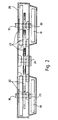
- Figures 2 and 3 show the interior of a link-up unit, for simplicity for an engine having two cylinder block modules, but clearly such a link-up unit can readily be modified in accordance with the invention to suit an engine having three cylinder block modules, as in Figure 1, or four or more cylinder block modules.
- the link-up unit of Figures 2 and 3 shows the crankshafts 16 of the two cylinder block modules coupled via clutches 18 and coaxial inner and outer shafts 20 to gear trains 22 which couple to an output drive shaft 24.
- Reference 26 denotes the back plate of the link-up unit.
- the clutches are automatically controlled by an engine management system so that either one or both cylinder block modules are coupled to the output shaft, depending on the variable power requirements of the engine when in use.
- Figure 4 shows an engine having three or more cylinder block modules of which, for simplicity, two such cylinder block modules 28 are shown bolted together at 30.
- the cylinder block modules could be integrally formed each with its crankcase.
- Figure 4a shows the versatility of the arrangement, in that according to requirements the cylinder block modules 28 can be interconnected in any desired positional relationship, in association with appropriate re-arrangement of the link-up unit.
- Figure 5 shows the engine of Figure 4 in side view, with the link-up unit 14 on the right.
- Figure 6 shows part of a cylinder block module, and more especially a preferred valve control system therefor. Instead of being open topped to receive a cylinder head and conventional camshaft controlled valves, the top of the module is closed, and fitted with slide valves 32 controlling the injection of fuel into the engine. The arrangement is especially suitable for a gas fuelled engine.
- FIGs 7a to 7d show detail of one of the slide valves.
- This comprises a valve housing 34 in which is incorporated a tapered valve slide 36 controlled by a cam follower 38 driven by cam 40 on the camshaft and acting against a spring or hydraulic damper 42.
- the valve slide 36 opens and closes apertures 44 bored in the top wall of the cylinder block module (see also Figure 6).
- the basic cylindrical block module can be built with two, three or four valves per cylinder, fitted on top with single or twin cams, or side fitted as a crossflow with twin cams.
- conventional valves driven by a conventional camshaft drive could be employed instead.
- Cam bearings, cam followers and valve slides etc. are all oil fed by oil lines pre-drilled in the valve housings, cylinder block and crankcase with return channels suitable for all engine mounting positions.
- the valves are provided on a machined face of the cylinder block to which the machined valve housing is bolted; a dowelled oil feed will line up the holes.
- the valve is hardened and has two tapers which holds the valve tightly closed with the spring or hydraulic pressure holding the plate to the tapers.
- the valve slide has an adjustable cam follower in front for adjustment and for operating the valve when pushed by the cam to open the port by aligning the hole in the valve plate, housing and cylinder port. On release, the valve slide is pushed back onto the tapers holding it closed. Servicing can be carried out by either unbolting the entire valve unit or removing the valve plate, in situ, by removing the spring cap and replacing any required parts.
- the illustrated link up unit is an enclosed gear train linked together, but could be fitted with a solenoid cut out on each of the intermediate gears, which could operate in the event of damage to any section.
- Each crankshaft is fitted with a clutch and sliding gear, but the latter is optional, depending on type of clutch used.
- a torque converter, fluid flywheel, or any other type of clutch can be employed.
- the gear train can be variable to suit requirements, and the output shaft be fitted in a variety of positions, e.g. high to lower the centre of gravity, and low in marine applications to permit shafts to be fitted in the keel.
- various numbers of output shafts can be used, depending on the number of crankshafts used.
- crankshafts will run at an identical speed, and to be stopped or brought back into synchronism as and when required.
- the optional layout of the engine enables designers to lower the centre of gravity, leading to greater stability and increased safety; also with hydraulic power the engine could be fitted in any position in order to improve space or accessibility, as well as eliminating the stress of torque.
- the casting may be manufactured of various materials, including some plastics to save weight and costs. As the crankshafts will be housed as single units capable of being bolted together, many savings can be made in production and design as well as in speed and ease of unit or part-unit replacement; also spares stockholding economies.
- the engine is capable of running on any fuel type for which the engine is built, liquid or gas, and by sump or external oil reservoir and pump, and the preferred valve system enables considerable space saving in the overall height of the unit, giving many design advantages. Moreover, as no head is used with this valve system, there is no risk of headgasket problems, and the valves can be changed simply.
- link up concept is also suitable for use in connecting gas turbine modules or electric power supplies, i.e. electric motors.
Landscapes
- Engineering & Computer Science (AREA)
- Mechanical Engineering (AREA)
- General Engineering & Computer Science (AREA)
- Chemical & Material Sciences (AREA)
- Combustion & Propulsion (AREA)
- Valve-Gear Or Valve Arrangements (AREA)
- Cylinder Crankcases Of Internal Combustion Engines (AREA)
- Devices For Conveying Motion By Means Of Endless Flexible Members (AREA)
- Control Of Throttle Valves Provided In The Intake System Or In The Exhaust System (AREA)
- Valve Device For Special Equipments (AREA)
- Transplanting Machines (AREA)
- Soil Working Implements (AREA)
- Catching Or Destruction (AREA)
- Output Control And Ontrol Of Special Type Engine (AREA)
- Control Of Electric Motors In General (AREA)
- Control Of Motors That Do Not Use Commutators (AREA)
- Arrangement Of Transmissions (AREA)
- Control Of Vehicle Engines Or Engines For Specific Uses (AREA)
- Vehicle Body Suspensions (AREA)
- Control Of Multiple Motors (AREA)
- Input Circuits Of Receivers And Coupling Of Receivers And Audio Equipment (AREA)
Applications Claiming Priority (3)
| Application Number | Priority Date | Filing Date | Title |
|---|---|---|---|
| GB9604769 | 1996-03-06 | ||
| GB9604769A GB2310894A (en) | 1996-03-06 | 1996-03-06 | Multi-engine drive unit |
| PCT/GB1997/000575 WO1997033072A1 (en) | 1996-03-06 | 1997-03-03 | Modular engine |
Publications (2)
| Publication Number | Publication Date |
|---|---|
| EP0885347A1 EP0885347A1 (en) | 1998-12-23 |
| EP0885347B1 true EP0885347B1 (en) | 2000-09-27 |
Family
ID=10789952
Family Applications (1)
| Application Number | Title | Priority Date | Filing Date |
|---|---|---|---|
| EP97905314A Expired - Lifetime EP0885347B1 (en) | 1996-03-06 | 1997-03-03 | Modular engine |
Country Status (13)
| Country | Link |
|---|---|
| US (1) | US6105542A (da) |
| EP (1) | EP0885347B1 (da) |
| JP (1) | JP2000506244A (da) |
| AT (1) | ATE196668T1 (da) |
| AU (1) | AU708943B2 (da) |
| CA (1) | CA2248373A1 (da) |
| DE (1) | DE69703202T2 (da) |
| DK (1) | DK0885347T3 (da) |
| ES (1) | ES2151718T3 (da) |
| GB (2) | GB2310894A (da) |
| GR (1) | GR3035015T3 (da) |
| PT (1) | PT885347E (da) |
| WO (1) | WO1997033072A1 (da) |
Families Citing this family (16)
| Publication number | Priority date | Publication date | Assignee | Title |
|---|---|---|---|---|
| GB2344378A (en) * | 1998-12-05 | 2000-06-07 | Rover Group | Modular i.c. engine |
| US20030133939A1 (en) | 2001-01-17 | 2003-07-17 | Genecraft, Inc. | Binding domain-immunoglobulin fusion proteins |
| US7754208B2 (en) | 2001-01-17 | 2010-07-13 | Trubion Pharmaceuticals, Inc. | Binding domain-immunoglobulin fusion proteins |
| US6904883B2 (en) * | 2002-04-15 | 2005-06-14 | Tecumseh Products Company | Modular internal combustion engines |
| WO2004065768A2 (en) * | 2003-01-22 | 2004-08-05 | Karem Abraham E | Fail-operational internal combustion engine |
| EP1627158B1 (en) * | 2003-05-28 | 2014-05-07 | The Boeing Company | Torque dividing gear drive system and method of driving an output gear |
| US6817326B1 (en) | 2003-09-22 | 2004-11-16 | Kevin J. Anibas | Valve system for internal combustion engines |
| RU2423381C2 (ru) | 2005-07-25 | 2011-07-10 | Трабьон Фармасьютикалз, Инк. | Снижение количества в-клеток с использованием cd37-специфических и cd20-специфических связывающих молекул |
| US7373909B2 (en) | 2005-09-23 | 2008-05-20 | Jp Scope Llc | Valve apparatus for an internal combustion engine |
| US8528511B2 (en) * | 2005-09-23 | 2013-09-10 | Jp Scope, Inc. | Variable travel valve apparatus for an internal combustion engine |
| NZ573646A (en) | 2006-06-12 | 2012-04-27 | Wyeth Llc | Single-chain multivalent binding proteins with effector function |
| US8087393B2 (en) * | 2007-05-18 | 2012-01-03 | Arrow Leads, Inc. | Zero float valve for internal combustion engine and method of operation thereof |
| US8360395B2 (en) * | 2008-11-07 | 2013-01-29 | Dragon America Motor Technologies, Inc. | Sliding valve assembly |
| US8707929B2 (en) | 2011-07-28 | 2014-04-29 | Pratt & Whitney Canada Corp. | Multi-rotor rotary engine architecture |
| WO2017053469A2 (en) | 2015-09-21 | 2017-03-30 | Aptevo Research And Development Llc | Cd3 binding polypeptides |
| MX2019002668A (es) | 2016-09-09 | 2020-08-13 | Charles Price | Aparato de válvulas de desplazamiento variable para un motor de combustión interna. |
Citations (2)
| Publication number | Priority date | Publication date | Assignee | Title |
|---|---|---|---|---|
| US2838913A (en) * | 1950-07-15 | 1958-06-17 | Gen Motors Corp | Aircraft power system and clutch control therefor |
| GB2102066A (en) * | 1981-07-21 | 1983-01-26 | Kronogard Sven Olof | I.C. engine with a split crankshaft |
Family Cites Families (29)
| Publication number | Priority date | Publication date | Assignee | Title |
|---|---|---|---|---|
| US1492587A (en) * | 1922-05-24 | 1924-05-06 | Internat Process And Engineeri | Engine |
| FR572174A (fr) * | 1923-10-23 | 1924-06-02 | Moteur à explosions sans soupapes | |
| US1537248A (en) * | 1923-12-13 | 1925-05-12 | Thomas J Maloney | Internal-combustion engine |
| US1574686A (en) * | 1925-03-23 | 1926-02-23 | Petticore Anthony | Engine |
| US1781176A (en) * | 1927-03-29 | 1930-11-11 | Grube Silent Motors Inc | Engine valve |
| GB764005A (en) * | 1953-07-07 | 1956-12-19 | Weser Ag | Improvements in or relating to ship propelling installations |
| AT247408B (de) * | 1963-11-18 | 1966-06-10 | Voith Getriebe Kg | Kraftübertragungseinrichtung mit mindestens zwei Strömungsgetrieben, insbesondere für ein Schienentriebfahrzeug |
| US3332404A (en) * | 1965-02-15 | 1967-07-25 | Charles L Lovercheck | Dual engine |
| GB1172500A (en) * | 1966-12-22 | 1969-12-03 | Ford Motor Co | Vehicle Engine Arrangement |
| US3390670A (en) * | 1967-06-26 | 1968-07-02 | Ametek Inc | Combined engines |
| GB1216558A (en) * | 1967-06-29 | 1970-12-23 | Goetaverken Ab | Improvements in or relating to power plants |
| DE2044943A1 (de) * | 1970-09-11 | 1972-03-16 | Carbon, Theo, DipL-Ing., 8720 Schweinfurt; Hutter, Friedrich, 8721 Niederwerrn | Hubkolbenmaschine nach dem Baukastenprinzip |
| SE7611617L (sv) * | 1976-10-20 | 1978-04-21 | Kronogard Sven Olof | Fordonsmaskineri |
| DE2946117C2 (de) * | 1979-11-15 | 1987-04-30 | Volkswagen AG, 3180 Wolfsburg | Motor-Getriebe-Anordnung für Fahrzeuge, insbesondere Kraftfahrzeuge |
| SE8006807L (sv) * | 1980-09-29 | 1982-03-30 | United Motor & Transmissions A | Fordonsmotor |
| FR2491132A1 (fr) * | 1980-09-29 | 1982-04-02 | Kronogard Sven Olof | Installation de propulsion de vehicule comprenant plusieurs cylindres de puissance differente |
| JPS5793655A (en) * | 1980-11-29 | 1982-06-10 | Fuji Heavy Ind Ltd | Connecting method for internal combustion engine having plural power sources |
| DE3045093A1 (de) * | 1980-11-29 | 1982-07-01 | Daimler-Benz Ag, 7000 Stuttgart | Mehrfachanordnung von brennkraftmaschinen |
| JPS5842859A (ja) * | 1981-09-09 | 1983-03-12 | Fuji Heavy Ind Ltd | 複数動力源を有する内燃機関のクラツチ機構 |
| JPS5844246A (ja) * | 1981-09-09 | 1983-03-15 | Fuji Heavy Ind Ltd | 複数動力源の制御方法 |
| WO1985001548A1 (en) * | 1983-09-28 | 1985-04-11 | Borislaw Ivanov | Stator-rotor piston internal combustion engine |
| EP0184685A3 (en) * | 1984-12-13 | 1987-04-08 | KANIUT, Herbert Maximilian | Split-engine for motor-vehicles, with a divided crankshaft, and an engine cross-shaft for auxiliary-drives |
| US4714060A (en) * | 1986-02-04 | 1987-12-22 | R K W Industries, Inc. | Composite engine |
| US4765287A (en) * | 1987-11-02 | 1988-08-23 | Taylor Bill A | Slide valve apparatus for internal combustion engine |
| IT1211518B (it) * | 1987-11-12 | 1989-11-03 | Offmar S N C Di Matta Emiliano | Motore particolarmente per velivoli ultraleggeri |
| US5228294A (en) * | 1988-11-30 | 1993-07-20 | Murray Jerome L | Rotary internal combustion engine |
| US5647309A (en) * | 1994-12-01 | 1997-07-15 | Avery; Alfred J. | Internal combustion engine firing system |
| US5694890A (en) * | 1996-10-07 | 1997-12-09 | Yazdi; Kamran | Internal combustion engine with sliding valves |
| AUPO319796A0 (en) * | 1996-10-24 | 1996-11-14 | Williames, Geoffrey Allan | Vehicle powertrains |
-
1996
- 1996-03-06 GB GB9604769A patent/GB2310894A/en not_active Withdrawn
-
1997
- 1997-03-03 EP EP97905314A patent/EP0885347B1/en not_active Expired - Lifetime
- 1997-03-03 WO PCT/GB1997/000575 patent/WO1997033072A1/en not_active Ceased
- 1997-03-03 CA CA002248373A patent/CA2248373A1/en not_active Abandoned
- 1997-03-03 PT PT97905314T patent/PT885347E/pt unknown
- 1997-03-03 DK DK97905314T patent/DK0885347T3/da active
- 1997-03-03 AU AU22239/97A patent/AU708943B2/en not_active Ceased
- 1997-03-03 AT AT97905314T patent/ATE196668T1/de not_active IP Right Cessation
- 1997-03-03 ES ES97905314T patent/ES2151718T3/es not_active Expired - Lifetime
- 1997-03-03 GB GB9818407A patent/GB2326445B/en not_active Expired - Fee Related
- 1997-03-03 DE DE69703202T patent/DE69703202T2/de not_active Expired - Fee Related
- 1997-03-03 JP JP9531556A patent/JP2000506244A/ja not_active Ceased
- 1997-03-03 US US09/125,923 patent/US6105542A/en not_active Expired - Fee Related
-
2000
- 2000-12-06 GR GR20000402706T patent/GR3035015T3/el not_active IP Right Cessation
Patent Citations (2)
| Publication number | Priority date | Publication date | Assignee | Title |
|---|---|---|---|---|
| US2838913A (en) * | 1950-07-15 | 1958-06-17 | Gen Motors Corp | Aircraft power system and clutch control therefor |
| GB2102066A (en) * | 1981-07-21 | 1983-01-26 | Kronogard Sven Olof | I.C. engine with a split crankshaft |
Also Published As
| Publication number | Publication date |
|---|---|
| ATE196668T1 (de) | 2000-10-15 |
| GB9818407D0 (en) | 1998-10-21 |
| PT885347E (pt) | 2001-03-30 |
| GB2310894A (en) | 1997-09-10 |
| GB2326445A (en) | 1998-12-23 |
| AU708943B2 (en) | 1999-08-19 |
| DE69703202T2 (de) | 2001-04-26 |
| EP0885347A1 (en) | 1998-12-23 |
| DE69703202D1 (de) | 2000-11-02 |
| CA2248373A1 (en) | 1997-09-12 |
| ES2151718T3 (es) | 2001-01-01 |
| GB2326445B (en) | 2000-02-09 |
| US6105542A (en) | 2000-08-22 |
| GR3035015T3 (en) | 2001-03-30 |
| DK0885347T3 (da) | 2001-01-02 |
| GB9604769D0 (en) | 1996-05-08 |
| WO1997033072A1 (en) | 1997-09-12 |
| JP2000506244A (ja) | 2000-05-23 |
| AU2223997A (en) | 1997-09-22 |
Similar Documents
| Publication | Publication Date | Title |
|---|---|---|
| EP0885347B1 (en) | Modular engine | |
| US6789522B2 (en) | Engine for aeronautical applications | |
| US4834219A (en) | Oil pump for internal combustion engine disposed concentrically about the transmission mainshaft | |
| US2963006A (en) | Two cycle super charged internal combustion engine | |
| US6209495B1 (en) | Compound two stroke engine | |
| US3528394A (en) | Internal combustion engine | |
| US5876188A (en) | Oil pump arrangement for four-cycle outboard motor | |
| EP0857861A1 (en) | Engine | |
| JPS5825518A (ja) | 自動車用エンジン | |
| US3094190A (en) | Internal combustion engine | |
| GB2127897A (en) | Hydraulic drive charging compressor for internal combustion engines | |
| US3145695A (en) | Cylinder block for an internal combustion engine | |
| US2607328A (en) | Diesel motor | |
| US2334917A (en) | Opposed-piston engine | |
| JP4058926B2 (ja) | 船外機の潤滑装置 | |
| US20050011478A1 (en) | Engine with dual oiling and hydraulic valves | |
| US6550448B1 (en) | Engine throttle valve linkage | |
| CN112177773B (zh) | 一种航空活塞发动机 | |
| CN213205831U (zh) | 一种航空活塞发动机机体 | |
| JPH0692725B2 (ja) | エンジンのオイルパン装置 | |
| US6705269B2 (en) | Four-cycle engine | |
| US2390960A (en) | Internal-combustion engine | |
| SU1576694A1 (ru) | Двигатель внутреннего сгорани | |
| CN213360249U (zh) | 一种航空活塞发动机 | |
| JP2516760B2 (ja) | エンジンにおける点火プラグ取付装置 |
Legal Events
| Date | Code | Title | Description |
|---|---|---|---|
| PUAI | Public reference made under article 153(3) epc to a published international application that has entered the european phase |
Free format text: ORIGINAL CODE: 0009012 |
|
| 17P | Request for examination filed |
Effective date: 19980826 |
|
| AK | Designated contracting states |
Kind code of ref document: A1 Designated state(s): AT BE CH DE DK ES FI FR GB GR IE IT LI LU NL PT SE |
|
| 17Q | First examination report despatched |
Effective date: 19990303 |
|
| GRAG | Despatch of communication of intention to grant |
Free format text: ORIGINAL CODE: EPIDOS AGRA |
|
| GRAG | Despatch of communication of intention to grant |
Free format text: ORIGINAL CODE: EPIDOS AGRA |
|
| GRAH | Despatch of communication of intention to grant a patent |
Free format text: ORIGINAL CODE: EPIDOS IGRA |
|
| GRAH | Despatch of communication of intention to grant a patent |
Free format text: ORIGINAL CODE: EPIDOS IGRA |
|
| GRAA | (expected) grant |
Free format text: ORIGINAL CODE: 0009210 |
|
| AK | Designated contracting states |
Kind code of ref document: B1 Designated state(s): AT BE CH DE DK ES FI FR GB GR IE IT LI LU NL PT SE |
|
| REF | Corresponds to: |
Ref document number: 196668 Country of ref document: AT Date of ref document: 20001015 Kind code of ref document: T |
|
| REG | Reference to a national code |
Ref country code: CH Ref legal event code: EP |
|
| ITF | It: translation for a ep patent filed | ||
| REG | Reference to a national code |
Ref country code: IE Ref legal event code: FG4D |
|
| REF | Corresponds to: |
Ref document number: 69703202 Country of ref document: DE Date of ref document: 20001102 |
|
| REG | Reference to a national code |
Ref country code: CH Ref legal event code: NV Representative=s name: PATENTANWALTSBUERO FELDMANN AG |
|
| REG | Reference to a national code |
Ref country code: ES Ref legal event code: FG2A Ref document number: 2151718 Country of ref document: ES Kind code of ref document: T3 |
|
| REG | Reference to a national code |
Ref country code: DK Ref legal event code: T3 |
|
| ET | Fr: translation filed | ||
| PG25 | Lapsed in a contracting state [announced via postgrant information from national office to epo] |
Ref country code: LU Free format text: LAPSE BECAUSE OF NON-PAYMENT OF DUE FEES Effective date: 20010303 |
|
| REG | Reference to a national code |
Ref country code: PT Ref legal event code: SC4A Free format text: AVAILABILITY OF NATIONAL TRANSLATION Effective date: 20001206 |
|
| PLBE | No opposition filed within time limit |
Free format text: ORIGINAL CODE: 0009261 |
|
| STAA | Information on the status of an ep patent application or granted ep patent |
Free format text: STATUS: NO OPPOSITION FILED WITHIN TIME LIMIT |
|
| 26N | No opposition filed | ||
| REG | Reference to a national code |
Ref country code: GB Ref legal event code: IF02 |
|
| PGFP | Annual fee paid to national office [announced via postgrant information from national office to epo] |
Ref country code: AT Payment date: 20030206 Year of fee payment: 7 |
|
| PGFP | Annual fee paid to national office [announced via postgrant information from national office to epo] |
Ref country code: DK Payment date: 20030211 Year of fee payment: 7 |
|
| PGFP | Annual fee paid to national office [announced via postgrant information from national office to epo] |
Ref country code: GB Payment date: 20030212 Year of fee payment: 7 |
|
| PGFP | Annual fee paid to national office [announced via postgrant information from national office to epo] |
Ref country code: FI Payment date: 20030213 Year of fee payment: 7 |
|
| PGFP | Annual fee paid to national office [announced via postgrant information from national office to epo] |
Ref country code: CH Payment date: 20030214 Year of fee payment: 7 Ref country code: SE Payment date: 20030214 Year of fee payment: 7 |
|
| PGFP | Annual fee paid to national office [announced via postgrant information from national office to epo] |
Ref country code: NL Payment date: 20030217 Year of fee payment: 7 |
|
| PGFP | Annual fee paid to national office [announced via postgrant information from national office to epo] |
Ref country code: PT Payment date: 20030219 Year of fee payment: 7 |
|
| PGFP | Annual fee paid to national office [announced via postgrant information from national office to epo] |
Ref country code: BE Payment date: 20030305 Year of fee payment: 7 |
|
| PG25 | Lapsed in a contracting state [announced via postgrant information from national office to epo] |
Ref country code: IE Free format text: LAPSE BECAUSE OF NON-PAYMENT OF DUE FEES Effective date: 20040303 Ref country code: GB Free format text: LAPSE BECAUSE OF NON-PAYMENT OF DUE FEES Effective date: 20040303 Ref country code: FI Free format text: LAPSE BECAUSE OF NON-PAYMENT OF DUE FEES Effective date: 20040303 Ref country code: AT Free format text: LAPSE BECAUSE OF NON-PAYMENT OF DUE FEES Effective date: 20040303 |
|
| PG25 | Lapsed in a contracting state [announced via postgrant information from national office to epo] |
Ref country code: SE Free format text: LAPSE BECAUSE OF NON-PAYMENT OF DUE FEES Effective date: 20040304 |
|
| PGFP | Annual fee paid to national office [announced via postgrant information from national office to epo] |
Ref country code: FR Payment date: 20040311 Year of fee payment: 8 |
|
| PGFP | Annual fee paid to national office [announced via postgrant information from national office to epo] |
Ref country code: DE Payment date: 20040330 Year of fee payment: 8 Ref country code: GR Payment date: 20040330 Year of fee payment: 8 |
|
| PG25 | Lapsed in a contracting state [announced via postgrant information from national office to epo] |
Ref country code: LI Free format text: LAPSE BECAUSE OF NON-PAYMENT OF DUE FEES Effective date: 20040331 Ref country code: DK Free format text: LAPSE BECAUSE OF NON-PAYMENT OF DUE FEES Effective date: 20040331 Ref country code: CH Free format text: LAPSE BECAUSE OF NON-PAYMENT OF DUE FEES Effective date: 20040331 Ref country code: BE Free format text: LAPSE BECAUSE OF NON-PAYMENT OF DUE FEES Effective date: 20040331 |
|
| PGFP | Annual fee paid to national office [announced via postgrant information from national office to epo] |
Ref country code: ES Payment date: 20040407 Year of fee payment: 8 |
|
| BERE | Be: lapsed |
Owner name: *EFFORD CLIVE WILLIAM Effective date: 20040331 |
|
| PG25 | Lapsed in a contracting state [announced via postgrant information from national office to epo] |
Ref country code: NL Free format text: LAPSE BECAUSE OF NON-PAYMENT OF DUE FEES Effective date: 20041001 |
|
| PG25 | Lapsed in a contracting state [announced via postgrant information from national office to epo] |
Ref country code: PT Free format text: LAPSE BECAUSE OF NON-PAYMENT OF DUE FEES Effective date: 20041015 |
|
| GBPC | Gb: european patent ceased through non-payment of renewal fee | ||
| EUG | Se: european patent has lapsed | ||
| REG | Reference to a national code |
Ref country code: CH Ref legal event code: PL |
|
| REG | Reference to a national code |
Ref country code: PT Ref legal event code: MM4A Free format text: LAPSE DUE TO NON-PAYMENT OF FEES Effective date: 20040930 |
|
| NLV4 | Nl: lapsed or anulled due to non-payment of the annual fee |
Effective date: 20041001 |
|
| REG | Reference to a national code |
Ref country code: IE Ref legal event code: MM4A |
|
| PG25 | Lapsed in a contracting state [announced via postgrant information from national office to epo] |
Ref country code: IT Free format text: LAPSE BECAUSE OF NON-PAYMENT OF DUE FEES;WARNING: LAPSES OF ITALIAN PATENTS WITH EFFECTIVE DATE BEFORE 2007 MAY HAVE OCCURRED AT ANY TIME BEFORE 2007. THE CORRECT EFFECTIVE DATE MAY BE DIFFERENT FROM THE ONE RECORDED. Effective date: 20050303 |
|
| PG25 | Lapsed in a contracting state [announced via postgrant information from national office to epo] |
Ref country code: ES Free format text: LAPSE BECAUSE OF NON-PAYMENT OF DUE FEES Effective date: 20050304 |
|
| PG25 | Lapsed in a contracting state [announced via postgrant information from national office to epo] |
Ref country code: DE Free format text: LAPSE BECAUSE OF NON-PAYMENT OF DUE FEES Effective date: 20051001 |
|
| PG25 | Lapsed in a contracting state [announced via postgrant information from national office to epo] |
Ref country code: GR Free format text: LAPSE BECAUSE OF NON-PAYMENT OF DUE FEES Effective date: 20051004 |
|
| PG25 | Lapsed in a contracting state [announced via postgrant information from national office to epo] |
Ref country code: FR Free format text: LAPSE BECAUSE OF NON-PAYMENT OF DUE FEES Effective date: 20051130 |
|
| REG | Reference to a national code |
Ref country code: FR Ref legal event code: ST Effective date: 20051130 |
|
| REG | Reference to a national code |
Ref country code: ES Ref legal event code: FD2A Effective date: 20050304 |
|
| PGFP | Annual fee paid to national office [announced via postgrant information from national office to epo] |
Ref country code: IE Payment date: 20030331 Year of fee payment: 7 |
|
| PG25 | Lapsed in a contracting state [announced via postgrant information from national office to epo] |
Ref country code: PT Free format text: LAPSE BECAUSE OF NON-PAYMENT OF DUE FEES Effective date: 20040303 |