EP0885384B1 - Blasen-detektor - Google Patents
Blasen-detektor Download PDFInfo
- Publication number
- EP0885384B1 EP0885384B1 EP97908626A EP97908626A EP0885384B1 EP 0885384 B1 EP0885384 B1 EP 0885384B1 EP 97908626 A EP97908626 A EP 97908626A EP 97908626 A EP97908626 A EP 97908626A EP 0885384 B1 EP0885384 B1 EP 0885384B1
- Authority
- EP
- European Patent Office
- Prior art keywords
- conduit
- light beam
- fluid
- detector means
- detector
- Prior art date
- Legal status (The legal status is an assumption and is not a legal conclusion. Google has not performed a legal analysis and makes no representation as to the accuracy of the status listed.)
- Expired - Lifetime
Links
- 239000012530 fluid Substances 0.000 claims description 39
- 230000001419 dependent effect Effects 0.000 claims description 4
- 238000012544 monitoring process Methods 0.000 claims description 2
- 239000007788 liquid Substances 0.000 description 12
- 231100001261 hazardous Toxicity 0.000 description 3
- 230000008859 change Effects 0.000 description 2
- 230000008034 disappearance Effects 0.000 description 2
- 230000007257 malfunction Effects 0.000 description 2
- 230000004044 response Effects 0.000 description 2
- 230000032258 transport Effects 0.000 description 2
- 230000008901 benefit Effects 0.000 description 1
- 230000017531 blood circulation Effects 0.000 description 1
- 238000010276 construction Methods 0.000 description 1
- 238000001514 detection method Methods 0.000 description 1
- 238000006073 displacement reaction Methods 0.000 description 1
- 238000005516 engineering process Methods 0.000 description 1
- 238000001802 infusion Methods 0.000 description 1
- 239000000463 material Substances 0.000 description 1
- 239000000203 mixture Substances 0.000 description 1
- 230000001960 triggered effect Effects 0.000 description 1
- XLYOFNOQVPJJNP-UHFFFAOYSA-N water Substances O XLYOFNOQVPJJNP-UHFFFAOYSA-N 0.000 description 1
Images
Classifications
-
- G—PHYSICS
- G01—MEASURING; TESTING
- G01N—INVESTIGATING OR ANALYSING MATERIALS BY DETERMINING THEIR CHEMICAL OR PHYSICAL PROPERTIES
- G01N21/00—Investigating or analysing materials by the use of optical means, i.e. using sub-millimetre waves, infrared, visible or ultraviolet light
- G01N21/17—Systems in which incident light is modified in accordance with the properties of the material investigated
- G01N21/41—Refractivity; Phase-affecting properties, e.g. optical path length
-
- G—PHYSICS
- G01—MEASURING; TESTING
- G01N—INVESTIGATING OR ANALYSING MATERIALS BY DETERMINING THEIR CHEMICAL OR PHYSICAL PROPERTIES
- G01N21/00—Investigating or analysing materials by the use of optical means, i.e. using sub-millimetre waves, infrared, visible or ultraviolet light
- G01N21/84—Systems specially adapted for particular applications
- G01N21/85—Investigating moving fluids or granular solids
Definitions
- the invention relates to a bubble detector of the kind defined in the preamble of the following Claim 1.
- FR-A1-2 660 755 discloses a bubble detector that includes a conduit through which a first fluid having a first refractive index passes, a light source which directs a light beam through a first transparent wall part of the conduit, through the conduit cavity, and out through a second transparent wall part of said conduit, and a detector means which receives the light beam after it has passed through the conduit and the first fluid present therein. It is also disclosed in FR-A1-2 660 755 that the light beam shall be directed in a plane normal to the axis of the circular-cylindrical conduit and be directed non-diametrically through said conduit.
- the object of the present invention is to reduce or eliminate at least one of these drawbacks.
- the dependent Claims define further embodiments of the detector.
- the invention is based on the fundamental concept that the two transparent conduit wall-parts that are trans-illuminated by the light beam shall be essentially flat and parallel and that the light beam is directed through the conduit at an oblique angle, e.g. 45 degrees, to the nearest plane of the trans-illuminated wall-part, so that the light beam will be broken into different paths depending on whether the beam in the conduit passes through the first fluid or through bubbles of a second fluid having a different refractive index.
- the detector means is therewith adapted to be impinged upon by the light beam exiting from the conduit independently of refractive index for the fluid or fluid mixture present between the two conduit wall-parts.
- the detector means is adapted to deliver an output signal that depends on the position at which the light beam meets the detector means, so as to enable the presence of bubbles of said second fluid in said first fluid to be identified by corresponding variations in the detector output signal.
- the detector means includes a difference photodiode which delivers a signal that depends on the position at which the light beam meets the diode surface.
- a detector means of this nature can be readily calibrated; the first fluid, e.g. a liquid, can be passed through the conduit while ensuring that the first fluid is free from bubbles or the like.
- the signal that defines a bubble-free state of the first fluid is noted at the same time.
- a given deviation from this output signal will indicate a change in the refractive index of the medium in the conduit, that the detector means is malfunctioning, or that the alignment of the light source in relation to the conduit and/or the detector has been changed. Because the change in output signal is the result of a displacement in the distance of the position of contact of the light beam from the calibrating position, there will always be obtained an output signal from the detector means provided that the light source is operative and said arrangement has not broken down.
- the detector means may include mutually separated, simple photodetectors instead of a difference photoelectrode.
- one photodetector is placed in a position in which it will be met by the light beam when passing through a bubble-free first fluid, and the other detector is placed in a position in which it will only be met by the light beam when said beam passes through a fluid in the conduit that has a different refractive index to said first fluid.
- the conduit When the conduit is circular-cylindrical, the conditions whereby the conduit wall-parts trans-illuminated by the light beam are essentially planar and parallel can still be established, provided that it is ensured that the beam is narrow and cuts the conduit axis in its various refractive-index dependent paths.
- the path of the light beam will preferably lie in a plane that includes the conduit axis.
- trans-illuminated wall-parts are preferably plane-parallel wall parts, so that the position at which the light beam meets said parts is not critical.
- positive information is obtained from the detector means in the form of an output signal both when the conduit transports bubble-free fluid and when bubbles are present in the fluid flow, or when solely gas is present in the conduit.
- the inventive detector means can be used to control the flow of fluid through the conduit and/or to trigger an alarm when bubbles appear, or when the detector output signal disappears completely.
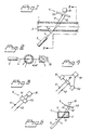
- the inventive bubble detector includes a light permeable conduit 1, whose longitudinal axis is referenced 2. Liquid flows through the conduit 1 in the direction of its axis 2.
- the bubble detector functions to detect a gas bubble, such as an air bubble, in the liquid flow, said gas and liquid being assumed to have mutually different refractive indexes.
- a light source 3 directs a light beam 4 through the conduit 1 at an oblique angle ⁇ to the axis 2.
- oblique is meant an angle ⁇ that is greater than 0 and smaller than 90°, preferably an angle in the range of 30-60°, for instance about 45°.
- the conduit 1 shall be permeable to light at the two wall-parts 11, 12 through which the beam 4 passes.
- the light beam 4 will take different paths through the conduit 1, depending on the refractive index of the medium located in the path of the light beam within the conduit 1.
- the light beam 4 will take the path 41 when the fluid in the conduit has essentially the same refractive index as the material from which the conduit 1 is made, as in the case when a liquid, such as water, flows through the conduit 1.
- the light beam 4 will take the path 42 in Fig. 1 when the fluid in the conduit has a refractive index that is significantly lower than that of a liquid, for instance when the fluid is air.
- the conduit 1 has a cross-sectional size that corresponds to a bubble size that is considered to be dangerous or harmful, such that a bubble will be unable to pass through the conduit 1 by the side of the light beam 4; 41, 42.
- the detector means 5 that receives the beams 41, 42 includes a detector 53, preferably a conventional difference photodiode, which delivers a signal whose magnitude depends on the position of impingement of the beam along the surface of the diode 53.
- a difference photodiode which delivers a signal whose magnitude depends on the position of impingement of the beam along the surface of the diode 53.
- the bubble detector can thus be easily calibrated, by noting the output signal obtained in respect of a bubble-free liquid that has a known refractive index.
- the refractive index of an unknown (bubble-free) fluid can be determined by the output signal obtained in respect thereof, this output signal thus being dependent on the position of impingement of the beam.
- the conduit 1 has a circular-cylindrical configuration. It is important in this case that the beams 4, 41, 42 intersect the conduit axis 2 so that the trans-illuminated wall-parts 11, 12 are planar and parallel in practice. However, when the conduit 1 is configured so as to have actually two flat plane-parallel wall-parts 11, 12 of uniform thickness, as illustrated in Fig. 5, the throughflow direction/axis 2 of the conduit 1 and the light beams 4, 41, 42 need not, of course, lie in a common plane, as will be evident from a study of Fig. 5.
- Fig. 3 illustrates a simplified embodiment of the invention in which the detector means 5 includes two separated detectors 51, 52 that are positioned to receive the beam 41 and the beam 42 respectively.
- a prism 60 which functions to deflect the beams 41, 42 to the two detectors 51, 52 may be provided with the intention of obtaining a sharper definition between the two detectors 51, 52.
- the inventive arrangement thus obtains a significant redundancy. Because the detector means (or always at least one of the detectors 51, 52) will always deliver an output signal in response to an operable light source 3, there is immediately obtained an indication when the light source 3 malfunctions. An alarm indication is also given when the detector means 53 or one of the detectors 51, 52 has no output signal, this alarm indication being given immediately when the light source or the detector means malfunctions in some way or another.
- the illustrated arrangement includes a monitoring unit which functions to control the transport of liquid through the conduit 1, for instance by closing a valve in the conduit in the event of an alarm indication.
- the unit may conveniently include an alarm means that is triggered in response to an alarm indication.
- the invention finds general use in conjunction with the transportation of fluid through a conduit where it is important that fluid transportation can be stopped or that at least an alarm of some kind is generated when the refractive index of the fluid changes, such as when the fluid is a liquid that may not contain bubbles or be replaced with gas.
- the invention is therefore particularly useful in conjunction with the infusion of fluids to the blood circulation of the human body.
- the conduit 1 will preferably have an inner diameter that is at maximum essentially equal to a bubble size that is considered hazardous, so that the beam 4 will always take the path 42 when a hazardous bubble passes through the conduit.
Landscapes
- General Health & Medical Sciences (AREA)
- Life Sciences & Earth Sciences (AREA)
- Chemical & Material Sciences (AREA)
- Analytical Chemistry (AREA)
- Biochemistry (AREA)
- Immunology (AREA)
- General Physics & Mathematics (AREA)
- Health & Medical Sciences (AREA)
- Pathology (AREA)
- Physics & Mathematics (AREA)
- Investigating Or Analysing Materials By Optical Means (AREA)
- Measurement Of Levels Of Liquids Or Fluent Solid Materials (AREA)
- Investigating Materials By The Use Of Optical Means Adapted For Particular Applications (AREA)
- Geophysics And Detection Of Objects (AREA)
Claims (5)
- Blasendetektor mit einer Leitung (1), bestimmt für einen Durchfluß eines ersten Fluids mit einer ersten Brechungszahl, einer einzelnen Lichtquelle (3), die einen Lichtstrahl (4; 41, 42) durch einen transparenten Leitungswandteil (12) und durch den Leitungshohlraum und heraus durch einen zweiten transparenten Leitungswandteil hindurchleitet, und mit einer Detektoreinrichtung (5; 51, 52, 53), die geeignet ist, den Lichtstrahl (4, 41) zu empfangen, wenn der Strahl durch die Leitung und das erste Fluid in dieser hindurchgelaufen ist, wobei die beiden einander gegenüberliegenden transparenten Wandteile (12, 11) der Leitung (1), die durch den Lichtstrahl durchleuchtet werden, im wesentlichen eben und parallel sind, die einzelne Lichtquelle (3) geeignet ist, den Lichtstrahl (4) in einem schrägen Winkel (α) auf den proximalen transparenten Leitungswandteil (12) zu richten, so daß der Lichtstrahl in verschiedene Wege (41, 42) gebrochen wird, in Abhängigkeit davon, ob der Strahl das erste Fluid oder ein zweites leitungsgeführtes Fluid mit einer anderen Brechungszahl, wie etwa eine Blase, durchläuft, die Detektoreinrichtung (5; 53; 51, 52) geeignet ist, von dem aus der Leitung (1) austretenden Lichtstrahl ungeachtet der Brechungszahlen der Fluids beaufschlagt zu werden, und die Detektoreinrichtung (5; 53; 51, 52) geeignet ist, ein Ausgangssignal abzugeben, das von der Beaufschlagungsposition des Lichtstrahls (41, 42) auf der Detektoreinrichtung abhängig ist, um so das Auftreten von Blasen im ersten Fluid identifizieren zu können.
- Detektor nach Anspruch 1, dadurch gekennzeichnet, daß die Leitung allgemein zylindrisch, vorzugsweise kreiszylindrisch, ist und daß die von der Lichtquelle (3) ausgehenden Lichtstrahlen (4, 41, 42) und die Leitungsachse (2) in einer gemeinsamen Ebene liegen.
- Detektor nach Anspruch 1 oder 2, dadurch gekennzeichnet, daß die Detektoreinrichtung geeignet ist, einen Alarm auszulösen und/oder den Transport des ersten Fluids durch die Leitung (1) zu stoppen, wenn die Beaufschlagungsposition des Lichtstrahls auf der Detektoreinrichtung von der Beaufschlagungsposition abweicht, die dem durch ein blasenfreies erstes Fluid in der Leitung hindurchgehenden Lichtstrahl entspricht.
- Detektor nach einem der Ansprüche 1 bis 3, dadurch gekennzeichnet, daß die Detektoreinrichtung (5; 53; 51, 52) mit einer Überwachungslogik gekoppelt ist, die so arbeitet, daß ein Alarm ausgelöst und/oder der Transport von Fluid durch die Leitung (1) gestoppt wird, wenn das Ausgangssignal ausbleibt.
- Detektor nach einem der Ansprüche 1 bis 4, dadurch gekennzeichnet, daß die Detektoreinrichtung eine Differenzphotodiode (53) ist, die ein Ausgangssignal liefert, das von der Beaufschlagungsposition des Lichtstrahls (41, 42) auf der Diodenoberfläche abhängig ist.
Applications Claiming Priority (3)
| Application Number | Priority Date | Filing Date | Title |
|---|---|---|---|
| SE9600891A SE506546C2 (sv) | 1996-03-07 | 1996-03-07 | Bubbeldetektor |
| SE9600891 | 1996-03-07 | ||
| PCT/SE1997/000395 WO1997033154A1 (en) | 1996-03-07 | 1997-03-07 | A bubble detector |
Publications (2)
| Publication Number | Publication Date |
|---|---|
| EP0885384A1 EP0885384A1 (de) | 1998-12-23 |
| EP0885384B1 true EP0885384B1 (de) | 2006-08-30 |
Family
ID=20401705
Family Applications (1)
| Application Number | Title | Priority Date | Filing Date |
|---|---|---|---|
| EP97908626A Expired - Lifetime EP0885384B1 (de) | 1996-03-07 | 1997-03-07 | Blasen-detektor |
Country Status (7)
| Country | Link |
|---|---|
| US (1) | US6111263A (de) |
| EP (1) | EP0885384B1 (de) |
| JP (1) | JP2000506271A (de) |
| AU (1) | AU2049497A (de) |
| DE (1) | DE69736587T2 (de) |
| SE (1) | SE506546C2 (de) |
| WO (1) | WO1997033154A1 (de) |
Families Citing this family (16)
| Publication number | Priority date | Publication date | Assignee | Title |
|---|---|---|---|---|
| EP0982593B1 (de) * | 1998-08-17 | 2005-12-07 | F. Hoffmann-La Roche Ag | Verfahren zur Ueberwachung von Pipettiervorgängen |
| GB0417337D0 (en) * | 2004-08-04 | 2004-09-08 | Chu Andrew C | Low cost air bubble detector and alarm system for fluid administrative applications |
| RU2285918C1 (ru) * | 2005-09-21 | 2006-10-20 | Федеральное государственное образовательное учреждение высшего профессионального образования Дальневосточный государственный технический рыбохозяйственный университет | Способ исследования смазочных материалов и устройство для его осуществления |
| US20070141410A1 (en) * | 2005-12-15 | 2007-06-21 | Matsushita Electric Industrial Co., Ltd. | Direct oxidation fuel cell system |
| CN100366304C (zh) * | 2005-12-22 | 2008-02-06 | 李力 | 便携式医用输液报警装置 |
| US8004683B2 (en) * | 2007-10-11 | 2011-08-23 | Ecolab Usa Inc. | Optical product detection sensor |
| US7924424B2 (en) * | 2007-10-11 | 2011-04-12 | Ecolab Usa Inc. | Optical product detection sensor |
| KR101029902B1 (ko) * | 2008-12-30 | 2011-04-18 | 한국항공우주연구원 | 유체 식별 장치 및 방법 |
| JP5296015B2 (ja) * | 2010-06-22 | 2013-09-25 | 株式会社日立ハイテクノロジーズ | 自動分析装置 |
| WO2013162616A1 (en) * | 2012-04-27 | 2013-10-31 | Intel Corporation | Metrology and methods for detection of liquid |
| FR3003948B1 (fr) * | 2013-03-29 | 2016-02-05 | Centre Nat Rech Scient | Procede de detection d'elements disperses circulant a travers un tube capillaire, et appareil associe |
| JP6236736B2 (ja) * | 2013-07-29 | 2017-11-29 | 三菱ケミカル株式会社 | 製膜原液の異常検知装置及び異常検知方法 |
| DE102015117638A1 (de) * | 2015-10-16 | 2017-04-20 | Endress+Hauser Conducta Gmbh+Co. Kg | Verfahren zur Dosierung einer Flüssigkeit in einem nasschemischen Analysegerät zur Bestimmung eines Parameters einer Flüssigkeitsprobe |
| US10843152B2 (en) * | 2017-08-29 | 2020-11-24 | Delaware Capital Formation, Inc. | Out-of-product detection using optical sensors |
| CN114796730B (zh) * | 2022-03-29 | 2024-02-27 | 深圳市好克医疗仪器股份有限公司 | 气泡检测装置、方法、设备及计算机可读存储介质 |
| CN114748732A (zh) * | 2022-04-21 | 2022-07-15 | 西南医科大学 | 一种输液管路结构及输液管理系统 |
Family Cites Families (6)
| Publication number | Priority date | Publication date | Assignee | Title |
|---|---|---|---|---|
| US4344429A (en) * | 1979-12-13 | 1982-08-17 | Baxter Travenol Laboratories, Inc. | Bubble detector with feedback circuit for improved sensitivity |
| US4436420A (en) * | 1981-09-30 | 1984-03-13 | International Business Machines Corporation | Optical fluid analyzing apparatus and method |
| US4559454A (en) * | 1983-04-01 | 1985-12-17 | Kramer Donald L | Bubble detecting infusion apparatus |
| US4859864A (en) * | 1987-05-07 | 1989-08-22 | Becton, Dickinson And Company | Sensor and method for detecting the presence of air bubbles in liquid |
| FR2660755A1 (fr) * | 1990-04-06 | 1991-10-11 | Hemocare | Procede de detection de bulles dans un tube vehiculant un liquide, dispositif mettant en óoeuvre le procede et support pour dispositif. |
| FR2725522B1 (fr) * | 1994-10-07 | 1997-01-03 | Hospal Ind | Dispositif de detection d'un conduit et de determination d'au moins une caracteristique de son contenu |
-
1996
- 1996-03-07 SE SE9600891A patent/SE506546C2/sv not_active IP Right Cessation
-
1997
- 1997-03-07 US US09/142,147 patent/US6111263A/en not_active Expired - Lifetime
- 1997-03-07 WO PCT/SE1997/000395 patent/WO1997033154A1/en not_active Ceased
- 1997-03-07 EP EP97908626A patent/EP0885384B1/de not_active Expired - Lifetime
- 1997-03-07 DE DE69736587T patent/DE69736587T2/de not_active Expired - Lifetime
- 1997-03-07 JP JP9531717A patent/JP2000506271A/ja not_active Ceased
- 1997-03-07 AU AU20494/97A patent/AU2049497A/en not_active Abandoned
Also Published As
| Publication number | Publication date |
|---|---|
| DE69736587D1 (de) | 2006-10-12 |
| EP0885384A1 (de) | 1998-12-23 |
| WO1997033154A1 (en) | 1997-09-12 |
| US6111263A (en) | 2000-08-29 |
| JP2000506271A (ja) | 2000-05-23 |
| SE9600891D0 (sv) | 1996-03-07 |
| SE506546C2 (sv) | 1998-01-12 |
| DE69736587T2 (de) | 2007-09-20 |
| AU2049497A (en) | 1997-09-22 |
| SE9600891L (sv) | 1997-09-08 |
Similar Documents
| Publication | Publication Date | Title |
|---|---|---|
| EP0885384B1 (de) | Blasen-detektor | |
| US5644402A (en) | Device for detecting a conduit and for determining at least one characteristic of its content | |
| US4797655A (en) | Detector system for monitoring a fluid containing tube | |
| US5680111A (en) | Dual sensor air-in-line detector | |
| JP4261774B2 (ja) | 流体導管のモニタ装置 | |
| US4857050A (en) | Ratiometric air-in-line detector | |
| US7381195B2 (en) | Hematocrit sensor | |
| EP0980686B1 (de) | Multifunktionssensor | |
| JPH0229981B2 (de) | ||
| US20100134303A1 (en) | Fluid level detector for an infusion fluid container | |
| US8054452B2 (en) | Spectroscopic detector and method for determining the presence of blood and biological marker substances in liquids | |
| US3713341A (en) | Pressure transducer | |
| JPH0545176B2 (de) | ||
| CA1117788A (en) | Method and apparatus for detecting a blood leak in a hemodialysis system | |
| US5343736A (en) | Optical leak sensor and position detector | |
| US20040017569A1 (en) | System and method for sensing a characteristic of a fluid and related apparatus | |
| US5201755A (en) | Method and apparatus for early detection of leakage and failure of a balloon membrane of a balloon catheter | |
| GB2416837A (en) | A fluid detector having lateral offset along its emitter to receiver radiation paths | |
| US4554837A (en) | Reflective optical fluid pressure sensor | |
| US4555949A (en) | Optical fluid pressure sensor | |
| US5831268A (en) | Sensing device for reflective clear material using infrared LED | |
| US4906845A (en) | Optical sensor for detecting liquid medium | |
| JPH08320248A (ja) | 瓶等の容器内の液体の通過検出方法及びその通過検出器 | |
| AU678709B2 (en) | Dual sensor air-in-line detector | |
| US4555950A (en) | Refractive optical fluid pressure sensor |
Legal Events
| Date | Code | Title | Description |
|---|---|---|---|
| PUAI | Public reference made under article 153(3) epc to a published international application that has entered the european phase |
Free format text: ORIGINAL CODE: 0009012 |
|
| 17P | Request for examination filed |
Effective date: 19980819 |
|
| AK | Designated contracting states |
Kind code of ref document: A1 Designated state(s): DE FR GB IT NL |
|
| RAP1 | Party data changed (applicant data changed or rights of an application transferred) |
Owner name: MEDICAL PRODUCTS OCTAGON AB |
|
| GRAP | Despatch of communication of intention to grant a patent |
Free format text: ORIGINAL CODE: EPIDOSNIGR1 |
|
| RAP1 | Party data changed (applicant data changed or rights of an application transferred) |
Owner name: OCTAPUMP AB |
|
| GRAS | Grant fee paid |
Free format text: ORIGINAL CODE: EPIDOSNIGR3 |
|
| GRAA | (expected) grant |
Free format text: ORIGINAL CODE: 0009210 |
|
| AK | Designated contracting states |
Kind code of ref document: B1 Designated state(s): DE FR GB IT NL |
|
| PG25 | Lapsed in a contracting state [announced via postgrant information from national office to epo] |
Ref country code: NL Free format text: LAPSE BECAUSE OF FAILURE TO SUBMIT A TRANSLATION OF THE DESCRIPTION OR TO PAY THE FEE WITHIN THE PRESCRIBED TIME-LIMIT Effective date: 20060830 Ref country code: IT Free format text: LAPSE BECAUSE OF FAILURE TO SUBMIT A TRANSLATION OF THE DESCRIPTION OR TO PAY THE FEE WITHIN THE PRESCRIBED TIME-LIMIT;WARNING: LAPSES OF ITALIAN PATENTS WITH EFFECTIVE DATE BEFORE 2007 MAY HAVE OCCURRED AT ANY TIME BEFORE 2007. THE CORRECT EFFECTIVE DATE MAY BE DIFFERENT FROM THE ONE RECORDED. Effective date: 20060830 |
|
| REG | Reference to a national code |
Ref country code: GB Ref legal event code: FG4D |
|
| REF | Corresponds to: |
Ref document number: 69736587 Country of ref document: DE Date of ref document: 20061012 Kind code of ref document: P |
|
| NLV1 | Nl: lapsed or annulled due to failure to fulfill the requirements of art. 29p and 29m of the patents act | ||
| ET | Fr: translation filed | ||
| PLBE | No opposition filed within time limit |
Free format text: ORIGINAL CODE: 0009261 |
|
| STAA | Information on the status of an ep patent application or granted ep patent |
Free format text: STATUS: NO OPPOSITION FILED WITHIN TIME LIMIT |
|
| 26N | No opposition filed |
Effective date: 20070531 |
|
| PGFP | Annual fee paid to national office [announced via postgrant information from national office to epo] |
Ref country code: FR Payment date: 20110512 Year of fee payment: 15 |
|
| PGFP | Annual fee paid to national office [announced via postgrant information from national office to epo] |
Ref country code: GB Payment date: 20110419 Year of fee payment: 15 |
|
| PGFP | Annual fee paid to national office [announced via postgrant information from national office to epo] |
Ref country code: DE Payment date: 20110526 Year of fee payment: 15 |
|
| GBPC | Gb: european patent ceased through non-payment of renewal fee |
Effective date: 20120307 |
|
| REG | Reference to a national code |
Ref country code: FR Ref legal event code: ST Effective date: 20121130 |
|
| PG25 | Lapsed in a contracting state [announced via postgrant information from national office to epo] |
Ref country code: GB Free format text: LAPSE BECAUSE OF NON-PAYMENT OF DUE FEES Effective date: 20120307 Ref country code: FR Free format text: LAPSE BECAUSE OF NON-PAYMENT OF DUE FEES Effective date: 20120402 |
|
| REG | Reference to a national code |
Ref country code: DE Ref legal event code: R119 Ref document number: 69736587 Country of ref document: DE Effective date: 20121002 |
|
| PG25 | Lapsed in a contracting state [announced via postgrant information from national office to epo] |
Ref country code: DE Free format text: LAPSE BECAUSE OF NON-PAYMENT OF DUE FEES Effective date: 20121002 |