EP0885577B1 - Tragbares Behältnis für ein Kleinkind - Google Patents
Tragbares Behältnis für ein Kleinkind Download PDFInfo
- Publication number
- EP0885577B1 EP0885577B1 EP98110874A EP98110874A EP0885577B1 EP 0885577 B1 EP0885577 B1 EP 0885577B1 EP 98110874 A EP98110874 A EP 98110874A EP 98110874 A EP98110874 A EP 98110874A EP 0885577 B1 EP0885577 B1 EP 0885577B1
- Authority
- EP
- European Patent Office
- Prior art keywords
- stiffening
- wall
- portable container
- container according
- elements
- Prior art date
- Legal status (The legal status is an assumption and is not a legal conclusion. Google has not performed a legal analysis and makes no representation as to the accuracy of the status listed.)
- Expired - Lifetime
Links
- 238000005452 bending Methods 0.000 claims description 12
- 239000004753 textile Substances 0.000 claims description 8
- 239000004033 plastic Substances 0.000 claims description 7
- 229920003023 plastic Polymers 0.000 claims description 7
- 239000000463 material Substances 0.000 claims description 6
- 238000003780 insertion Methods 0.000 claims description 5
- 230000037431 insertion Effects 0.000 claims description 5
- 230000003014 reinforcing effect Effects 0.000 claims description 4
- 238000006073 displacement reaction Methods 0.000 claims description 3
- 230000015572 biosynthetic process Effects 0.000 claims description 2
- 210000002105 tongue Anatomy 0.000 claims 3
- 208000036829 Device dislocation Diseases 0.000 claims 1
- 230000002787 reinforcement Effects 0.000 abstract description 53
- 230000008859 change Effects 0.000 abstract description 5
- 210000002414 leg Anatomy 0.000 description 31
- 239000003351 stiffener Substances 0.000 description 15
- 238000013461 design Methods 0.000 description 8
- 230000008901 benefit Effects 0.000 description 6
- 239000004744 fabric Substances 0.000 description 6
- 230000008719 thickening Effects 0.000 description 6
- 230000000694 effects Effects 0.000 description 5
- 210000003127 knee Anatomy 0.000 description 5
- 238000004904 shortening Methods 0.000 description 4
- 238000013459 approach Methods 0.000 description 3
- 230000000284 resting effect Effects 0.000 description 3
- 238000003860 storage Methods 0.000 description 3
- 210000000689 upper leg Anatomy 0.000 description 3
- 230000008602 contraction Effects 0.000 description 2
- 230000008878 coupling Effects 0.000 description 2
- 238000010168 coupling process Methods 0.000 description 2
- 238000005859 coupling reaction Methods 0.000 description 2
- 230000001419 dependent effect Effects 0.000 description 2
- 238000004519 manufacturing process Methods 0.000 description 2
- 241000282472 Canis lupus familiaris Species 0.000 description 1
- 208000027418 Wounds and injury Diseases 0.000 description 1
- 239000000853 adhesive Substances 0.000 description 1
- 230000001070 adhesive effect Effects 0.000 description 1
- 238000004140 cleaning Methods 0.000 description 1
- 238000010276 construction Methods 0.000 description 1
- 230000006378 damage Effects 0.000 description 1
- 238000011161 development Methods 0.000 description 1
- 230000018109 developmental process Effects 0.000 description 1
- 239000011888 foil Substances 0.000 description 1
- 230000005484 gravity Effects 0.000 description 1
- 238000002347 injection Methods 0.000 description 1
- 239000007924 injection Substances 0.000 description 1
- 208000014674 injury Diseases 0.000 description 1
- 238000000034 method Methods 0.000 description 1
- 230000004048 modification Effects 0.000 description 1
- 238000012986 modification Methods 0.000 description 1
- 239000012778 molding material Substances 0.000 description 1
- 238000012856 packing Methods 0.000 description 1
- 239000002985 plastic film Substances 0.000 description 1
- 229920006255 plastic film Polymers 0.000 description 1
- 230000009467 reduction Effects 0.000 description 1
- 238000005096 rolling process Methods 0.000 description 1
- 238000007665 sagging Methods 0.000 description 1
- 239000007779 soft material Substances 0.000 description 1
- 230000007480 spreading Effects 0.000 description 1
- 238000003892 spreading Methods 0.000 description 1
- 230000007704 transition Effects 0.000 description 1
- 239000013585 weight reducing agent Substances 0.000 description 1
- 238000003466 welding Methods 0.000 description 1
- 230000037303 wrinkles Effects 0.000 description 1
Images


Classifications
-
- A—HUMAN NECESSITIES
- A47—FURNITURE; DOMESTIC ARTICLES OR APPLIANCES; COFFEE MILLS; SPICE MILLS; SUCTION CLEANERS IN GENERAL
- A47G—HOUSEHOLD OR TABLE EQUIPMENT
- A47G9/00—Bed-covers; Counterpanes; Travelling rugs; Sleeping rugs; Sleeping bags; Pillows
- A47G9/06—Travelling rugs; Sleeping rugs
- A47G9/066—Travelling rugs; Sleeping rugs for covering a sitting user, e.g. with foot pocket
- A47G9/068—Travelling rugs; Sleeping rugs for covering a sitting user, e.g. with foot pocket adapted for a perambulator or a child car seat
-
- A—HUMAN NECESSITIES
- A47—FURNITURE; DOMESTIC ARTICLES OR APPLIANCES; COFFEE MILLS; SPICE MILLS; SUCTION CLEANERS IN GENERAL
- A47D—FURNITURE SPECIALLY ADAPTED FOR CHILDREN
- A47D13/00—Other nursery furniture
- A47D13/02—Baby-carriers; Carry-cots
-
- A—HUMAN NECESSITIES
- A47—FURNITURE; DOMESTIC ARTICLES OR APPLIANCES; COFFEE MILLS; SPICE MILLS; SUCTION CLEANERS IN GENERAL
- A47D—FURNITURE SPECIALLY ADAPTED FOR CHILDREN
- A47D13/00—Other nursery furniture
- A47D13/02—Baby-carriers; Carry-cots
- A47D13/027—Baby-carriers with rigid frames
-
- A—HUMAN NECESSITIES
- A47—FURNITURE; DOMESTIC ARTICLES OR APPLIANCES; COFFEE MILLS; SPICE MILLS; SUCTION CLEANERS IN GENERAL
- A47D—FURNITURE SPECIALLY ADAPTED FOR CHILDREN
- A47D9/00—Cradles ; Bassinets
- A47D9/005—Cradles ; Bassinets foldable
-
- A—HUMAN NECESSITIES
- A47—FURNITURE; DOMESTIC ARTICLES OR APPLIANCES; COFFEE MILLS; SPICE MILLS; SUCTION CLEANERS IN GENERAL
- A47D—FURNITURE SPECIALLY ADAPTED FOR CHILDREN
- A47D9/00—Cradles ; Bassinets
- A47D9/008—Cradles ; Bassinets dismountable
-
- A—HUMAN NECESSITIES
- A47—FURNITURE; DOMESTIC ARTICLES OR APPLIANCES; COFFEE MILLS; SPICE MILLS; SUCTION CLEANERS IN GENERAL
- A47D—FURNITURE SPECIALLY ADAPTED FOR CHILDREN
- A47D9/00—Cradles ; Bassinets
- A47D9/016—Cradles ; Bassinets capable of being suspended from, or attached to, other articles or structures, e.g. adult's bed
Definitions
- the invention relates to a portable container for a Toddler with a bottom part, at least one of them partially surrounding wall and a handle assembly.
- Carrier bags for toddlers which in their basic structure is essentially rectangular and covered with fabric or a washable film rectangular containers are the same.
- Carrying bag In one of those Carrying bag is usually used to transport a toddler a correspondingly small mattress inserted and a child lying in the container with a cover covered. It is also possible to replace the blanket and put a padded sack in the mattress Insert carrier bag. This makes it possible for a child relatively safe to hold in the carry bag and a To prevent free kicking or throwing off the blanket mentioned.
- a portable container made from a convertible footmuff exists is known from DE 40 02 426 C2.
- the footmuff specified therein has the peculiarity that it can be converted into a baby or doll carrier bag, for what purpose the headboard from a first protruding Use position in a second trough-shaped use position by shortening the edge and by Change in the geometry of the edge area convertible and a floor reinforcement plate can be used in the floor or can be attached to it.
- a portable container for infants and toddlers, both as a tote bag and as a footmuff is also known from DE-U 7016416.
- This tote bag or footmuff also has one removable floor reinforcement plate.
- the footmuff is box-shaped and can not be in the head area change.
- the portable container has the advantage that it due to the flexible design of the floor and the Wall can be rolled up or folded to save space can. Because of the resilient design of the bottom section and in particular the wall has the known portable container for a toddler, however Disadvantage that the toddler is not safe in the lying area is held.
- this is suitable portable container not as a footmuff for a stroller, because of the need for safe transportation the height of a wall required for a small child Wrinkles constrict the lying area when the floor kinked following the contact surface of a pushchair becomes.
- a pram is in Form of a tub known in the area of its upper
- a rigid frame all around and on her Floor has a floor slab or a floor frame and their walls made of fabric or double-layer plastic film manufactured and connected to each other on the side walls are. Thanks to the positionable inside the tub provided spreading supports, which are articulated at the upper edge are and are supported on the lower frame, the Wall from a set up position into a folded one spend to save space on the stroller attachment to be able to stow.
- the carrycot is neither designed as a portable container nor can it convert for other utility functions.
- US-A-4,571,760 is a portable container for one Toddler known to be similar to the one previously described Baby carriage attachment a lower and an upper revolving Has frame, between which a wall made of a flexible Material is not detachably attached all around.
- a wall made of a flexible Material is not detachably attached all around.
- Carrying straps are attached to these support elements.
- the supports are not angular stiffeners, since it has a second part, the exerts a force component on the base plate, not a fixed one Form an angle.
- GB-A-687 797 is a container for young children and in Modification also known for dogs, which is a frame construction has, the frame parts riveted to a base plate are. Angle elements are also laterally used as frame parts provided, the lower sections of which cannot be detached at the bottom are attached and their vertical section on the upper Frame part is also riveted. On the angle stiffening elements straps are attached. To the frame a flexible fabric or film forming the wall is not releasably attached.
- a pushchair attachment with a U-shaped central frame and a base plate is known from EP-0 629 539 A1.
- the frame also points to the bottom protruding feet on as fasteners on one Carrier frame of a stroller can be attached.
- On the frame is also for coupling a roof linkage a hood roof a fastening guide device intended.
- the frame with the inlaid floor is made by surrounded by a textile or foil-like wall. Also this stroller attachment is not a portable container executed and cannot be used for other functions being transformed. Form the floor frame and the wall an inseparable unit.
- JP-4-27 662 A is a pushchair insert known, the seat part and a back part as well located on the side of the seat and on the back Sidewall parts and a protruding the back part Has headboard.
- This textile insert can be used as Use changing mat and points in the side walls and the head wall pocket-shaped openings in which Wall stiffeners protruding from a floor slab are firmly arranged, can be introduced.
- the side wall parts and the head part are set up and offer side protection and protection beyond the headboard.
- a roll of the infant or Toddlers from the changing mat are not possible.
- This is not a portable container in the sense of the present invention.
- the present invention is based on the object a portable container of the type mentioned at the beginning create that on the one hand a safe reception of the toddler in the portable container and on the other hand a high variability in use enables. Another goal is to get the specified Avoid disadvantages with portable containers and one higher security standard than as a carry bag or Ensure usable footmuffs for baby nest.
- the invention solves the problem by designing a Footmuff according to the teachings of claim 1.
- the invention is not limited to containers for small children or infants, but can also be limited to containers can be used for dolls while offering the same benefits.
- the invention remedies that at least in the area where the handles are attached, the also usually the area of transverse Center of gravity is, fixed, more or less bend and torsionally rigid angle stiffening devices, e.g. B. Wall stiffening elements, on the floor stiffening elements or the floor reinforcement plate standing vertically attached or provided connectable with this are or are connected to each other in the floor area.
- a particularly high stability as a baby carrier bag is when the straps, not on the side walls as is usually the case of the footmuff are sewn on the side Wall stiffeners are attached.
- the risers or handles can be on the side of the wall stiffening elements attached or by means of a plug lock system attachable to the wall stiffening elements be executed.
- the wall is made by the angular stiffening device so amplified that the toddler against accidental Falling out or rolling out of the portable container is secured. Due to the height adjustment device can be the height of at least part of the wall to be changed. Through the height adjustment device accordingly the height of the wall to the individual Requirements for the respective use of the portable Be set container. It can by a reduction in the height of at least part of the Wall can be prevented that the wall in shape of folds in the lying area so that the Movement space of the accommodated in the portable container Infant is affected. Accordingly can the portable container due to the height adjustment easily as a footmuff for one Use sports cars. Thus, the invention offers portable container increased uses.
- a Combination of angle stiffening devices and height adjustment devices has a particularly advantageous effect Way out, because of the height adjustment on the one hand, an undesirable narrowing of the lying area is prevented by protruding folds and prevented by the angle stiffener on the other hand is that the wall as a whole or at least in larger sections with narrowing of the lying area tends inward.
- the container designed according to the invention also offers a particularly effective protection of the in the container child to be transported against external influences.
- the angle stiffening element according to the invention is at least a portion of the wall opposite the Bottom stiffened so that an external force of the angular stiffening element is caught and not is transferred to the lying area.
- the portable container according to the invention thus offers the Advantage of a softly padded that is to be transported Child surrounding lying area, at the same time a Narrowing of the lying area, for example during use of the portable container on the one hand as a carrying bag and on the other hand when used as a footmuff in a sports car is prevented.
- the invention portable container can thus be different Use wisely without fear that the lying area is undesirably narrowed.
- the portable container according to the invention can also by a cross stiffener be stiffened like it the German utility model DE-U 94 09 440 is known.
- the angle stiffening device according to the invention becomes a portable container for one Created a toddler that is sufficiently rigid to both a narrowing of the lying area as well as a bulge to prevent the wall surrounding the lying area.
- the portable container therefore offers the best possible Security of what is contained in the container Toddler without worrying about safety and security Convenient essential flexible walls are dispensed with must become.
- the portable container preferably has a floor reinforcement device and a connection arrangement for Connection of the angle stiffening device to the floor stiffening device on.
- floor stiffening device and angle stiffening device via the connection arrangement connected to a unit that provides optimal stiffening of the entire portable container.
- about the floor reinforcement becomes the flexible floor and at least one via the angle stiffening device Part of the wall stiffened, the bottom and the wall are fixed against each other.
- a portable container for a toddler that is elevated Stiffness and thus the to be transported Toddler a high protection against external influences and before falling out, is preferred according to one Embodiment of the invention created that the wall opposite longitudinal side wall sections has the angularly stiff by the angle stiffening device are connected to the ground.
- the angle stiffening device at least one stiffening angle. It has shown that a stiffening angle is preferable because such a component in a simple manner on the floor or the wall surrounding it can. With such a preferred embodiment thus created an angle stiffening device can be easily handled by the user.
- the angle stiffening device forms the angle stiffening device a U-shaped stiffening element.
- the stiffening element can be integrally connected by two Stiffening angle be formed. Because of the U-shaped Design of the stiffening element is toddler housed in the portable container the legs and the base of the U are surrounded on three sides and thus safe against falling out and against impacts protected from the outside. The base of the U-shaped stiffening element also serves to keep the floor straight and just to stretch.
- the angular stiffening device has at least one Pair of stiffening angles on.
- Such stiffening angles can be easily molded as plastic be produced and by means of adhesive, welding or Plug connection to the preferred U-shaped Stiffening element can be connected.
- the stiffening angles are adjustable connected with each other. With such a configuration it is possible to use the angle stiffener relatively rigid, but for the respective dimensions to make the portable container adaptable. Because the stiffening angles are adjustable with each other are connected, the angle stiffening device adapted to the respective width of the portable container become. The effect remains even if if an inserted stiffening plate is narrower.
- this is Pair of stiffening angles in the longitudinal direction of the along leg extending in the ground in sliding displacement engagement, especially in connection with a sliding guide device connected with each other. Since the pair of Stiffening angles with each other via a sliding connection connected, the distance that is opposite Legs of the pair of stiffening brackets on simple Wise and infinitely variable.
- the stiffening angle at least a cross-sectional configuration that increases bending stiffness on, preferably along the Long side wall portion extending leg of the Stiffening angle designed to increase bending stiffness is.
- a cross-sectional configuration that increases bending stiffness can in particular according to the type of Body of equal strength, i.e. with increasing height of the longitudinal sideband section have reduced bending stiffness.
- the angular stiffening element exhibits its greatest rigidity in the knee area of the angle stiffening element.
- the present Invention is the bending stiffness increasing Cross-sectional configuration of the leg of the stiffening angle a convex stiffening rib.
- a convex stiffening rib In particular such cross-sectional configurations are suitable which are essentially U-shaped with outside thighs. It is preferably in the corner area a thickening of the stiffening angle. This thickening is not only used to increase the Flexural strength in the area of the knee, but serves in particular to form a support leg as a support of the portable container against the ground.
- the stiffening element is therefore not only used for stiffening at least a section of the wall, but also as Support so that the bottom and bottom of the Wall of the portable container when parking the portable container are protected from pollution.
- the lying area is supported by the support feet spaced from the ground and thus opposite Insulates moisture and / or cold.
- the invention is particularly advantageous portable container further developed in that the angle stiffening device Fasteners for the Carrying device has.
- the supporting forces are thus held directly over the angle stiffening device, which due to its stiffness prevents Sections of the wall through the inward facing Tilt the force components of the carrying device inwards.
- the preferred embodiment also enables an economical production of the invention portable container.
- the fasteners preferably as integral snap closure elements trained that easy attachment of the carrying device enable to the angle stiffening device.
- the vertically extending ones Leg of the angle stiffener in the Longitudinal side wall sections provided tabs added.
- the bracing elements can be particularly simple Way attached and detached when for example the floor together with the wall for cleaning purposes to be washed. Through the tabs is also a reliable link between the Angular stiffening device and at least the bottom partially surrounding wall created.
- the angle stiffening device and the height adjuster on the longitudinal side wall portions educated This makes it possible the mode of operation of the angular stiffening device adapt the mode of operation of the height adjustment device.
- it extends the height adjustment device over the tabs.
- Wall inevitably arises in the course of the tabs a fold.
- the height adjustment device can also on can be realized in different ways. For example it is possible to make the wall stiffening elements in a vertical position Extend the direction accordingly so that it is a Total height that the maximum side wall height corresponds.
- To adapt the textile covering of the side walls can have fold zones in the longitudinal direction, which are extended when stretched and shortened Execution are folded and for example by means of a zip, surface zip elements or Push buttons to be attached to the remaining wall parts can.
- you can also Cavities may be provided in the wall covering parts in which the wall stiffening elements are used.
- the wall stiffening elements have the appropriate height or on shorter extensions put on.
- These extensions can for example also realized by a longitudinal web connecting part be that more adjacent to the tongue-shaped ends Wall reinforcement elements placed in a side wall is, preferably at least on the two Wall stiffeners on which the handle assembly is attached. This would also have the advantage that the two spaced tongue-shaped wall stiffening elements cannot move towards each other if the container raised above the handle assembly becomes.
- the Angle stiffening device by means of the connection arrangement releasably held on the floor stiffening device, so that floor stiffener and angle stiffener as separate, the respective requirements optimally adapted components manufactured and for stiffening the floor and the surrounding wall can be put together.
- Such a configuration is also in terms of space-saving storage of angle stiffening devices on the one hand and Floor stiffener to be preferred on the other hand.
- the present Invention at least includes the connection arrangement on the outside facing away from the portable container the floor stiffening device, in which the angular stiffening device with its horizontally extending leg insertable is. Because the recording on the outside of the floor reinforcement is formed, the lying area facing inside of the floor stiffening element just designed for comfortable storage of the toddler his. Because the recordings are also designed in this way are that the angle stiffeners in this can be inserted, on the one hand, a secure connection between angle and floor reinforcement be created without the preference of an adjustable Distance of those extending in the vertical direction Dispense with the legs of the angle stiffening device to have to. In addition, the on the outside the floor reinforcement device trained recordings a support of the portable container opposite created the underground.
- the floor stiffening device formed as a plate-shaped component, the Recordings on the inside of the plate-shaped component open and a cross-sectional shape tapering to the outside exhibit.
- This configuration is space-saving storage of floor reinforcement devices possible.
- the stacked ones lie there plate-shaped components essentially without clearance one above the other, because the recordings of one above the other Floor stiffeners due to the cross-sectional shape tapering towards the outside intervention.
- the Floor stiffener one in the longitudinal direction of the Floor stiffening device increasing the stiffness Cross-sectional shape.
- a cross-sectional shape is created in particular by a plate-shaped component, which has recesses separated by webs, with adjacent recesses in the transverse direction of the portable container staggered is. This configuration makes one in the longitudinal direction of the portable container increased bending stiffness causes without the weight of the plate-shaped Component is increased unnecessarily.
- Velcro straps are closed to the above Wall stiffening elements, also individual tongue-shaped slats or interrupted wall elements to be able to introduce.
- Velcro is also recommended in the lower edge area of the wall stiffening elements to provide corresponding counter-surface zipper elements, around an all-round securing of the footmuff on the floor reinforcement plate without ensuring additional measures.
- the counter surface zipper element is included at the bottom of the floor reinforcement plate and / or glued to the wall stiffening elements.
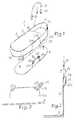
- a baby footmuff is shown in a Container for carrying babies is convertible like him is known for example from DE 40 02 426 C2. It any other container can also be used, which has the shape of a footmuff and in a pushchair or in another child transport facility of the type specified at the beginning without a floor reinforcement plate can be used, e.g. B. also a rectangular one or box-shaped container, the head part of which is not or is otherwise changeable.
- This footmuff 1 points a circumferential in the position of use shown Wall formed from the side walls 3a, 3b and the end walls (Head and foot walls) 5a, 5b, on.
- the front wall 5a can also be shown via not shown Detachable or shortened elements in the edge area for one Spread out the second position of use, but this is not mandatory necessary is.
- the head wall part 5a comprises the head part wall 7, while the side wall parts 3a and 3b, who join the lower part 6 together with the Limit foot section 5b.
- the closed one thus formed Wall can be fixed to the bottom part 4 or else e.g. B. by means of a zipper or surface zipper element be made separable from it.
- This upper part 2 can also be made removable or foldable what purpose in the side area z. B. zippers or Surface zipper elements are to be provided.
- the top 2 can also together with the side wall parts 3a and 3b and the foot wall part 5b executed bowl-shaped be and detachably attached to the lower part. All of these statements are in the cited patent described in more detail.
- the design of the angle stiffening device is essential to the invention, the one in this example Floor reinforcement plate 8, only from the bottom can be attached to the footmuff 1.
- This floor reinforcement plate 8 at least on the long sides, approximately in the area the transverse axis of focus of the footmuff with inside baby or toddler, standing up Has wall stiffening elements 9a and 9b, the relative are resistant to bending and torsion and a little less Have height than the side wall parts 3a, 3b and usually under the upper edge of the side wall parts 3a, 3b end or protrude from openings above.
- This torsion-resistant wall stiffening elements designed as a standing wall 9a, 9b are essentially rectangular from the level of the floor reinforcement plate 8 above and are so firmly attached that their position cannot be changed.
- the wall stiffening elements 9a and 9b are pocket-shaped from below Recordings 38 in the side wall parts 3a and 3b of the Footmuff 1 inserted and end in the upper edge area.
- This edge area of the side wall parts 3a, 3b of the footmuff has slot-shaped openings 37a and 37b, from which either in extension of the top of the Wall stiffening elements 9a, 9b projecting lock systems protrude or sunk below the opening 37a, 37b end up.
- the lock systems are shown in the Embodiment through to the wall stiffening elements 9a and 9b attached triangular Castle wall 10a and 10b formed, as shown in Figure 2 is.
- the front an opening 11 in the wall 10a or 10b has, the lock counter-element 19 of a handle or a shoulder strap 18 can be inserted.
- the plug lock element consists of a carrier part 12, such as Figure 2 shows that a transverse slot for Includes a loop 14 of the shoulder strap 18.
- On the carrier 12 is a resilient in a known manner Lock wedge 13 attached in the direction of the carrier 12th can be pressed when it is in the opening 39 of the lock part 10a, 10b inserted on the wall stiffening elements 9a, 9b becomes.
- the spring lock wedge 13 engages with a click with the top edge under the top edge of the opening 11, so that the riser 8 firmly on the fastener 9a, 9b is attached. It is to solve required again on the spring-loaded lock wedge 13 and push it so far into the opening 39 move that the locking edge is inside the opening 39 is located so that the lock wedge 13 of the lock part 19 can be pulled out of the opening 39.
- the pressure surface of the lock wedge 13 is accessible either through the opening 37a, 37b or from the outside by pressure on the textile fabric or through a recess in the textile Wall fabric of the side wall part in the area of Breakthrough 11.
- a special feature is that when using the footmuff 1 as a baby carrier or as a container for carrying a baby via the attachment the risers 18, which are provided on both sides are, the floor reinforcement plate 8 automatically to this is attached with.
- special fasteners e.g. B. push button connections, on the bottom of the bottom 4 or on the inside of the pocket-shaped Opening 3 may be provided with the corresponding Counter elements on the floor reinforcement plate 8 or on the wall stiffening elements 9a, 9b are connectable.
- the floor reinforcement plate 8 with the wall reinforcement elements 9a, 9b and the lock case Conveniently made of plastic and in one piece educated.
- FIG 3 is a variant of the wall stiffening element 9a and 9b shown. As can be seen from that bevels in the upper corner areas for easier Introduced into the pocket 38 of the side wall part. Furthermore, parallel to this are also diagonally opposite the floor reinforcement plate 8 elongated holes 15a and 15b for receiving a loop 16 made of belt material provided, at the ends of buckle elements 17 attached are, as is common with all seat belts is.
- the invention is not related to a special lock system tied for seat belts.
- angles of inclination also show that this a V-shaped extension is given, so that the corresponding attached handle or shoulder strap 18 with his Counter-lock element 19 have a slight arch shape can, especially if it is a relatively stiff bracket is trained.
- FIG. 4 there is a floor reinforcement plate 8 shown that not only laterally Wall stiffening elements 9a and 9b, but also in the head wall part another upstanding wall stiffening element 21 and in the foot wall part a wall stiffening element 22 has. These are fitted into the arch parts. But you can also with appropriate execution of the footmuff be square. The width and the Strength and a profile are the desired ones Gain dependent.
- a rotating, trough-shaped edge 35 to improve stability the floor reinforcement plate 8 is provided is.
- This is practically an interrupted tub shape realized on - in the same way as on the basis of Figure 1 described - the footmuff is attachable.
- this part can be made of plastic or a pressable Molding material, e.g. B. pressed cardboard.
- FIG. 5 shows a further variant of a floor reinforcement plate 8 with lamellar, finger-like wall stiffening elements 20a and 20b shown, which also a sheet-like wall stiffening element 21 in the head wall part having.
- This presentation is intended to show that individual web-shaped or tongue-shaped wall stiffening elements 20a and 20b, placed at appropriate locations, serve the same purpose, namely to prevent in the case of a weight resting on it, transverse on the carrier bag this can collapse.
- the desired effect can be enhanced by from above onto the individual slats or onto the wall-shaped wall stiffening elements 9a, 9b according to figures 1 and 4 a transverse reinforcement element 36 is plugged on becomes. Accordingly, this points on the sides, for example Elongated holes with which the cross reinforcement element 36 on connection-adapted wall stiffening elements 9a, 9b or slats 20a, 20b or on the above approaches attachable to the wall stiffening elements 9a and 9b is. As a result, the upper part 2 can also be longitudinally applied parts to no contraction of the side walls to lead. This creates the desired stability effect reinforced.
- a cross reinforcement element is not mandatory.
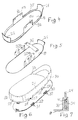
- FIG. This consists in that in the side wall 3a, 3b or in the end wall 5b (the same also applies to the end wall 21 already in the head area) a strip-shaped wall stiffening element 24 or 23 has moved in; for example be a very stable cardboard.
- This wall stiffening element shows protrusions 25 below and 26 on to the wall stiffening element 24 and 23 respectively the bottom reinforcement plate 8, which can be attached from below to be able to.
- These are in the exemplary embodiment running congruently in the floor reinforcement plate 8 Elongated holes 29 and 30 with transverse spring-loaded Bars 31 and 32, which can be pulled forward, so that the above approaches 25 and 26 in the Elongated holes 29 and 30 can be inserted.
- FIG. 7 Another type of attachment can be seen in Figure 7. So can on the floor reinforcement plate 8 also upwards standing U-shaped receptacles from walls 33 and 34 or webs can be provided, which in pocket-shaped openings of the side walls 3a and 3b of the footmuff from below intervene and then the wall stiffening elements 24 or 33 can be pressed in from above. A prominent one Can snap on the wall 34 of the U-shaped receptacle thereby in a correspondingly placed recess 41 of the Snap the wall stiffening element 24 into place.
- This connection can pull on the side wall 3a, 3b can be released after removing the handle, by taking advantage of the inherent elasticity of the wall 34
- additional fasteners such as snap fasteners or surface zip connections, for fixing the footmuff 1 to the floor reinforcement plate 8 to be provided.
- FIGS. 8 and 9 show a floor reinforcement plate according to the invention shown, which consists of plastic. To reduce weight are both in the wall-shaped wall stiffening elements 9a and 21 openings 42 provided as well as in the floor reinforcement plate 8 even such cutouts 43. Through this structure will also have high rigidity at the same time Weight reduction guaranteed.
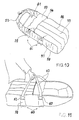
- the container comprises one another example, a bottom portion 51, which in a Representation almost completely of a cover section 52 is covered.
- the cover section 52 instructs its end section facing the head region of the container a padded cap 53.
- the padded Cap 53 is in an opened position via buttons 54 held. It is also possible to use the padded one Fasten flap 53 so that one of a hood section 55 surrounding head area of the container is covered even further.
- the cover section 52 is with Quilting seams 56 provided.
- a connecting device in particular in the form of a zipper 58, intended. After opening the connection device the cover section 52 can be folded down and in particular via the buttons 54 can be locked in a position in which through the cover section 52 an extended leg receiving area is available.
- each other spaced tabs 59 formed on the respective Longitudinal side section 57 are sewn on.
- an angle stiffening element 60 is held. This is preferably made of plastic (injection molded part).
- the tab 59 is in the upper one Area not shown in the drawing. Instead is the course of the seam with which the tab 59 on the portable container is attached, in dash-dotted lines Line shown.
- each angle stiffening element 60 has a snap element 61 on.
- This snap element 61 is in one piece formed and forms the angle stiffening element 60 a resilient with a counter-closure element 62 one Handle 63 lockable lock part.
- the snap elements 61 and the counter lock 62 added in the respective tabs 59 to an appealing To create appearance. Beyond that in such a configuration, the sometimes sharp-edged and hard fastener from a soft Fabric cover, which is formed by the tab 59, covered.
- the ends of two are opposite Webs of the longitudinal side sections 57 stiffening angle stiffening elements through the over the handles 63 transferred holding force towards each other pulled when the container is lifted. Because of your Stiffness is prevented, however, by this Traction the longitudinal side portions 57 through the bottom portion 51 and that surrounding the bottom section 51 Wall-formed picture reduced for the toddler becomes. Those resting on the underside of the bottom section 51 Legs of the angle stiffening elements 60 can to increase the stiffness of the portable container be held in pockets overall. These bags can for easier removal of the angular stiffening elements 60 closable from the tabs 59 by a Velcro fastener his. In the present case, the angle stiffening elements 60 but connected to each other.
- an angular stiffening element has 60 a in the longitudinal direction of the at the bottom portion 5 adjacent legs a recess 64 on.
- a web 65 of the opposite Angle stiffening element added.
- This Angular stiffening element is only with its on the Bottom portion 51 shown adjacent legs.
- the web 65 has two opposing springs 66 on the in the recess 64 formed grooves 67 shown in FIG. 13 intervention. The web 65 is thus in the recess 64 in Longitudinal direction of the web resting on the bottom section kept slidable.
- the snap element 61 has two identically designed Wing 68 on by a in the longitudinal direction of the Longitudinal side section stiffening leg of the angle stiffening element 60 formed throat 69 from each other are spaced. This allows the wings 18 to be elastic are moved towards each other to counterpart 62 the handle 63 to snap with the snap element 61.
- the angular stiffening element shown completely in FIGS. 12 and 13 shows two in the longitudinal direction of the Angle stiffening element 60 extending stiffening ribs 70 on.
- the stiffening ribs 70 are parallel arranged to each other.
- the strength of the stiffening ribs 70 continuously takes off from the ends of each Thighs up to a knee 71 on which the two legs are connected to each other.
- the configuration of the angle stiffening device 60 can be seen in particular in Figure 13, the one Longitudinal section through the angle stiffening element shown in Figure 12 60 shows.
- the angular stiffening element 60 essentially from one angular base part, the base part the two legs formed at right angles to each other has, whose outer surfaces are parallel to each other run.
- the stiffening ribs 70 rise in each case in a direction transverse to the central longitudinal axis to the edge of the Leg.
- the stiffening ribs In the area of the knee 71, the stiffening ribs have 70 a thickening 72. On the outside surface the thickening 72 is itself at the lowest point Standing surface 73 extending parallel to the horizontal educated.
- Admission for the toddler will be the opposite Stiffening elements 60 initially in the longitudinal direction the leg of the respective abutting the bottom section 51 Angular stiffening elements 60 pushed into one another.
- the springs formed on the web 65 66 brought into engagement in the grooves 67 of the recess 64. This results in a torsion and bending resistant Connection of the opposite angle stiffening elements 60.
- the two become themselves opposite angle stiffening elements 60 formed U-shaped stiffening element with the longitudinal side sections 57 stiffening thighs from the bottom down pushed into the tabs 59 above.
- the handles 63 by locking the counter-closure elements 62 on the snap elements 61 with the angle stiffening elements 60 connected.
- the Thickness of the thickening 72 indicates the distance between the bottom and the bottom portion 51.
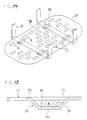
- FIG. 14 shows a perspective view of an exemplary embodiment a floor stiffener 74 which a stiffening plate 75.
- the stiffening plate 75 has two in the front area opposite one another in the transverse direction arranged recordings 76 on. In the same Ways are in the rear area of the stiffening plate 75 receptacles 76 arranged at the same height are formed.
- the recesses 77 extend in the longitudinal direction the stiffening plate 75, i.e. the length of the Recesses 77 in the longitudinal direction of the stiffening plate 75 is larger than its width. Lie lengthways the recesses 77 in a row. Are in the transverse direction however, adjacent recesses 77 are offset from one another arranged to provide even flexural rigidity To effect stiffening plate 75 in the longitudinal direction.
- FIG 15 is an enlarged sectional view along the line VI-VI shown in Figure 14.
- the recording 76 has a transverse to the longitudinal extension of the stiffening plate 75 extending insertion opening 78, the has essentially a trapezoidal cross-sectional area and is surrounded by a wall 79.
- the wall 79 has a substantially parallel to the stiffening plate 75 extending wall segment 79a.
- the cross-sectional area of the insertion opening 78 is such designed that a in the receptacle 76 through the Insert opening 78 inserted leg of an angle stiffening element 60 securely held in the receptacle 76 is.
- the cross-sectional area of the insertion opening 78 however chosen such that the stiffening elements 60 in the transverse direction of the stiffening plate 75 in the receptacle 76 is displaceable.
- the receptacle 76 opens to the inner surface of the stiffening plate 75 through an opening 80.
- the receptacle 76 opens to the inner surface of the stiffening plate 75 through an opening 80.
- the parallel to that inserted in the insertion opening Leg of the angle stiffening element 60 extending Boundary surfaces of the opening 80 as an extension the trapezoidal inner side surfaces the wall 79 is formed.
- angle stiffening elements 60 are provided, whose extending parallel to the stiffening plate 75 Legs can be pushed into each other, as above with reference to Figures 12 and 13 in more detail has been explained. This makes it possible to change the width between the vertical legs of the angle stiffening elements 60 variable and adjust to the dimensions to adapt the respective flexible bag body.
- the invention is not based on the above Embodiment limited.
- two angle stiffening elements as one piece, To form a U-shaped stiffening element, its middle leg to the width of the bottom section is adjusted.
- alternative configurations to the tongue and groove connection described between two opposing angle stiffening elements Especially in manufacturing the plastic angle bracing elements can it may be desirable to have the opposite angular stiffening elements through a large-area connection to connect positively to each other in such a way that the two angle stiffening elements in the longitudinal direction of the legs adjoining the bottom section are adjustable with one another are connected.
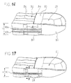
- FIGS. 16 and 17 of a portable container depicts what's going on especially for realizing the present invention is suitable.
- the embodiment shown in Figures 16 and 17 of a portable container according to the invention corresponds essentially to that in FIGS. 10 and 11 embodiment shown. Accordingly the same components are provided with the same reference numerals.
- each Longitudinal side wall sections are height adjustment devices 90 , which in the present case is essentially a extending parallel to the bottom portion Zipper are formed.
- the two halves 90a, 90b of the zipper 90 spaced apart.
- the Halves of the zipper 90 are with the outer surfaces the tabs 59 and the longitudinal side wall sections 57 sewn.
- the height adjustment device shown in FIGS. 16 and 17 extends in the longitudinal direction of the longitudinal side wall sections 57 from the foot end of the portable container up to the hood portion 55.
- the Zipper 90a, 90b ends at the point where the present embodiment by the zipper 90 formed connection between the longitudinal side wall sections 57 and the cover section 52 ends.
- Figure 17 is the tote bag shown in Figure 16 shown in a state of reduced height.
- the zipper 90 is closed, so that a height h of the portable container gives the opposite the height H according to FIG. 16 by the distance between the two Zipper halves 90a, 90b is reduced.
- height adjustment device is preferably designed such that the Height of the longitudinal side wall sections 57 by 20% to 35% can be reduced by actuating the height adjustment device 59 is.
- FIG. 18 shows a longitudinal sectional view along the Line IX-IX as shown in Figure 17.
- the longitudinal side wall section extends in the direction 57 from the bottom portion 51, the outer surface of the longitudinal side wall section 57 in the area of a Fold 57a through the joined halves of the Zipper 90a, 90b are formed.
- the closed prevents Zipper 90 that extends the longitudinal side wall section to its full height.
- the fold 57a extends in a longitudinal direction over both tabs 59, are the tabs 59 at full height through the fold 57a relocated. This prevents the Portable container according to the invention at a reduced height is used as a carrier bag. This is desirable if the container with reduced height is not a baby carrier should be used. Serves in this function the container as a footmuff.
- Figure 18 also shows that the folded extension part 57a protrudes on the inside.
- the zipper is attached on the inside, protrudes the fold 57a in the interior. If the zipper becomes 90 opened, the height is extended by the pull-out height of the extension part or the fold 57a.
- the wall stiffening element of the angle stiffening element 60 can be inserted below and the horizontal leg into the opening 92 in the bottom part 51.
- the opening 92 is formed by the textile layers 93 and 94.
- the floor reinforcement plate 74 is inserted from above drawn in, with their bridge elements 79, the one Have feet, used in openings in the floor are so that when inserting the horizontal leg a closed network is created. On the floor reinforcement plate an edition 91 is placed.
- the formation of the height adjustment device be modified.
- several strips of one type of zipper to be arranged one above the other on the longitudinal side wall sections.
- the high of Longitudinal side wall sections 57 can be set as desired be, if at least instead of a zipper partially extending over the longitudinal side wall sections Cord provided in eyelets or tabs is. By shortening the cord, the height of the longitudinal side wall sections can be reduced 57 can be changed as required.
- Alternatively can also hook on the longitudinal side wall sections be formed, the eyelets assigned in the hook are attachable.
- it is possible to change the amount of To reduce longitudinal side wall sections by buttons those associated with buttonholes or small tabs can be brought.
- a particularly easy to operate Height adjustment device is by Velcro formed on the outside of the longitudinal side wall sections 57 are arranged or on the inside can be provided. The closure designs are known as such.
- the connecting elements on the inside or outside of the side wall be provided.
Landscapes
- Purses, Travelling Bags, Baskets, Or Suitcases (AREA)
- Packages (AREA)
- Details Of Rigid Or Semi-Rigid Containers (AREA)
- Massaging Devices (AREA)
- Acyclic And Carbocyclic Compounds In Medicinal Compositions (AREA)
- Toys (AREA)
- Carriages For Children, Sleds, And Other Hand-Operated Vehicles (AREA)
- Radiation-Therapy Devices (AREA)
Description
- FIG 1
- in vereinfachter perspektivischer Explosionsdarstellung einen Fußsack mit darunter befindlicher erfindungsgemäß ausgeführter Verstärkungsplatte und darüber befindlichem bügelförmigen Tragegurt;
- FIG 2
- ein mögliches Steckschloßsystem zur Ankopplung des Tragegurtes;
- FIG 3
- eine andere Anordnung der Befestigung eines Tragegurtes an einem Wandversteifungselement;
- FIG 4
- eine weitere wannenförmige Ausführungsform der Bodenversteifungsplatte mit Wandversteifungselementen gemäß der Erfindung;
- FIG 5
- eine andere Ausführungsform mit einem Querversteifungsteil oberhalb lamellenartiger Wandversteifungselemente;
- FIG 6
- eine Explosionszeichnung einer erfindungsgernäßen Ausführung eines Fußsackes mit darunter befindlicher Bodenversteifungsplatte;
- FIG 7
- eine weitere Ausführung einer Verbindung zwischen Bodenversteifungsplatte und Verstärkungselement gemäß FIG 6;
- FIG 8
- eine Seitenansicht einer Bodenversteifungsplatte mit Wandversteifungselementen an den Seiten und der Stirnseite des Kopfteils;
- FIG 9
- eine Unteransicht der Verstärkungsplatte gemäß FIG 8;
- FIG 10
- eine perspektivische Ansicht eines Ausführungsbeispiels eines erfindungsgemäßen Behältnisses mit abgenommenen Tragegriffen,
- FIG 11
- eine perspektivische Ansicht des in FIG 10 dargestellten Behältnisses in einer Tragestellung,
- Fig 12
- eine perspektivische Ansicht eines Ausführungsbeispiels eines Winkelversteifungselementes mit einem Teilstück eines korrespondierenden Winkelversteifungselementes zur Bildung eines U-förmigen Versteifungselementes,
- FIG 13
- einen Längsschnitt entlang der Mittellängsachse des in FIG 12 vollständig gezeigten Winkelversteifungselementes,
- FIG 14
- eine perspektivische Ansicht eines Ausführungsbeispiels einer mit einer Winkelversteifungseinrichtung verbundenen Bodenversteifungseinrichtung,
- FIG 15
- eine vergrößerte Schnittansicht entlang der Linie VI-VI gemäß FIG 14,
- FIG 16
- eine perspektivische Ansicht eines weiteren Ausführungsbeispiels eines mit einer Winkelversteifungseinrichtung zu versteifenden tragbaren Behältnisses;
- FIG 17
- eine perspektivische Ansicht des in FIG 16 dargestellten tragbaren Behältnisses mit verringerter Höhe, und
- FIG 18
- eine vergrößerte Schnittansicht des Längs-Seitenwandabschnittes entlang der Linie III-III gemäß FIG 17.
Claims (44)
- Tragbares Behältnis (1) für ein Kleinkind, mitdadurch gekennzeichnet,einem Bodenteil (4, 51),einer diesen zumindest teilweise umgebenden Wandung (3a, 3b, 5a, 5b; 57, 59) aus an den Längsseiten vorgesehenen Seitenwandteilen (3a, 3b, 57) und stirnseitigen Fuß- (56) und Kopfwandteilen (5a, 55),einer Trageeinrichtung (18, 19; 63),Winkelversteifungseinrichtungen, die einen quer zum Boden verlaufenden Abschnitt und einen weiteren, im wesentlichen senkrecht nach oben stehenden, ein Seitenwandteil stützenden Abschnitt aufweisen,daß die Winkelversteifungseinrichtung (24, 60) mindestens ein im wesentlichen senkrecht hochstehendes Wandversteifungselement (9a, 9b; 20a, 20b; 24; 60) zur winkelstabilen Verbindung zumindest eines Abschnittes der Wandung (3a, 3b, 5a, 5b; 57, 59) mit dem Bodenteil (4, 51) ist,welche Winkelversteifungseinrichtung (24, 60) mindestens im Bereich des Bodenteils (4, 51) mit mindestens einem weiteren paarig hierzu angeordneten Element lösbar verbunden ist oder an einem Bodenversteifungselement (8) im oder am Bodenteil (4) mittels einer Verbindungsanordnung (78, 79, 79a) lösbar fixiert ist oder mit dem Bodenversteifungselement (8, 74) einteilig ausgeformt ist unddaß die Seiten-, Fuß- und Kopfwandteile von den Winkelversteifungseinrichtungen und dem Bodenversteifungselement trennbar ausgebildet sind.
- Tragbares Behältnis nach Anspruch 1 gekennzeichnet durch eine Höheneinstelleinrichtung (90, 90a, 90b) für die Veränderung der Höhe der Wandeng (3a, 3b, 5a, 5b; 57, 59) derart, daß die Wandung (3a, 3b, 5a, 5b; 57, 59) aus einer unteren in eine obere Gebrauchshöhe verstellbar ist, in welchen das Kleinkind jeweils mindestens seitlich geschützt ist.
- Tragbares Behältnis nach Anspruch 1 oder 2, dadurch gekennzeichnet, daß die Wandversteifungselemente (9a, 9b; 20a, 20b; 60) der gegenüberliegenden Seitenwandteile (3a, 3b; 57) im Bereich des Bodenteils (4) einstellbar miteinander verbunden sind und/oder daß sie am Bodenversteifungselement (8) in eine bestimmte seitliche Zuordnung verbringbar fixiert sind.
- Tragbares Behältnis nach Anspruch 3, dadurch gekennzeichnet, daß die Winkelversteifungseinrichtung aus mindestens einem Paar Versteifungswinkeln (60) aus jeweils mindenstens einem Wandversteifungselement und mindestens über einen Teilbereich entlang des Bodens sich erstreckenden Schenkel besteht, wobei die Schenkel im Gleitverschiebeeingriff, insbesondere in Verbindung mit einer Gleitführungseinrichtung, miteinander verbunden sind.
- Tragbares Behältnis nach einem der vorhergehenden Ansprüche, dadurch gekennzeichnet, daß zumindest die Wandversteifungselemente biegesteifigkeitserhöhende Querschnittskonfigurationen (70, 72) aufweisen.
- Tragbares Behältnis nach Anspruch 5, dadurch gekennzeichnet, daß die biegesteifigkeitserhöhende Querschnittskonfiguration (70, 72) des Wandversteifungselementes Versteifungsrippen sind, die an der Innen- und/oder Außenseite, in Längsrichtung verlaufend, mindestens an einem der Schenkel vorgesehen sind.
- Tragbares Behältnis nach einem der vorhergehenden Ansprüche, dadurch gekennzeichnet, daß in Verlängerung und aus dem Bodenteil (4) vorstehend am Wandversteifungselement oder am Schenkel Stützfüße (73) als Auflager des tragbaren Behältnisses (1) gegenüber einem Untergrund vorgesehen sind.
- Tragbares Behältnis nach einem der vorhergehenden Ansprüche, dadurch gekennzeichnet, daß das Bodenversteifungselement (8) eine Bodenversteifungsplatte ist.
- Tragbares Behältnis nach Anspruch 8, dadurch gekennzeichnet, daß das Wandversteifungselement (24) mit einem Befestigungsansatz (25, 26) durch Durchbrüche (29, 30) im Randbereich der Bodenversteifungsplatte (8) hindurchsteckbar und mittels Befestigungselemente (31, 32) an der Unterseite der Bodenversteifungsplatte (8) hieran fixierbar ist.
- Tragbares Behältnis nach einem der vorhergehenden Ansprüche, dadurch gekennzeichnet, daß sowohl in den Seitenwandteilen (3a, 3b) als auch in den stirnseitigen Fußund/oder Kopfteilen (5a, 5b) Wandversteifungselemente (21, 22) von Winkelversteifungseinrichtungen vorgesehen sind.
- Tragbares Behältnis nach einem der vorhergehenden Ansprüche, dadurch gekennzeichnet, daß die Wandversteifungselemente (20a, 20b) zungen- bzw. stegförmig oder als Flächenelemente (9a, 9b, 24) über einen längeren Teilabschnitt der jeweiligen Wand verlaufend ausgebildet sind oder geschlossene oder unterbrochene oder rahmenförmige Wandteile bilden.
- Tragbares Behältnis nach einem der Ansprüche 8 bis 11, dadurch gekennzeichnet, daß die Bodenversteifungsplatte (8) einen umlaufenden nach oben vorstehenden Randteil zur Bildung einer flachen Wanne aufweist und daß in dem Rand Vorrichtungen (33, 34) zur Befestigung der Wandversteifungselemente (24), vorzugsweise Rastaufnahmen mit seitlichen Stützwänden, vorgesehen sind.
- Tragbares Behältnis nach einem der vorhergehenden Ansprüche, dadurch gekennzeichnet, daß die oberen freien Enden eines in den Seitenwandteilen (3a, 3b, 57) angeordneten Wandversteifungselementenpaar mittels lösbarer Querversteifungselemente (36) verbunden sind oder an den Seitenwandteilen im oberen Randbereich Vorrichtungen zur lösbaren Fixierung mindestens eines Querversteifungselementes (36) vorgesehen sind.
- Tragbares Behältnis nach einem der Ansprüche 1 bis 8 oder 11, dadurch gekennzeichnet, daß die Verbindungsanordnung zumindest an der dem tragbaren Behältnis abgewandten Außenseite der Bodenversteifungsplatte (8) ausgebildete Aufnahmen (75) umfaßt, in die die Winkelversteifungselemente (60) mit ihren horizontal sich erstreckenden Schenkeln einschiebbar sind.
- Tragbares Behältnis nach Anspruch 14, dadurch gekennzeichnet, daß die Aufnahmen (75) an der Bodenversteifungsplatte (8) an der Unterseite oder der Oberseite angebrachte, mit den darunterliegenden oder den sich anschließenden Flächen (80) korrespondierende Brückenführungselemente (79, 79a) sind, deren Durchtrittsöffnungen (78) winklig zur Außenkante verlaufen.
- Tragbares Behältnis nach Anspruch 15, dadurch gekennzeichnet , daß die Brückenführungselemente (79, 79a) zur Innenseite der Bodenversteifungsplatte sich öffnen und eine sich nach außen verjüngende Querschnittsform aufweisen und so ausgebildet sind, daß sie beim Stapeln der Bodenversteifungsplatten (8) ineinandergreifen.
- Tragbares Behältnis nach Anspruch 8, dadurch gekennzeichnet, daß die Bodenversteifungsplatte (8) eine in Längsrichtung und/oder Querrichtung (43, 77) biegesteifigkeitserhöhend wirkende Querschnittskonfiguration oder Verrippung aufweist.
- Tragbares Behältnis nach einem der Ansprüche 7 bis 17, dadurch gekennzeichnet, daß die Bodenversteifungsplatte (8) aus Segmenten oder Streifenelementen besteht, die untereinander in Schiebefügeverbindung angeordnet sind oder auf einem Rahmen verschiebbar und/oder gegeneinander verstellbar angeordnet sind und daß durch gegenseitige Verschiebung der Segmente oder Streifen bzw. Verstellung eine fiktiv größere Fläche einstellbar ist.
- Tragbares Behältnis nach einem der vorhergehenden Ansprüche, dadurch gekennzeichnet, daß quer zur Längsachse des Bodenversteifungselementes (8) verlaufend an diesem und/oder außen an den Seitenwänden Trageeinrichtungen (18, 19; 63) in Form von Tragegurten bzw. Tragebügeln vorgesehen sind, die an den Seitenwandteilen (5a, 5b) und/oder an den Bodenversteifungselementen (8) fixiert sind.
- Tragbares Behältnis nach einem der Ansprüche 1 bis 18, dadurch gekennzeichnet, daß die Trageeinrichtungen (18, 19; 63) jeweils an den oberen Enden zweier beabstandeter Wandverstärkungselemente (20a, 20b; 60) in einem Seitenwandteil (3, 3b; 57), an den Enden zweier paarweise in den Seitenwandteilen vorgesehenen Wandversteifungselementen (60) oder an entsprechenden beabstandeten Befestigungseinrichtungen (10a, 10b, 39) an einem flächenförmigen Wandversteifungselement (9a, 9b, 24) befestigt sind.
- Tragbares Behältnis nach Anspruch 20, dadurch gekennzeichnet, daß die Enden und/oder die Befestigungselemente der Trageeinrichtung (18, 63) integrale, lösbar ineinanderfügbare Schnappverschlußelemente (19, 62) aufweisen.
- Tragbares Behältnis nach einem der vorhergehenden Ansprüche, dadurch gekennzeichnet, daß die Wandversteifungselemente (9a, 9b; 20a, 20b) in taschenförmige Öffnungen (38) in den Seitenwänden (3a, 3b) von der Unterseite her einsetzbar sind und innerhalb der Seitenwände (3a, 3b) enden oder aus diesen aus der Oberseite mindestens teilweise durch Öffnungen hervortreten oder daß die Wandversteifungselemente in mindestens den Längs-Seitenwandteilen (57) vorgesehenen Laschen (59) aufgenommen sind.
- Tragbares Behältnis nach Anspruch 22, dadurch gekennzeichnet, daß sich die Höheneinstelleinrichtung über die Laschen (59) erstreckt.
- Tragbares Behältnis nach Anspruch 22 oder 23, dadurch gekennzeichnet, daß bei versenkter Anordnung der Wandversteifungselemente in den Oberseiten der Seitenwandteile (3a, 3b) Öffnungen (37a, 37b) für das Einsetzen der Enden (19) eines Tragegurtes (18), Bügels oder Tragegriffes vorgesehen sind und bei vorstehenden Teilen der Wandversteifungselemente aus der Oberseite der Seitenwandteile oder bei in Laschen geführten Wandversteifungselementen die Enden eines Tragegurtes (18), Bügels oder Tragegriffes jeweils an zwei beabstandeten Wandversteifungselementen (20a, 20b; 60) in bzw. an demselben Seitenwandteil befestigt sind.
- Tragbares Behältnis nach einem der Ansprüche 22 bis 24, dadurch gekennzeichnet, daß am oberen Bereich der Wandversteifungselemente (9a, 9b) Steckschloßsysteme (10a, 11, 16, 17) vorgesehen oder hieran befestigt sind, die mit Gegensteckschloßsystemen (12, 13, 14; 17, 19) an dem Tragebügel oder dem flexiblen Tragegurt (18) lösbar verbunden sind.
- Tragbares Behältnis nach Anspruch 8, dadurch gekennzeichnet, daß die Bodenversteifungsplatte (8) mit den Wandversteifungselementen (9a, 9b; 20a, 20b) einteilig aus Kunststoff, Preßpappe oder einem anderen gießoder preßbaren Werkstoff ausgeformt ist.
- Tragbares Behältnis nach Anspruch 1, 8 oder 26, dadurch gekennzeichnet, daß die Bodenversteifungsplatte (8) und/oder die wandförmigen Wandversteifungselemente Öffnungen (42, 43), Durchbrüche und/oder Freischnitte aufweisen, in sich aber verbiegesteif sind.
- Tragbares Behältnis nach einem der Ansprüche 21 bis 27, dadurch gekennzeichnet, daß an dem oder an den Wandversteifungselementen (9a, 9b; 20a, 20b) seitlich beabstandet zwei Steckschloßkammern (39) angebracht sind, in die federbelastete, schwenkbewegliche Schloßzungen (13) eines Schloßsystems an der Trageeinrichtung einführbar sind, wobei jeweils eine Seitenwand (9a) und eine hieran befestigte in Schließrichtung keilförmig verlaufende, die Kammeröffnung begrenzende Wand (10a), die einen Durchbruch (11) aufweist, in den ein Rastansatz (13) an der Schloßzunge im eingeschobenen Zustand lösbar einrastet, die Steckschloßkammer (39) bilden.
- Tragbares Behältnis nach einem der Ansprüche 21 bis 27, dadurch gekennzeichnet, daß ein Mutterteil (17) eines Steckschlosses mittels eines Gurtes (16) an dem Wandversteifungselement (9a, 9b), vorzugsweise durch eine Öse (15a, 15b) gezogen, angebracht ist und daß in die Öffnungen (37a, 37b) der Mutterteile (17) des Schloßsystems die Stecklaschen bzw. Schloßzungen (19) des Tragebügels bzw. Tragegurtes (18) einsteckbar sind.
- Tragbares Behältnis nach einem der Ansprüche 21 bis 29, dadurch gekennzeichnet, daß Langlöcher (15a, 15b) zur Aufnahme der Befestigungsgurtschlaufen (16) des Gurtes vorgesehen sind bzw. fest integrierte Schloßöffnungen (39) derart angeordnet sind, daß die Tragegurtenden V-förmig oder parallel zur Wandversteifungsplatte (8) verlaufen.
- Tragbares Behältnis nach einem der vorhergehenden Ansprüche, dadurch gekennzeichnet, daß mindestes im äußeren Randbereich der Bodenverteifungsplatte (8) und/oder mindestens an den Außenseiten der Wandversteifungselemente (9a, 9b, 24, 60) Befestigungsmittel, wie Druckknöpfe, Flächenreißverschlußelemente, Langlöcher oder Knebel für Langloch-Knebelverschlüsse oder dergleichen, angebracht sind und daß die Gegenelemente an der Unterseite oder an der Innenseite einer taschenförmigen Aufnahme in dem Bodenteil und/oder in den Seitenwänden des tragbaren Behältnisses zur Fixierung der Wandungen und des Bodens an den Bodenversteifungs- und Wandversteifungsplatte vorgesehen sind.
- Tragbares Behältnis nach Anspruch 31, dadurch gekennzeichnet, daß die taschenförmigen Öffnungen (38) zur Aufnahme der Wandversteifungselemente (9a, 9b; 20a, 20b) so ausgebildet sind, daß sie an Flächenreißverschlußelementen im unteren Bereich der Wandversteifungselemente (9a, 9b; 20a, 20b) selbsthaftend andrückbar sind oder mit Gegenflächenreißverschlußelementen versehen sind, um diese Verbindung mindestens an der Außenseite der Wandversteifungselemente (9a, 9b; 20a, 20b) herzustellen.
- Tragbares Behältnis nach einem der vorhergehenden Ansprüche, dadurch gekennzeichnet, daß die Wandung (3a, 3b; 5a, 5b; 57, 59) aus einem textilen oder folienartigen Stoff besteht, gepolstert, wattiert oder unwattiert ist, und daß in diesen Aufnahmen (38) oder an diesen die Laschen (59) vorgesehen sind, in die die Wandversteifungselemente (9a, 9b; 24, 60) von unten einführbar sind.
- Tragbares Behältnis nach einem der Ansprüche 20 bis 33, dadurch gekennzeichnet, daß die benachbarten stegförmigen Wandversteifungselemente (20a, 20b, 60) in einem Seitenwandteil (3a, 3b; 57) an ihren oberen Enden über einen Längsversteifungssteg miteinander gekoppelt sind.
- Tragbares Behältnis nach einem der vorhergehenden Ansprüche, dadurch gekennzeichnet, daß die Wandversteifungselemente (9a, 9b; 20a, 20b; 24, 60) in ihrer Länge gegenüber dem Boden (4) veränderbar sind.
- Tragbares Behältnis nach Anspruch 35, dadurch g e k e n n z e ic h n e t , daß eine Verlängerung durch den aufgesetzten Längsversteifungssteg oder durch aufsetzbare Verlängerungselemente erfolgt.
- Tragbares Behältnis nach Anspruch 36, dadurch gekennzeichnet, daß die Verlängerungselemente oder die Längsversteifungsstege Schloßverbindungselemente aufweisen, die einerseits auf die Enden der Wandversteifungselemente aufrasten und andererseits Vorrichtungen für die Verbindung mit den Trageeinrichtungen (18, 19; 62, 63) aufweisen.
- Tragbares Behältnis nach Anspruch 33 in Verbindung mit einem der vorhergehenden Ansprüche, dadurch gekennzeichnet, daß mindestens die Längswandteile (57) zur Veränderung der Höhe faltbare Längsstreifen (90a, 90b) aufweisen, die gegeneinander überlappbar und mittels Befestigungseinrichtungen wieder lösbar miteinander verbindbar sind.
- Tragbares Behältnis nach Anspruch 38, dadurch gekennzeichnet, daß die Befestigungseinrichtungen Reißverschluß- (90), Flächenreißverschlußelemente, Druckknopf- oder Hakenverbinder sind.
- Tragbares Behältnis nach einem der vorhergehenden Ansprüche, dadurch gekennzeichnet, daß das Bodenversteifungselement (8) und die Winkelversteifungseinrichtung aus dem Behältnis (1) für die Nutzung desselben in mindestens einer zweiten Gebrauchsfunktion herausnehmbar ist und daß mindestens der nicht versteifte Wandteil (3a, 5a) gegenüber dem Bodenteil (4) ausbreitbar, auf den Bodenteil (4) faltbar oder in der Höhe verkürzbar ist.
- Tragbares Behältnis nach Anspruch 40, dadurch gekennzeichnet, daß das über die Behälteröffnung (2) im unteren Abschnitt der Seitenwandteile (3a, 3b) und verbunden mit dem Fußwandteil (55) ein den Körper des Kleinkindes schützend übergreifendes Oberteil vorgesehen ist und daß sich daran der restliche Teil des Bodenteiles (4) mit einem ausgebreiteten oder wannenförmigen Kopfteil (5a) mit umlaufender Wandung anschließt.
- Tragbares Behältnis nach Anspruch 40 oder 41, dadurch gekennzeichnet, daß es in einer ersten Gebrauchsfunktion mit eingesetztem Bodenversteifungselement (8) und Winkelversteifungselement mit ausgefahrener Höhenverstelleinrichtung und Tragegriffeinrichtung als Babytragetasche und/oder Sport- oder Kinderwagenaufsatz verwendbar ist und in der zweiten Gebrauchsfunktion als Fußsack für Schlitten, Sport-, Buggy- oder Kinderwagen oder dergl. verwendbar ist.
- Tragbares Behältnis nach einem der vorhergehenden Ansprüche, dadurch gekennzeichnet, daß es in einer dritten Gebrauchsfunktion mit in der Höhe verkürzter Wandung mit Trageeinrichtung als flache Babytragetasche verwendbar ist.
- Tragbares Behältnis nach einem der vorhergehenden Ansprüche, dadurch gekenzeichnet, daß das Behältnis in der Größe der Verwendung als Behältnis für Puppen angelegt ist und hierfür verwendet wird.
Applications Claiming Priority (10)
| Application Number | Priority Date | Filing Date | Title |
|---|---|---|---|
| DE29710695U | 1997-06-19 | ||
| DE29710695U DE29710695U1 (de) | 1997-06-19 | 1997-06-19 | Fußsack für Kindersportwagen |
| DE19725958A DE19725958C2 (de) | 1997-06-19 | 1997-06-19 | Fußsack für Kindersportwagen |
| DE19725958 | 1997-06-19 | ||
| DE19748902A DE19748902B4 (de) | 1997-06-19 | 1997-11-05 | Tragbares Behältnis für ein Kleinkind |
| DE19748902 | 1997-11-05 | ||
| DE29805030U | 1998-03-19 | ||
| DE29805029U DE29805029U1 (de) | 1997-06-19 | 1998-03-19 | Tragbares Behältnis für ein Kleinkind |
| DE29805030U DE29805030U1 (de) | 1997-06-19 | 1998-03-19 | Tragbares Behältnis für ein Kleinkind |
| DE29805029U | 1998-03-19 |
Publications (3)
| Publication Number | Publication Date |
|---|---|
| EP0885577A2 EP0885577A2 (de) | 1998-12-23 |
| EP0885577A3 EP0885577A3 (de) | 1999-12-22 |
| EP0885577B1 true EP0885577B1 (de) | 2001-09-12 |
Family
ID=27512581
Family Applications (1)
| Application Number | Title | Priority Date | Filing Date |
|---|---|---|---|
| EP98110874A Expired - Lifetime EP0885577B1 (de) | 1997-06-19 | 1998-06-15 | Tragbares Behältnis für ein Kleinkind |
Country Status (4)
| Country | Link |
|---|---|
| EP (1) | EP0885577B1 (de) |
| AT (1) | ATE205372T1 (de) |
| DE (6) | DE29710695U1 (de) |
| DK (1) | DK0885577T3 (de) |
Families Citing this family (10)
| Publication number | Priority date | Publication date | Assignee | Title |
|---|---|---|---|---|
| DE29710695U1 (de) * | 1997-06-19 | 1997-08-14 | Fleischmann, Michael, 96275 Marktzeuln | Fußsack für Kindersportwagen |
| DE20001474U1 (de) * | 2000-01-27 | 2000-05-04 | Britax-Teutonia Kinderwagenfabrik GmbH, 32120 Hiddenhausen | Sitz- und/oder Liegeeinsatz |
| DE20213664U1 (de) | 2002-09-02 | 2002-11-07 | Tillmann, Marc, 10629 Berlin | Zusammenlegbares, wannenförmiges Behältnis |
| DE102007016438B4 (de) * | 2006-04-07 | 2012-09-06 | Udo Beger | Tragbares Behältnis für ein Kleinkind |
| KR200450651Y1 (ko) * | 2009-11-27 | 2010-10-20 | 신고은 | 유아용 힙시트 |
| US9221487B2 (en) | 2013-04-30 | 2015-12-29 | Graco Children's Products Inc. | Convertible stroller seat |
| DK177978B1 (da) * | 2013-08-30 | 2015-02-09 | Nskebørn As | Simpel montering af kasse på stel |
| FR3010682B1 (fr) | 2013-09-13 | 2015-10-23 | Babyzen | Poussette pliable adaptable au transport des nouveau-nes |
| DE202015101084U1 (de) * | 2015-03-05 | 2015-07-27 | Michael Fleischmann | Babytragetasche |
| EP4703238A1 (de) * | 2024-09-02 | 2026-03-04 | Thule Sweden AB | Babybassinette |
Citations (1)
| Publication number | Priority date | Publication date | Assignee | Title |
|---|---|---|---|---|
| US4571760A (en) * | 1983-05-13 | 1986-02-25 | Kassai Kabushikikaisha | Carry-cot |
Family Cites Families (9)
| Publication number | Priority date | Publication date | Assignee | Title |
|---|---|---|---|---|
| GB687797A (en) * | 1950-10-11 | 1953-02-18 | Reuben Thomas Ewart White | Improvements in or relating to carrier bags |
| DE1580193A1 (de) | 1966-10-13 | 1970-07-09 | Peggy Muenchner Kinderwagenfab | Kinderwagen |
| DE7016416U (de) * | 1970-04-30 | 1970-08-06 | Rojahn Karl-Heinz | Transportables behaeltnis fuer saeuglinge und kleinkinder. |
| DE4002426A1 (de) * | 1990-01-27 | 1991-08-08 | Michael Fleischmann | Fusssack fuer kindersportwagen |
| JPH0427662A (ja) * | 1990-05-21 | 1992-01-30 | Aprica Kassai Inc | 乳幼児用マットに保護壁を形成するための芯材および乳幼児用マット |
| DE4305548C2 (de) * | 1993-02-24 | 1996-09-19 | Albert Wegner | Transportables Behältnis für Säuglinge und Kleinkinder |
| FR2706408B1 (fr) * | 1993-06-15 | 1995-08-25 | Monneret Jouets | Véhicule du type poussette. |
| DE9409440U1 (de) * | 1994-06-10 | 1994-08-04 | Beger, Udo, 84032 Landshut | Tragbares Behältnis für ein Kleinkind |
| DE29710695U1 (de) * | 1997-06-19 | 1997-08-14 | Fleischmann, Michael, 96275 Marktzeuln | Fußsack für Kindersportwagen |
-
1997
- 1997-06-19 DE DE29710695U patent/DE29710695U1/de not_active Expired - Lifetime
- 1997-06-19 DE DE19725958A patent/DE19725958C2/de not_active Expired - Fee Related
- 1997-11-05 DE DE19748902A patent/DE19748902B4/de not_active Expired - Fee Related
-
1998
- 1998-03-19 DE DE29805030U patent/DE29805030U1/de not_active Expired - Lifetime
- 1998-03-19 DE DE29805029U patent/DE29805029U1/de not_active Expired - Lifetime
- 1998-06-15 EP EP98110874A patent/EP0885577B1/de not_active Expired - Lifetime
- 1998-06-15 AT AT98110874T patent/ATE205372T1/de active
- 1998-06-15 DE DE59801428T patent/DE59801428D1/de not_active Expired - Lifetime
- 1998-06-15 DK DK98110874T patent/DK0885577T3/da active
Patent Citations (1)
| Publication number | Priority date | Publication date | Assignee | Title |
|---|---|---|---|---|
| US4571760A (en) * | 1983-05-13 | 1986-02-25 | Kassai Kabushikikaisha | Carry-cot |
Also Published As
| Publication number | Publication date |
|---|---|
| DE29805030U1 (de) | 1998-09-10 |
| DE19748902B4 (de) | 2008-05-21 |
| DE19725958C2 (de) | 1999-07-29 |
| DE19725958A1 (de) | 1998-12-24 |
| DE19748902A1 (de) | 1999-05-06 |
| EP0885577A3 (de) | 1999-12-22 |
| ATE205372T1 (de) | 2001-09-15 |
| DK0885577T3 (da) | 2001-11-19 |
| DE59801428D1 (de) | 2001-10-18 |
| DE29710695U1 (de) | 1997-08-14 |
| DE29805029U1 (de) | 1998-08-27 |
| EP0885577A2 (de) | 1998-12-23 |
Similar Documents
| Publication | Publication Date | Title |
|---|---|---|
| DE69709177T2 (de) | Umwandelbarer mehrzweckkinderlaufstall | |
| EP2148594B1 (de) | Tragevorrichtung | |
| EP0503231B1 (de) | Unterlage für ein Kleinkind | |
| EP1795424B1 (de) | Umwandelbarer Sitz-Liegeeinsatz für Kinder- oder Puppenwagen | |
| EP0885577B1 (de) | Tragbares Behältnis für ein Kleinkind | |
| DE3417409A1 (de) | Tragbares kinderbett | |
| DE10321517B4 (de) | Zusammenlegbares, wannenförmiges Behältnis | |
| DE4002426C2 (de) | ||
| DE4305548C2 (de) | Transportables Behältnis für Säuglinge und Kleinkinder | |
| EP0686365B1 (de) | Tragbares Behältnis für ein Kleinkind | |
| DE102007016438B4 (de) | Tragbares Behältnis für ein Kleinkind | |
| DE4026843A1 (de) | Vorrichtung zum transport von patienten | |
| EP1031490A1 (de) | Dreirädriger Schiebewagen für Kinder und/oder Puppen | |
| DE19818503C2 (de) | Multifunktionales Gestell | |
| DE29723592U1 (de) | Warmhaltesack | |
| DE8527126U1 (de) | Auf dem Rücken tragbare, quaderförmige Tasche | |
| EP2292110B1 (de) | Aufklappbarer Fußsack für einen Kinderwagen sowie Kinderwagen, enthaltend einen aufklappbaren Fußsack | |
| DE29715123U1 (de) | Tragbares Behältnis für Säuglinge und Kleinkinder | |
| DE10121731B4 (de) | Warmhaltesack für Kinder | |
| DE102024136479A1 (de) | Babytragetaschenabdeckung und babytragetasche mit der babytragetaschenabdeckung | |
| DE9000922U1 (de) | Fußsack für Kindersportwagen | |
| DE29509285U1 (de) | Zusammenklappbares Reisebett, insbesondere Kinderreisebett, o.dgl. | |
| DE29601617U1 (de) | Zusammenlegbare Krabbeldecke für Babys oder Kleinkinder | |
| DE202024002661U1 (de) | Herunterlegbare Babytrage | |
| DE202004010986U1 (de) | Tragbares Behältnis für ein Kleinkind |
Legal Events
| Date | Code | Title | Description |
|---|---|---|---|
| PUAI | Public reference made under article 153(3) epc to a published international application that has entered the european phase |
Free format text: ORIGINAL CODE: 0009012 |
|
| AK | Designated contracting states |
Kind code of ref document: A2 Designated state(s): AT CH DE DK LI NL SE |
|
| AX | Request for extension of the european patent |
Free format text: AL;LT;LV;MK;RO;SI |
|
| RAP1 | Party data changed (applicant data changed or rights of an application transferred) |
Owner name: FLEISCHMANN, MICHAEL Owner name: BEGER, UDO |
|
| K1C1 | Correction of patent application (title page) published |
Effective date: 19981223 |
|
| PUAL | Search report despatched |
Free format text: ORIGINAL CODE: 0009013 |
|
| AK | Designated contracting states |
Kind code of ref document: A3 Designated state(s): AT BE CH CY DE DK ES FI FR GB GR IE IT LI LU MC NL PT SE |
|
| AX | Request for extension of the european patent |
Free format text: AL;LT;LV;MK;RO;SI |
|
| 17P | Request for examination filed |
Effective date: 19991201 |
|
| 17Q | First examination report despatched |
Effective date: 20000413 |
|
| AKX | Designation fees paid |
Free format text: AT BE CH DE DK ES FI FR GB GR IE IT LI LU MC NL PT SE |
|
| AXX | Extension fees paid |
Free format text: SI PAYMENT 20000623 |
|
| DAX | Request for extension of the european patent (deleted) | ||
| RBV | Designated contracting states (corrected) |
Designated state(s): AT CH DE DK LI NL SE |
|
| GRAG | Despatch of communication of intention to grant |
Free format text: ORIGINAL CODE: EPIDOS AGRA |
|
| GRAG | Despatch of communication of intention to grant |
Free format text: ORIGINAL CODE: EPIDOS AGRA |
|
| GRAH | Despatch of communication of intention to grant a patent |
Free format text: ORIGINAL CODE: EPIDOS IGRA |
|
| GRAH | Despatch of communication of intention to grant a patent |
Free format text: ORIGINAL CODE: EPIDOS IGRA |
|
| GRAH | Despatch of communication of intention to grant a patent |
Free format text: ORIGINAL CODE: EPIDOS IGRA |
|
| RAP1 | Party data changed (applicant data changed or rights of an application transferred) |
Owner name: FLEISCHMANN, MICHAEL Owner name: BEGER, UDO |
|
| RIN1 | Information on inventor provided before grant (corrected) |
Inventor name: FLEISCHMANN, MICHAEL Inventor name: BEGER, UDO |
|
| GRAA | (expected) grant |
Free format text: ORIGINAL CODE: 0009210 |
|
| AK | Designated contracting states |
Kind code of ref document: B1 Designated state(s): AT CH DE DK LI NL SE |
|
| REF | Corresponds to: |
Ref document number: 205372 Country of ref document: AT Date of ref document: 20010915 Kind code of ref document: T |
|
| REG | Reference to a national code |
Ref country code: CH Ref legal event code: NV Representative=s name: KELLER & PARTNER PATENTANWAELTE AG Ref country code: CH Ref legal event code: EP |
|
| REF | Corresponds to: |
Ref document number: 59801428 Country of ref document: DE Date of ref document: 20011018 |
|
| REG | Reference to a national code |
Ref country code: DK Ref legal event code: T3 |
|
| PLBE | No opposition filed within time limit |
Free format text: ORIGINAL CODE: 0009261 |
|
| STAA | Information on the status of an ep patent application or granted ep patent |
Free format text: STATUS: NO OPPOSITION FILED WITHIN TIME LIMIT |
|
| 26N | No opposition filed | ||
| PGFP | Annual fee paid to national office [announced via postgrant information from national office to epo] |
Ref country code: SE Payment date: 20110616 Year of fee payment: 14 Ref country code: CH Payment date: 20110627 Year of fee payment: 14 |
|
| PGFP | Annual fee paid to national office [announced via postgrant information from national office to epo] |
Ref country code: NL Payment date: 20110628 Year of fee payment: 14 Ref country code: DK Payment date: 20110625 Year of fee payment: 14 Ref country code: AT Payment date: 20110620 Year of fee payment: 14 |
|
| REG | Reference to a national code |
Ref country code: NL Ref legal event code: V1 Effective date: 20130101 |
|
| REG | Reference to a national code |
Ref country code: DK Ref legal event code: EBP |
|
| REG | Reference to a national code |
Ref country code: SE Ref legal event code: EUG |
|
| REG | Reference to a national code |
Ref country code: CH Ref legal event code: PL |
|
| REG | Reference to a national code |
Ref country code: CH Ref legal event code: PL Ref country code: AT Ref legal event code: MM01 Ref document number: 205372 Country of ref document: AT Kind code of ref document: T Effective date: 20120615 |
|
| PG25 | Lapsed in a contracting state [announced via postgrant information from national office to epo] |
Ref country code: SE Free format text: LAPSE BECAUSE OF NON-PAYMENT OF DUE FEES Effective date: 20120616 |
|
| PG25 | Lapsed in a contracting state [announced via postgrant information from national office to epo] |
Ref country code: CH Free format text: LAPSE BECAUSE OF NON-PAYMENT OF DUE FEES Effective date: 20120630 Ref country code: LI Free format text: LAPSE BECAUSE OF NON-PAYMENT OF DUE FEES Effective date: 20120630 Ref country code: NL Free format text: LAPSE BECAUSE OF NON-PAYMENT OF DUE FEES Effective date: 20130101 |
|
| PG25 | Lapsed in a contracting state [announced via postgrant information from national office to epo] |
Ref country code: AT Free format text: LAPSE BECAUSE OF NON-PAYMENT OF DUE FEES Effective date: 20120615 |
|
| PG25 | Lapsed in a contracting state [announced via postgrant information from national office to epo] |
Ref country code: DK Free format text: LAPSE BECAUSE OF NON-PAYMENT OF DUE FEES Effective date: 20120702 |
|
| REG | Reference to a national code |
Ref country code: DE Ref legal event code: R082 Ref document number: 59801428 Country of ref document: DE Representative=s name: DIE PATENTERIE GBR PATENT- UND RECHTSANWALTSSO, DE |
|
| PGFP | Annual fee paid to national office [announced via postgrant information from national office to epo] |
Ref country code: DE Payment date: 20160509 Year of fee payment: 19 |
|
| REG | Reference to a national code |
Ref country code: DE Ref legal event code: R119 Ref document number: 59801428 Country of ref document: DE |
|
| PG25 | Lapsed in a contracting state [announced via postgrant information from national office to epo] |
Ref country code: DE Free format text: LAPSE BECAUSE OF NON-PAYMENT OF DUE FEES Effective date: 20180103 |