EP0885668A2 - Coil forming head for forming loops from wire leaving a wire rolling mill - Google Patents
Coil forming head for forming loops from wire leaving a wire rolling mill Download PDFInfo
- Publication number
- EP0885668A2 EP0885668A2 EP98110736A EP98110736A EP0885668A2 EP 0885668 A2 EP0885668 A2 EP 0885668A2 EP 98110736 A EP98110736 A EP 98110736A EP 98110736 A EP98110736 A EP 98110736A EP 0885668 A2 EP0885668 A2 EP 0885668A2
- Authority
- EP
- European Patent Office
- Prior art keywords
- wire
- drive
- conveyor
- loops
- roller table
- Prior art date
- Legal status (The legal status is an assumption and is not a legal conclusion. Google has not performed a legal analysis and makes no representation as to the accuracy of the status listed.)
- Granted
Links
Images

Classifications
-
- B—PERFORMING OPERATIONS; TRANSPORTING
- B21—MECHANICAL METAL-WORKING WITHOUT ESSENTIALLY REMOVING MATERIAL; PUNCHING METAL
- B21C—MANUFACTURE OF METAL SHEETS, WIRE, RODS, TUBES, PROFILES OR LIKE SEMI-MANUFACTURED PRODUCTS OTHERWISE THAN BY ROLLING; AUXILIARY OPERATIONS USED IN CONNECTION WITH METAL-WORKING WITHOUT ESSENTIALLY REMOVING MATERIAL
- B21C47/00—Winding-up, coiling or winding-off metal wire, metal band or other flexible metal material characterised by features relevant to metal processing only
- B21C47/26—Special arrangements with regard to simultaneous or subsequent treatment of the material
-
- B—PERFORMING OPERATIONS; TRANSPORTING
- B21—MECHANICAL METAL-WORKING WITHOUT ESSENTIALLY REMOVING MATERIAL; PUNCHING METAL
- B21C—MANUFACTURE OF METAL SHEETS, WIRE, RODS, TUBES, PROFILES OR LIKE SEMI-MANUFACTURED PRODUCTS OTHERWISE THAN BY ROLLING; AUXILIARY OPERATIONS USED IN CONNECTION WITH METAL-WORKING WITHOUT ESSENTIALLY REMOVING MATERIAL
- B21C47/00—Winding-up, coiling or winding-off metal wire, metal band or other flexible metal material characterised by features relevant to metal processing only
- B21C47/02—Winding-up or coiling
- B21C47/10—Winding-up or coiling by means of a moving guide
- B21C47/14—Winding-up or coiling by means of a moving guide by means of a rotating guide, e.g. laying the material around a stationary reel or drum
- B21C47/143—Winding-up or coiling by means of a moving guide by means of a rotating guide, e.g. laying the material around a stationary reel or drum the guide being a tube
-
- B—PERFORMING OPERATIONS; TRANSPORTING
- B21—MECHANICAL METAL-WORKING WITHOUT ESSENTIALLY REMOVING MATERIAL; PUNCHING METAL
- B21C—MANUFACTURE OF METAL SHEETS, WIRE, RODS, TUBES, PROFILES OR LIKE SEMI-MANUFACTURED PRODUCTS OTHERWISE THAN BY ROLLING; AUXILIARY OPERATIONS USED IN CONNECTION WITH METAL-WORKING WITHOUT ESSENTIALLY REMOVING MATERIAL
- B21C47/00—Winding-up, coiling or winding-off metal wire, metal band or other flexible metal material characterised by features relevant to metal processing only
- B21C47/02—Winding-up or coiling
- B21C47/10—Winding-up or coiling by means of a moving guide
- B21C47/14—Winding-up or coiling by means of a moving guide by means of a rotating guide, e.g. laying the material around a stationary reel or drum
- B21C47/146—Controlling or influencing the laying pattern of the coils
Definitions
- the invention relates to a device for forming loops from a wire strand emerging from a wire rod mill by means of a rotating sling layer and its storage a conveyor which is moved during discarding and in which the Wire rod mill a driving device, a looping device and a Roller table, a chain conveyor or the like are subordinate and Driving device and possibly also the sling layer inclined to the horizontal are arranged.
- the sling layer is usually with one Angle of about 10 ° to the horizontal and the, this upstream driver either in the horizontal or also arranged at the same or a smaller angle.
- the invention has for its object these devices to improve that while avoiding both the pivoting support structures and the different deflection guides, as well as the Susceptibility to vibrations of the supporting structures, the flawless Storage of the loops of wire gauge with small and also large ones Diameters is made possible.
- the transport level of the conveyor taking up the slings is adjustable adjustable to the horizontal.
- the Swivel axis for the swivel angle adjustment of the conveyor expediently at a distance below the loop end arranged opposite end, while driving the driver Expedient, for example, via pressure-adjustable pneumatic piston-cylinder units adjustable and the position of the idlers via adjusting elements, how adjusting screws can be adjusted.
- the invention is based on the exemplary embodiment shown in the drawing explained in more detail.
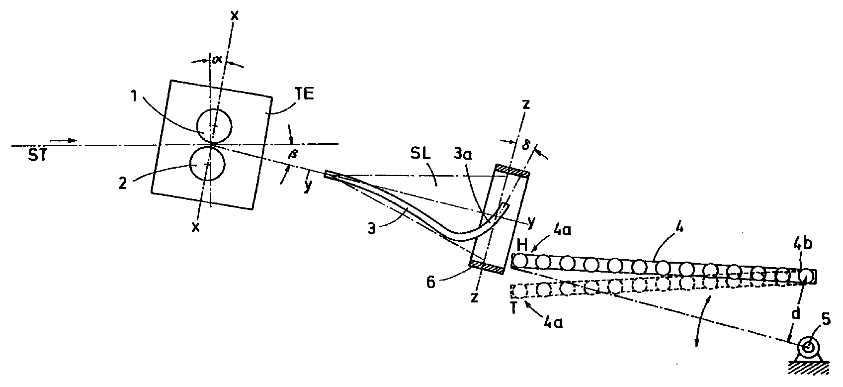
- the drawing shows the arrangement of the drive device, sling layer and conveyor in a schematic representation.
- the drive device TE with the drive rollers 1 and 2 is arranged.
- the common axis plane x-x lies at an angle ⁇ to Vertical.
- the looping device is behind the driving device TE SL arranged.
- the axis of rotation y-y of the laying tube 3 runs thereby at an angle ⁇ to the horizontal, while the laying arm 3a of the laying tube 3 at an angle ⁇ to the plane of rotation z-z of the devisrms lies.
- the conveyor here a roller table 4, is around Pivot axis 5, which is at a distance d below that Loop receiving end 4a of the opposite end 4b of the roller table 4 located in a vertical plane between an upper high position H, which is indicated in full lines and a low position T, which is indicated in broken lines, pivotable.
- the drive rollers 1, 2 rotate before the beginning of the wire strand at slightly higher speeds than the expected speed corresponding to the wire, and its opening gap is slight dimensioned larger than the wire diameter.
- the inclined arrangement of the common Axial plane of the drive rollers 1, 2 causes not only the drive but also a bending effect on the wire. This bending effect is with wire large diameter larger because of the lever arm with which the Driving rollers 1, 2 on the incoming in a horizontal plane Wire, is larger, i.e. the bending moment increases with increasing wire diameter. This facilitates the redirection of the Wire and reduces the resulting friction losses.
- the drive rollers 1, 2 even the ends of large diameter wires after this have left the wire mill, drive and to compensate for the Accelerate work in laying tube 3. This is due to the inclined Arrangement of the drive rollers 1, 2 supported.
- the loops are first formed in the laying arm 3a of the laying tube 3, which also determines the diameter of the sling.
- the exit the loops at an angle ⁇ to the plane of rotation causes one Movement of the emerging loops in the direction of the axis of rotation y-y of the laying arm 3a, the wire at high speeds up to 5 m / s reached. These speeds are at wires achieved with a small diameter.
- the position of the pivot axis 5 of the roller table 4 is selected so that when Always raise or lower the position of the first roller table roller 4a at the best distance from the laying arm 3a or its fixed guide ring 6 remains.
Landscapes
- Engineering & Computer Science (AREA)
- Mechanical Engineering (AREA)
- Winding, Rewinding, Material Storage Devices (AREA)
- Metal Rolling (AREA)
- Guides For Winding Or Rewinding, Or Guides For Filamentary Materials (AREA)
- Wire Processing (AREA)
- Ropes Or Cables (AREA)
- Tyre Moulding (AREA)
- Forwarding And Storing Of Filamentary Material (AREA)
Abstract
Eine Vorrichtung zur Bildung von Schlingen aus einem Drahtstrang
(ST), der aus einer Walzdrahtstraße austritt. Die Schlingen werden
von einem rotierenden Schlingenleger (SL) erzeugt. Der Walzdrahtstraße
sind eine Treibeinrichtung (TE), und dieser der Schlingenleger
(SL) und ein Rollgang (4) nachgeordnet. Auf diesem Rollgang (4)
legt der Schlingenleger (SL) die Schlingen ab. Die Treibeinrichtung
(TE) und der Schlingenleger (SL) sind mit vorbestimmten Neigungswinkeln
(α, β) fest angeordnet und der Rollgang (4) ist um eine
Achse (5) schwenkwinkelverstellbar.
Description
Die Erfindung betrifft eine Vorrichtung zur Bildung von Schlingen aus einem, aus einer Walzdrahtstraße austretenden Drahtstrang mittels eines rotierenden Schlingenlegers und deren Ablage auf einen, während des Ablegens transportbewegten Förderer, bei der der Walzdrahtstraße eine Treibeinrichtung, ein Schlingenleger und ein Rollgang, ein Kettenförderer oder dergleichen nachgeordnet sind und Treibeinrichtung und ggfs. auch der Schlingenleger geneigt zur Horizontalen angeordnet sind.The invention relates to a device for forming loops from a wire strand emerging from a wire rod mill by means of a rotating sling layer and its storage a conveyor which is moved during discarding and in which the Wire rod mill a driving device, a looping device and a Roller table, a chain conveyor or the like are subordinate and Driving device and possibly also the sling layer inclined to the horizontal are arranged.
Moderne Drahtwalzstraßen arbeiten mit immer höher werdenden Endgeschwindigkeiten, insb. beim Walzen von Draht mit kleinem Durchmesser. Es werden dabei Endgeschwindigkeiten von mehr als 100 m/s erreicht. Andererseits werden auch immer stärkere Abmessungen gewalzt, bis zu Drahtdurchmessern von über ca. 25 mm.Modern wire rolling mills work at ever increasing top speeds, especially when rolling wire with a small diameter. The final speeds are more than 100 m / s reached. On the other hand, increasingly larger dimensions rolled, up to wire diameters of over approx. 25 mm.
Diese sehr unterschiedlichen Walzparameter bringen Probleme bei der Ablage der Drahtschlingen des fertig gewalzten Drahtes auf den Förderer mit sich.These very different rolling parameters cause problems with the Storage of the wire loops of the finished rolled wire on the Conveyor with himself.
Nach dem Stand der Technik ist der Schlingenleger meist mit einem Winkel von etwa 10° zur Horizontalen fest angeordnet und die, diesem vorgeordnete Treibeinrichtung entweder in der Horizontalen oder ebenfalls unter dem gleichen oder einem kleineren Winkel angeordnet. According to the state of the art, the sling layer is usually with one Angle of about 10 ° to the horizontal and the, this upstream driver either in the horizontal or also arranged at the same or a smaller angle.
Um eine einwandfreie Ablage der Schlingen von Drähten mit kleinem Durchmesser unter sehr hohen Geschwindigkeiten einerseits und von großen Drahtdurchmessern mit geringeren Geschwindigkeiten andererseits zu erzielen, wurde bereits ein Schlingenleger vorgeschlagen, dessen Neigung zur Horizontalen veränderbar war. Für hohe Drahtgeschwindigkeiten beträgt der Neigungswinkel dabei z.B. 10° und für niedrige Geschwindigkeiten bis zu 30°. Diese Lösung brachte jedoch die folgenden, erheblichen Nachteile mit sich: Die unterschiedlichen Neigungen bedingen entsprechend veränderte Abstände zu den horizontalen Führungsebenen, d.h. es müssen jeweils entsprechend angepaßte unterschiedliche Umlenkführungen eingesetzt werden. Weiter sind schwenkbare Tragkonstruktionen für die Treibeinrichtung und den Schlingenleger notwendig. Diese Tragkonstruktionen sind nicht nur technisch aufwendig, sondern auch bei hohen Geschwindigkeiten anfällig gegen Schwingungen.To ensure a perfect placement of the loops of wires with small Diameter at very high speeds on the one hand and of large wire diameters with lower speeds on the other hand a sling layer has already been proposed, whose inclination to the horizontal was changeable. For high wire speeds the angle of inclination is e.g. 10 ° and for low speeds up to 30 °. However, this solution brought the following significant disadvantages: The different Inclinations cause the distances to the horizontal to change accordingly Management levels, i.e. it must be adjusted accordingly different deflection guides can be used. Are further swiveling support structures for the driving device and the Loop layer necessary. These support structures are not only technically complex, but also at high speeds susceptible to vibrations.
Der Erfindung liegt die Aufgabe zugrunde, diese Vorrichtungen so zu verbessern, daß unter Vermeidung sowohl der schwenkbaren Tragkonstruktionen und der verschiedenen Umlenkführungen, als auch der Schwingungsanfälligkeit der Tragkonstruktionen, die einwandfreie Ablage der Schlingen von Drahtstärken mit kleinen und auch großen Durchmessern ermöglicht wird.The invention has for its object these devices to improve that while avoiding both the pivoting support structures and the different deflection guides, as well as the Susceptibility to vibrations of the supporting structures, the flawless Storage of the loops of wire gauge with small and also large ones Diameters is made possible.
Diese Aufgabe wird dadurch gelöst, daß bei fester Anordnung von Treibeinrichtung und Schlingenleger in einem vorbestimmten Neigungswinkel, die Transportebene des, die Schlingen aufnehmenden Förderers schwenkwinkelverstellbar zur Horizontalen ausgebildet ist. Die Schwenkachse für die Schwenkwinkelverstellung des Förderers wird zweckmäßig mit Abstand unter dessen, dem Schlingenaufnahmeende abgewandten Ende angeordnet, während der Antrieb der Treibeinrichtung zweckmäßig bspw. über druckregelbare Pneumatik-KolbenZylinder-Aggregate regelbar und die Position der Tragrollen über Stellelemente, wie Stellschrauben einstellbar ist. This object is achieved in that with a fixed arrangement of Drive device and sling layer at a predetermined angle of inclination, the transport level of the conveyor taking up the slings is adjustable adjustable to the horizontal. The Swivel axis for the swivel angle adjustment of the conveyor expediently at a distance below the loop end arranged opposite end, while driving the driver Expedient, for example, via pressure-adjustable pneumatic piston-cylinder units adjustable and the position of the idlers via adjusting elements, how adjusting screws can be adjusted.
Die Erfindung wird anhand des in der Zeichnung dargestellten Ausführungsbeisplels näher erläutert.The invention is based on the exemplary embodiment shown in the drawing explained in more detail.
Die Zeichnung zeigt die Anordnung von Treibeinrichtung, Schlingenleger und Förderer in schematischer Darstellung.The drawing shows the arrangement of the drive device, sling layer and conveyor in a schematic representation.
Hinter dem Ausgang der nicht dargestellten Walzdrahtstraße, aus der
der Drahtstrang ST in Richtung des eingezeichneten Pfeiles austritt,
ist die Treibeinrichtung TE mit den Treibrollen 1 und 2 angeordnet.
Die gemeinsame Achsebene x-x liegt dabei in einem Winkel α zur
Vertikalen. Hinter der Treibeinrichtung TE ist der Schlingenleger
SL angeordnet. Die Rotationsachse y-y des Legerohres 3 verläuft
dabei in einem Winkel β zur Horizontalen, während der Legearm 3a
des Legerohres 3 in einem Winkel δ zur Rotationsebene z-z des
Legearms liegt. Der Förderer, hier ein Rollgang 4, ist um die
Schwenkachse 5, die sich mit einem Abstand d unterhalb des, dem
Schlingenaufnahmeende 4a abgewandten Endes 4b des Rollgangs 4
befindet, in einer vertikalen Ebene zwischen einer oberen Hoch-Position
H, die in vollen Linien angedeutet ist und einer Tief-Position
T, die in unterbrochenen Linien angedeutet ist, schwenkbar.Behind the exit of the wire rod mill, not shown, from the
the wire strand ST emerges in the direction of the arrow shown,
the drive device TE with the
Die Treibrollen 1, 2 drehen vor Einlauf des Anfangs des Drahtstranges
mit etwas höheren Drehzahlen als die der erwarteten Geschwindigkeit
des Drahtes entsprechende, und ihr Öffnungsspalt ist geringfügig
größer bemessen als der Drahtdurchmesser. Die Treibrollen 1,
2 werden, wenn der Anfang des Drahtes diese passiert hat und durch
die nicht dargestellte Führung hinter den Treibrollen 1, 2 nach
unten gelenkt wurde, geschlossen. Die geneigte Anordnung der gemeinsamen
Achsebene der Treibrollen 1, 2 bewirkt neben dem Treib- auch
einen Biegeeffekt auf den Draht. Dieser Biegeeffekt ist bei Draht
mit großem Durchmesser größer, weil der Hebelarm, mit dem die
Treibrollen 1, 2 auf den in einer waagerechten Ebene einlaufenden
Draht wirken, größer ist, d.h. das Biegemoment vergrößert sich mit
steigendem Drahtdurchmesser. Dies erleichtert die Umlenkung des
Drahtes und vermindert die dabei entstehenden Reibungsverluste.
Neben der beschriebenen Umlenkarbeit müssen die Treibrollen 1, 2
auch die Enden von Drähten mit großem Durchmesser, nachdem diese
die Drahtstraße verlassen haben, antreiben und zur Kompensation der
Arbeit im Legerohr 3 beschleunigen. Dies wird durch die geneigte
Anordnung der Treibrollen 1, 2 unterstützt.The
Die Schlingen werden zunächst im Legearm 3a des Legerohres 3 gebildet,
der auch den Durchmesser der Schlinge bestimmt. Der Austritt
der Schlingen in einem Winkel β zur Rotationsebene bewirkt eine
Bewegung der austretenden Schlingen in Richtung der Rotationsachse
y-y des Legearms 3a, die bei hohen Geschwindigkeiten des Drahtes
bis zu 5 m/s erreicht. Diese Geschwindigkeiten werden bei Drähten
mit kleinem Durchmesser erreicht. Diese weisen im walzwarmen Zustand
eine geringe Stabilität auf. Um trotz dieser geringen Stabilität
eine einwandfreie Ablage der Schlingen auf dem Rollgang 4 zu erreichen,
wird dieser in die mit T bezeichnete Tief-Position abgesenkt.
In dieser bremst der Rollgang 4 die aufgelegten Schlingen nur in
einem geringen Maße ab, weshalb es nicht zur Verformung des Drahtes
kommt.The loops are first formed in the
Beim Legen der Schlingen von Drähten mit größerem Durchmesser ist
deren Bewegungsgeschwindigkeit in Richtung der Rotationsachse y-y
des Legearms 3a gering. Die Schlingen weisen wegen des größeren
Drahtdurchmessers eine höhere Steifigkeit auf. Der Rollgang 4 wird
deshalb in diesem Fall in die Hoch-Position H geschwenkt. Damit
werden die Schlingen, unmittelbar nachdem sie den Legearm 3a verlassen
haben, erheblich stärker abgebremst und damit das rechtzeitige
Auflegen auf dem Rollgang 4 gewährleistet.When laying the loops of wires with larger diameter is
their speed of movement in the direction of the axis of rotation y-y
of the
Die Lage der Schwenkachse 5 des Rollgangs 4 ist so gewählt, daß beim
Heben bzw. Senken die Position der ersten Rollgangsrolle 4a stets
im günstigsten Abstand vom Legearm 3a bzw. dessen festen Führungsring
6 bleibt.The position of the
Claims (5)
dadurch gekennzeichnet,
daß bei fester Anordnung von Treibeinrichtung (TE) und Schlingenleger (SL) in einem vorbestimmten Neigungswinkel, der die Schlingen aufnehmende Förderer (4) schwenkwinkelverstellbar zur Horizontalen ausgebildet ist.Device for forming loops from a wire strand emerging from a wire rod mill by means of a rotating looping device and for depositing it on a conveyor which is moved during the depositing, in which a driving device, a looping device and a roller table, a chain conveyor or the like is arranged downstream of the wire rod mill and the like Looper and possibly also the drive device are arranged inclined to the horizontal,
characterized,
that with a fixed arrangement of the driving device (TE) and sling layer (SL) at a predetermined angle of inclination, the sling-receiving conveyor (4) is designed to be adjustable in relation to the horizontal.
dadurch gekennzeichnet,
daß die Schwenkachse (5) für die Winkelverstellung des Förderers (4) im Abstand (d) unterdessen, dem Schlingenaufnahmeende (4a) abgewandten Ende (4b) angeordnet ist.Device according to claim 1,
characterized,
that the pivot axis (5) for the angular adjustment of the conveyor (4) at a distance (d) meanwhile, the loop receiving end (4a) facing away from the end (4b) is arranged.
dadurch gekennzeichnet,
daß der Antrieb der Treibeinrichtung (TE) regelbar ist. Device according to claim 1,
characterized,
that the drive of the driving device (TE) can be regulated.
dadurch gekennzeichnet,
daß bei Antrieb beider Treibrollen (1, 2) der Treibeinrichtung (TR) deren Anpressung über druckregelbare Pneumatik-Kolben-Zylinder-Aggregate bewirkt wird.Device according to claim 3,
characterized,
that when both drive rollers (1, 2) of the drive device (TR) are driven, their pressure is brought about by pressure-controllable pneumatic piston-cylinder units.
dadurch gekennzeichnet,
daß die Position der Treibrollen (1, 2) der Treibeinrichtung (TR) über Stellelemente, wie Stellschrauben einstellbar ist.Device according to claims 3 and / or 4,
characterized,
that the position of the drive rollers (1, 2) of the drive device (TR) is adjustable via adjusting elements, such as adjusting screws.
Applications Claiming Priority (2)
| Application Number | Priority Date | Filing Date | Title |
|---|---|---|---|
| DE19725774A DE19725774A1 (en) | 1997-06-18 | 1997-06-18 | Device for forming loops from a wire strand emerging from a wire rod mill by means of a rotating looping device |
| DE19725774 | 1997-06-18 |
Publications (3)
| Publication Number | Publication Date |
|---|---|
| EP0885668A2 true EP0885668A2 (en) | 1998-12-23 |
| EP0885668A3 EP0885668A3 (en) | 2000-07-05 |
| EP0885668B1 EP0885668B1 (en) | 2002-11-27 |
Family
ID=7832859
Family Applications (1)
| Application Number | Title | Priority Date | Filing Date |
|---|---|---|---|
| EP98110736A Expired - Lifetime EP0885668B1 (en) | 1997-06-18 | 1998-06-12 | Coil forming head for forming loops from wire leaving a wire rolling mill |
Country Status (5)
| Country | Link |
|---|---|
| US (1) | US5944275A (en) |
| EP (1) | EP0885668B1 (en) |
| JP (1) | JPH1177154A (en) |
| AT (1) | ATE228404T1 (en) |
| DE (2) | DE19725774A1 (en) |
Cited By (1)
| Publication number | Priority date | Publication date | Assignee | Title |
|---|---|---|---|---|
| EP2017018A1 (en) * | 2007-07-16 | 2009-01-21 | SMS Meer GmbH | Method for producing wire and wire rolling mill |
Families Citing this family (4)
| Publication number | Priority date | Publication date | Assignee | Title |
|---|---|---|---|---|
| JP2000274140A (en) * | 1999-03-23 | 2000-10-03 | Koito Mfg Co Ltd | Power window safety device |
| DE102010025724B4 (en) * | 2010-07-01 | 2022-10-13 | Maag Automatik Gmbh | cutting bar |
| CN102974655B (en) * | 2012-12-12 | 2014-10-15 | 常州宝菱重工机械有限公司 | Steel belt drifting preventing device for Caro Searle steel belt reeling machine |
| BR112020021149A2 (en) * | 2018-05-07 | 2021-02-17 | Russula Corporation | coil forming loop forming system |
Family Cites Families (10)
| Publication number | Priority date | Publication date | Assignee | Title |
|---|---|---|---|---|
| US1295139A (en) * | 1915-12-04 | 1919-02-25 | Morgan Construction Co | Apparatus for coiling and cooling wire rods. |
| GB1024713A (en) * | 1962-08-24 | 1966-04-06 | Morgan Construction Co | Apparatus and process for the controlled cooling of rods |
| US3452785A (en) * | 1965-12-07 | 1969-07-01 | David William Mclean | Apparatus for depositing and conveying rod rings in sequence with rod forming means |
| US3490500A (en) * | 1966-11-05 | 1970-01-20 | Schloemann Ag | Plant for the treatment of rolled wire from the roll heat |
| IT1056788B (en) * | 1976-03-01 | 1982-02-20 | Properzi G | EXTRACTOR DEVICE FOR VERGELLA OR SIMILAR TO THE EXIT OF A ROLLER |
| DE2837912A1 (en) * | 1978-08-31 | 1980-03-13 | Moeller & Neumann Gmbh | Conveyor for cooling heated wire - has hydraulic jack to adjust slope of conveyor to minimise friction |
| IT8460459U1 (en) * | 1984-09-19 | 1986-03-19 | Danieli Off Mecc | Convertible spiral head shape |
| DE3537668A1 (en) * | 1985-10-23 | 1987-04-23 | Krupp Gmbh | Wire rod adjustment |
| AT396075B (en) * | 1990-11-20 | 1993-05-25 | Voest Alpine Ind Anlagen | METHOD FOR PUTING A WIRE IN CIRCULAR WINDINGS |
| US5312065A (en) * | 1992-02-05 | 1994-05-17 | Morgan Construction Company | Rod laying head with front and tail end ring control |
-
1997
- 1997-06-18 DE DE19725774A patent/DE19725774A1/en not_active Withdrawn
-
1998
- 1998-06-10 US US09/095,336 patent/US5944275A/en not_active Expired - Fee Related
- 1998-06-12 AT AT98110736T patent/ATE228404T1/en not_active IP Right Cessation
- 1998-06-12 DE DE59806402T patent/DE59806402D1/en not_active Expired - Fee Related
- 1998-06-12 EP EP98110736A patent/EP0885668B1/en not_active Expired - Lifetime
- 1998-06-15 JP JP10167381A patent/JPH1177154A/en not_active Withdrawn
Cited By (1)
| Publication number | Priority date | Publication date | Assignee | Title |
|---|---|---|---|---|
| EP2017018A1 (en) * | 2007-07-16 | 2009-01-21 | SMS Meer GmbH | Method for producing wire and wire rolling mill |
Also Published As
| Publication number | Publication date |
|---|---|
| US5944275A (en) | 1999-08-31 |
| EP0885668A3 (en) | 2000-07-05 |
| EP0885668B1 (en) | 2002-11-27 |
| DE59806402D1 (en) | 2003-01-09 |
| JPH1177154A (en) | 1999-03-23 |
| ATE228404T1 (en) | 2002-12-15 |
| DE19725774A1 (en) | 1998-12-24 |
Similar Documents
| Publication | Publication Date | Title |
|---|---|---|
| DE102013002017B4 (en) | Winding device and method for a strand-shaped wound material | |
| DE102007045425A1 (en) | Method and device for winding metal strips on a winding mandrel | |
| DE2431784C3 (en) | Cable guide roller with bearing construction | |
| DE3314319C2 (en) | Device for splicing tapes | |
| EP3331792B1 (en) | Device for filling a can with a sliver | |
| DE102013002023B4 (en) | Device and method for winding a strand-shaped winding material | |
| EP0885668A2 (en) | Coil forming head for forming loops from wire leaving a wire rolling mill | |
| DE3430218A1 (en) | DEVICE FOR CORRECTING ZIGZAG RUN WITH CONTINUOUS TAPE MATERIAL | |
| EP0593951A2 (en) | Spinning device | |
| EP0972669A1 (en) | Stringing apparatus for electrical catenary line | |
| EP0432531A1 (en) | Apparatus for cooling wire rods | |
| AT408195B (en) | DRAINAGE DEVICE | |
| EP1038651A2 (en) | Flattening and haul-off apparatus for a blow moulded plastic tubular film | |
| AT11798U1 (en) | ROTOR REFERENCE UNIT FOR RUNNING TIMBER WIRE | |
| DE3344673C2 (en) | Device for lifting and / or deflecting strip material from the circumference of a strip bundle held in a pay-off reel or the like | |
| EP1587973B1 (en) | Fiber conveying and discarding device to be connected to a carder | |
| DE10016021A1 (en) | Swing crane has swing frames with rollers on a carrier at the foundation column to give a positive cable feed and wide swing crane rotating tower rotations without cable contact | |
| DE4318632A1 (en) | Loading device for material rolls, in particular for paper rolls | |
| DE6917132U (en) | TREE MACHINE WITH WINDING ROLLER FOR WEBWARE OF ALL KINDS | |
| DE3018052C2 (en) | ||
| DE2130020A1 (en) | Tree machine | |
| DE3915979C2 (en) | ||
| DE2632132C2 (en) | Device for screw cutting a tubular fabric | |
| DD214773A1 (en) | DEVICE FOR WIRE-WINDING LEGS FOR THE QUALITY-ORIENTED STORAGE OF WIRE THREADS | |
| DE3918270C2 (en) | Rolling mill |
Legal Events
| Date | Code | Title | Description |
|---|---|---|---|
| PUAI | Public reference made under article 153(3) epc to a published international application that has entered the european phase |
Free format text: ORIGINAL CODE: 0009012 |
|
| 17P | Request for examination filed |
Effective date: 19980612 |
|
| AK | Designated contracting states |
Kind code of ref document: A2 Designated state(s): AT DE IT SE |
|
| AX | Request for extension of the european patent |
Free format text: AL;LT;LV;MK;RO;SI |
|
| PUAL | Search report despatched |
Free format text: ORIGINAL CODE: 0009013 |
|
| RAP1 | Party data changed (applicant data changed or rights of an application transferred) |
Owner name: SMS DEMAG AG |
|
| AK | Designated contracting states |
Kind code of ref document: A3 Designated state(s): AT BE CH CY DE DK ES FI FR GB GR IE IT LI LU MC NL PT SE |
|
| AX | Request for extension of the european patent |
Free format text: AL;LT;LV;MK;RO;SI |
|
| RIC1 | Information provided on ipc code assigned before grant |
Free format text: 7B 21C 47/14 A, 7B 21C 47/26 B |
|
| AKX | Designation fees paid |
Free format text: AT DE IT SE |
|
| GRAG | Despatch of communication of intention to grant |
Free format text: ORIGINAL CODE: EPIDOS AGRA |
|
| 17Q | First examination report despatched |
Effective date: 20020228 |
|
| GRAG | Despatch of communication of intention to grant |
Free format text: ORIGINAL CODE: EPIDOS AGRA |
|
| GRAH | Despatch of communication of intention to grant a patent |
Free format text: ORIGINAL CODE: EPIDOS IGRA |
|
| GRAH | Despatch of communication of intention to grant a patent |
Free format text: ORIGINAL CODE: EPIDOS IGRA |
|
| GRAA | (expected) grant |
Free format text: ORIGINAL CODE: 0009210 |
|
| AK | Designated contracting states |
Kind code of ref document: B1 Designated state(s): AT DE IT SE |
|
| REF | Corresponds to: |
Ref document number: 228404 Country of ref document: AT Date of ref document: 20021215 Kind code of ref document: T |
|
| REF | Corresponds to: |
Ref document number: 59806402 Country of ref document: DE Date of ref document: 20030109 |
|
| PLBE | No opposition filed within time limit |
Free format text: ORIGINAL CODE: 0009261 |
|
| STAA | Information on the status of an ep patent application or granted ep patent |
Free format text: STATUS: NO OPPOSITION FILED WITHIN TIME LIMIT |
|
| 26N | No opposition filed |
Effective date: 20030828 |
|
| PGFP | Annual fee paid to national office [announced via postgrant information from national office to epo] |
Ref country code: SE Payment date: 20040603 Year of fee payment: 7 Ref country code: AT Payment date: 20040603 Year of fee payment: 7 |
|
| PGFP | Annual fee paid to national office [announced via postgrant information from national office to epo] |
Ref country code: DE Payment date: 20040604 Year of fee payment: 7 |
|
| PG25 | Lapsed in a contracting state [announced via postgrant information from national office to epo] |
Ref country code: IT Free format text: LAPSE BECAUSE OF NON-PAYMENT OF DUE FEES Effective date: 20050612 Ref country code: AT Free format text: LAPSE BECAUSE OF NON-PAYMENT OF DUE FEES Effective date: 20050612 |
|
| PG25 | Lapsed in a contracting state [announced via postgrant information from national office to epo] |
Ref country code: SE Free format text: LAPSE BECAUSE OF NON-PAYMENT OF DUE FEES Effective date: 20050613 |
|
| PG25 | Lapsed in a contracting state [announced via postgrant information from national office to epo] |
Ref country code: DE Free format text: LAPSE BECAUSE OF NON-PAYMENT OF DUE FEES Effective date: 20060103 |
|
| EUG | Se: european patent has lapsed |