EP2017018A1 - Method for producing wire and wire rolling mill - Google Patents
Method for producing wire and wire rolling mill Download PDFInfo
- Publication number
- EP2017018A1 EP2017018A1 EP08009059A EP08009059A EP2017018A1 EP 2017018 A1 EP2017018 A1 EP 2017018A1 EP 08009059 A EP08009059 A EP 08009059A EP 08009059 A EP08009059 A EP 08009059A EP 2017018 A1 EP2017018 A1 EP 2017018A1
- Authority
- EP
- European Patent Office
- Prior art keywords
- wire
- driver
- cooling
- rolling mill
- behind
- Prior art date
- Legal status (The legal status is an assumption and is not a legal conclusion. Google has not performed a legal analysis and makes no representation as to the accuracy of the status listed.)
- Granted
Links
Images
Classifications
-
- B—PERFORMING OPERATIONS; TRANSPORTING
- B21—MECHANICAL METAL-WORKING WITHOUT ESSENTIALLY REMOVING MATERIAL; PUNCHING METAL
- B21B—ROLLING OF METAL
- B21B41/00—Guiding, conveying, or accumulating easily-flexible work, e.g. wire, sheet metal bands, in loops or curves; Loop lifters
- B21B41/08—Guiding, conveying, or accumulating easily-flexible work, e.g. wire, sheet metal bands, in loops or curves; Loop lifters without overall change in the general direction of movement of the work
-
- B—PERFORMING OPERATIONS; TRANSPORTING
- B21—MECHANICAL METAL-WORKING WITHOUT ESSENTIALLY REMOVING MATERIAL; PUNCHING METAL
- B21C—MANUFACTURE OF METAL SHEETS, WIRE, RODS, TUBES, PROFILES OR LIKE SEMI-MANUFACTURED PRODUCTS OTHERWISE THAN BY ROLLING; AUXILIARY OPERATIONS USED IN CONNECTION WITH METAL-WORKING WITHOUT ESSENTIALLY REMOVING MATERIAL
- B21C47/00—Winding-up, coiling or winding-off metal wire, metal band or other flexible metal material characterised by features relevant to metal processing only
- B21C47/26—Special arrangements with regard to simultaneous or subsequent treatment of the material
-
- B—PERFORMING OPERATIONS; TRANSPORTING
- B21—MECHANICAL METAL-WORKING WITHOUT ESSENTIALLY REMOVING MATERIAL; PUNCHING METAL
- B21C—MANUFACTURE OF METAL SHEETS, WIRE, RODS, TUBES, PROFILES OR LIKE SEMI-MANUFACTURED PRODUCTS OTHERWISE THAN BY ROLLING; AUXILIARY OPERATIONS USED IN CONNECTION WITH METAL-WORKING WITHOUT ESSENTIALLY REMOVING MATERIAL
- B21C49/00—Devices for temporarily accumulating material
-
- B—PERFORMING OPERATIONS; TRANSPORTING
- B21—MECHANICAL METAL-WORKING WITHOUT ESSENTIALLY REMOVING MATERIAL; PUNCHING METAL
- B21B—ROLLING OF METAL
- B21B15/00—Arrangements for performing additional metal-working operations specially combined with or arranged in, or specially adapted for use in connection with, metal-rolling mills
- B21B2015/0057—Coiling the rolled product
Definitions
- the invention relates to a method for producing wire, in which the wire is rolled in at least one finishing stand of a wire rolling mill, wherein the rolled wire passes behind the final finishing stand in the conveying direction a cooling and / or compensation path, wherein the wire by a at the end of Cooling and / or balancing path arranged first driver is pulled through the cooling and / or balancing section and wherein in the conveying direction behind the first driver a Windungsleger for the wire is arranged, with which it can be stored in turns. Furthermore, the invention relates to a wire rolling mill for carrying out the method.
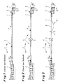
- the wire In wire rolling, in a final rolling process, the wire is rolled in a finishing block from a number of finishing stands and brought to the final desired wire diameter. The wire then passes through a cooling and equalizing section before being laid in turns by means of a layer.
- a driver 5 is arranged, which pulls the wire 1 through the cooling and balancing section 4.
- a Windungsleger 6 is arranged, which deposits the wire 1 in a known manner in turns.
- Fig. 2 differs from the one after Fig. 1 essentially only in that a further driver 5 is arranged here within the cooling and equalizing section 4, which keeps the wire 1 under tension as it passes the cooling and equalizing section 4.
- the wire 1 thus leaves the finished block or its finishing stands 2 at the speed V D , which, however, is not absolutely constant. Rather, the speed V D fluctuates around an average value.
- This variation in speed results in that the shed shape of the wire is not optimal, that is, the winding diameter of the wire 1 laid down by the layer is not constant, since the layer rotates at a constant speed, but the wire has a non-constant speed when entering the layer.
- the drive of the second driver can be controlled so that the loop height is within a predetermined range of values.
- the drive speed of the Windungslegers is further controlled or regulated in dependence on the conveying speed of the second driver.
- the wire is held in the cooling and / or compensation path between the last finishing stand and the first driver of this preferably under a predetermined train. Furthermore, it can be provided that within the cooling and / or compensation path, a further driver is arranged, which exerts a tensile force on the wire.
- the proposed wire rolling mill is characterized according to the invention in that in the conveying direction behind the first driver and before the Windungsleger a second driver is arranged, which is driven so that the wire between the two drivers forms a loop with a measured from the straight nominal line loop height ,
- control means for detecting the loop height of the loop are provided. Furthermore, control means are advantageously present which are connected to the measuring means and can influence a drive motor for the second driver.
- the control means can also influence a drive motor of the layer, so that in this way a synchronization of the operating speed of the second driver and the Windungslegers can be made.
- the rolling process is thus decoupled from the laying process.
- Fig. 3 is a section of a wire rolling mill 3 to see, which is constructed analogously to the solution described above according to the prior art (s. Fig. 1 and 2 ).
- the wire 1 leaves in the conveying direction F the finishing stands 2 of a finished block in order to reach a cooling and equalizing section 4.
- the wire 1 is pulled by the cooling and equalizing section 4 by means of a first driver 5; the driver 5 holds the wire 1 when passing the cooling and balancing section 4 under train.
- the driving speed of the first driver 5 is determined by the wire speed V D of the wire 1 behind the finished block.
- the wire 1 has the velocity V D , which is not constant, but fluctuates around an average value.
- Behind the cooling and equalizing section 4 of the wire 1 enters a Windungsleger 6, which deposits it in a known manner in turns, z. B. on a conveyor belt.
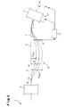
- a second driver 7 is arranged in the conveying direction F behind the first driver 5 and before the Windungsleger 6.
- the two drivers 5 and 7 are spaced apart.
- the second driver 7 is selectively operated so that the wire 1 between the two drivers 5 and 7 forms a loop 8.
- the loop 8 has a loop height H, which is measured from the straight line or ideal line 9 from.
- the second driver 7 conveys the wire 1 at a speed V T , which is kept substantially constant and on account of which the winding diameter of the wire results when it is laid down by the layer 6. Namely, the second driver 7 is operated at a constant speed V T , wherein the drive speed of the coil former 6 is coupled to the drive speed of the second driver 7.
- Fig. 4 Details are in Fig. 4 shown.
- the wire 1 is not guided linearly along the nominal line 9 between the two drivers 5 and 7, but curved, so that the loop 8 is formed.
- the loop 8 has a loop height H, which may move between a predeterminable minimum value H min and a maximum value H max .
- the respective courses of the wire 1 are shown with dashed lines.
- the current value of the loop height H is determined by means of a measuring means 10, in which it is z. B. can act to a light barrier, which can measure the maximum deflection of the wire 1 from the target line 9.
- the value determined by the measuring means 10 for the loop height H is fed to a control means 11.
- the control means 11 drive a drive motor 12 for the second driver 7 so that the loop height H is within the allowable range. If the value of the loop height becomes too large, the drive motor 12 is caused to rotate faster, and if the value becomes too small, the drive motor 12 becomes slower. The loop height H is thus kept in the closed loop at a desired value.
- control means 11 can also take corresponding effect on the drive of the Windungslegers 6, so that the operating speeds of the second driver 7 and that of the Windungslegers 6 are synchronized. The result is laid turns with uniform winding diameter.
Landscapes
- Engineering & Computer Science (AREA)
- Mechanical Engineering (AREA)
- Winding, Rewinding, Material Storage Devices (AREA)
- Metal Rolling (AREA)
Abstract
Description
Die Erfindung betrifft ein Verfahren zum Herstellen von Draht, bei dem der Draht in mindestens einem Fertiggerüst eines Drahtwalzwerks gewalzt wird, wobei der gewalzte Draht hinter dem in Förderrichtung letzten Fertiggerüst eine Kühl- und/oder Ausgleichsstrecke passiert, wobei der Draht durch einen am Ende der Kühlund/oder Ausgleichsstrecke angeordneten ersten Treiber durch die Kühl- und/oder Ausgleichsstrecke gezogen wird und wobei in Förderrichtung hinter dem ersten Treiber ein Windungsleger für den Draht angeordnet ist, mit dem er in Windungen abgelegt werden kann. Des weiteren betrifft die Erfindung ein Drahtwalzwerk zur Durchführung des Verfahrens.The invention relates to a method for producing wire, in which the wire is rolled in at least one finishing stand of a wire rolling mill, wherein the rolled wire passes behind the final finishing stand in the conveying direction a cooling and / or compensation path, wherein the wire by a at the end of Cooling and / or balancing path arranged first driver is pulled through the cooling and / or balancing section and wherein in the conveying direction behind the first driver a Windungsleger for the wire is arranged, with which it can be stored in turns. Furthermore, the invention relates to a wire rolling mill for carrying out the method.
Beim Walzen von Draht wird der Draht in einem letzten Walzprozess in einem Fertigblock von einer Anzahl Fertiggerüsten gewalzt und auf den endgültigen gewünschten Drahtdurchmesser gebracht. Anschließend durchläuft der Draht eine Kühl- und Ausgleichsstrecke, bevor er mittels eines Windungslegers in Windungen abgelegt wird.In wire rolling, in a final rolling process, the wire is rolled in a finishing block from a number of finishing stands and brought to the final desired wire diameter. The wire then passes through a cooling and equalizing section before being laid in turns by means of a layer.
Derartige Lösungen gemäß dem Stand der Technik sind für zwei mögliche Ausgestaltungen in den
Er verlässt den Fertigblock in Förderrichtung F mit einer Geschwindigkeit VD. Hinter dem Fertigblock gelangt der Draht 1 in eine Kühl- und Ausgleichsstrecke 4. Gemäß
Die Lösung gemäß
Dargestellt ist in beiden Figuren, dass aufgrund der Konzeption der Anlage der Draht 1 auch im Bereich des Treibers 5 und des Windungslegers 6 die Geschwindigkeit VD hat, mit der der Draht 1 den Fertigblock verlässt.It is shown in both figures that due to the design of the system, the
Der Draht 1 verlässt somit den Fertigblock bzw. dessen Fertiggerüste 2 mit der Geschwindigkeit VD, die allerdings nicht absolut konstant ist. Vielmehr schwankt die Geschwindigkeit VD um einen Mittelwert. Diese Geschwindigkeitsschwankung führt dazu, dass das Legebild des Drahtes nicht optimal ist, d. h. der Windungsdurchmesser des vom Windungsleger abgelegten Drahtes 1 ist nicht konstant, da der Windungsleger mit konstanter Drehzahl rotiert, der Draht beim Eintritt in den Windungsleger jedoch eine nicht-konstante Geschwindigkeit aufweist.The
Der Erfindung liegt daher die Aufgabe zugrunde, ein Verfahren sowie ein zugehöriges Drahtwalzwerk zu schaffen, mit denen es möglich ist, ein verbessertes Legebild des vom Windungsleger abgelegten Drahtes zu erreichen, insbesondere den Draht mit einem möglichst konstanten Windungsdurchmesser abzulegen.The invention is therefore based on the object to provide a method and an associated wire rolling mill, with which it is possible to achieve an improved shingling of the laid wire from the layer, in particular to deposit the wire with a very constant winding diameter.
Diese Aufgabe wird durch die Erfindung verfahrensgemäß dadurch gekennzeichnet, dass ein in Förderrichtung hinter dem ersten Treiber und vor dem Windungsleger angeordneter zweite Treiber so betrieben wird, dass der Draht zwischen den beiden Treibern eine Schlinge mit einer von der geraden Solllinie aus gemessenen Schlingenhöhe bildet.This object is achieved by the invention according to the method characterized in that in the conveying direction behind the first driver and before the Windungsleger arranged second driver is operated so that the wire between the two drivers forms a loop with a measured from the straight nominal line loop height.
Der Antrieb des zweiten Treibers kann dabei so geregelt werden, dass die Schlingenhöhe innerhalb eines vorgegebenen Wertebereichs liegt.The drive of the second driver can be controlled so that the loop height is within a predetermined range of values.
Vorzugsweise wird weiterhin die Antriebsgeschwindigkeit des Windungslegers in Abhängigkeit der Fördergeschwindigkeit des zweiten Treibers gesteuert oder geregelt.Preferably, the drive speed of the Windungslegers is further controlled or regulated in dependence on the conveying speed of the second driver.
Der Draht wird in der Kühl- und/oder Ausgleichsstrecke zwischen dem letzten Fertiggerüst und dem ersten Treiber von diesem vorzugsweise unter einem vorgegebenen Zug gehalten. Weiterhin kann vorgesehen sein, dass innerhalb der Kühlund/oder Ausgleichsstrecke ein weiterer Treiber angeordnet ist, der auf den Draht eine Zugkraft ausübt.The wire is held in the cooling and / or compensation path between the last finishing stand and the first driver of this preferably under a predetermined train. Furthermore, it can be provided that within the cooling and / or compensation path, a further driver is arranged, which exerts a tensile force on the wire.
Das vorgeschlagene Drahtwalzwerk zeichnet sich erfindungsgemäß dadurch aus, dass in Förderrichtung hinter dem ersten Treiber und vor dem Windungsleger ein zweiter Treiber angeordnet ist, der so antreibbar ist, dass der Draht zwischen den beiden Treibern eine Schlinge mit einer von der geraden Solllinie aus gemessenen Schlingenhöhe bildet.The proposed wire rolling mill is characterized according to the invention in that in the conveying direction behind the first driver and before the Windungsleger a second driver is arranged, which is driven so that the wire between the two drivers forms a loop with a measured from the straight nominal line loop height ,
Dabei sind zur Regelung der Größe der Schlinge bevorzugt Messmittel zur Erfassung der Schlingenhöhe der Schlinge vorgesehen. Ferner sind mit Vorteil Regelmittel vorhanden, die mit dem Messmittel in Verbindung stehen und einen Antriebsmotor für den zweiten Treiber beeinflussen können.In this case, to control the size of the loop preferably measuring means for detecting the loop height of the loop are provided. Furthermore, control means are advantageously present which are connected to the measuring means and can influence a drive motor for the second driver.
Die Regelmittel können auch einen Antriebsmotor des Windungslegers beeinflussen, so dass auf diese Weise eine Synchronisation der Arbeitsgeschwindigkeit des zweiten Treibers und des Windungslegers vorgenommen werden kann.The control means can also influence a drive motor of the layer, so that in this way a synchronization of the operating speed of the second driver and the Windungslegers can be made.
Mit dem erfindungsgemäßen Vorschlag wird erreicht, dass mit relativ einfachen Mitteln sichergestellt werden kann, dass der Draht vom Windungsleger mit konstantem Durchmesser abgelegt werden kann. Schwankungen in der Drahtgeschwindigkeit, die hinter dem Fertigblock vorliegen, können in einfacher Weise ausgeglichen werden.With the proposal according to the invention it is achieved that it can be ensured with relatively simple means that the wire can be stored by the layer with a constant diameter. Variations in the wire speed, which are present behind the finished block, can be compensated in a simple manner.
Der Walzprozess ist damit vom Legeprozess entkoppelt.The rolling process is thus decoupled from the laying process.
In vorteilhafter Weise ergeben sich bessere Drahtbunde, geringere Probleme mit Abweichungen der Durchmesser der Windungen und weniger Stillstände der Anlage.Advantageously, there are better wire coils, fewer problems with deviations in the diameter of the turns and less downtime of the system.
In der Zeichnung ist ein Ausführungsbeispiel der Erfindung dargestellt. Es zeigen:
- Fig. 1
- schematisch einen Ausschnitt aus einem Drahtwalzwerk mit einem Fer- tigblock, einer Kühl- und Ausgleichsstrecke, einem Treiber und einem Windungsleger gemäß dem Stand der Technik;
- Fig. 2
- eine zu
Fig. 1 alternative Ausgestaltung eines Drahtwalzwerks gemäß dem Stand der Technik; - Fig. 3
- in der Darstellung nach den
Figuren 1 und 2 - Fig. 4
- eine vergrößerte Darstellung einer Einzelheit von
Fig. 3 , wobei der Be- reich zwischen zwei Treibern dargestellt ist.
- Fig. 1
- schematically a section of a wire rolling mill with a finished block, a cooling and balancing section, a driver and a Windungsleger according to the prior art;
- Fig. 2
- one too
Fig. 1 alternative embodiment of a wire rolling mill according to the prior art; - Fig. 3
- in the illustration after the
Figures 1 and 2 a section of a wire rolling mill according to an embodiment of the invention; and - Fig. 4
- an enlarged view of a detail of
Fig. 3 , where the area between two drivers is shown.
In
Wesentlich ist, dass in Förderrichtung F hinter dem ersten Treiber 5 und vor dem Windungsleger 6 ein zweiter Treiber 7 angeordnet ist. Die beiden Treiber 5 und 7 sind voneinander beabstandet. Der zweite Treiber 7 wird dabei gezielt so betrieben, dass der Draht 1 zwischen den beiden Treibern 5 und 7 eine Schlinge 8 bildet. Wie in
Der zweite Treiber 7 fördert den Draht 1 mit einer Geschwindigkeit VT, die weitgehend konstant gehalten wird und aufgrund deren sich der Windungsdurchmesser des Drahts ergibt, wenn er vom Windungsleger 6 abgelegt wird. Der zweite Treiber 7 wird nämlich mit einer konstanten Geschwindigkeit VT betrieben, wobei die Antriebsgeschwindigkeit des Windungslegers 6 an die Antriebsgeschwindigkeit des zweiten Treibers 7 gekoppelt ist.The
Schwankungen in der Geschwindigkeit VD können auf diese Weise mittels der Schlinge 8 ausgeglichen werden, und die Zufuhr des Drahts 1 in den Windungsleger 6 erfolgt mittels des zweiten Treibers 7 mit konstanter Geschwindigkeit VT. Dies führt zu einem optimalen Legebild, da der Windungsdurchmesser konstant ist.Variations in the speed V D can be compensated in this way by means of the
Details hierzu sind in
Der aktuelle Wert der Schlingenhöhe H wird mittels eines Messmittels 10 ermittelt, bei dem es sich z. B. um eine Lichtschranke handeln kann, die die maximale Auslenkung des Drahts 1 von der Solllinie 9 messen kann. Der von dem Messmittel 10 ermittelte Wert für die Schlingenhöhe H wird einem Regelmittel 11 zugeführt.The current value of the loop height H is determined by means of a measuring means 10, in which it is z. B. can act to a light barrier, which can measure the maximum deflection of the
Die Regelmittel 11 steuern einen Antriebsmotor 12 für den zweiten Treiber 7 so an, dass die Schlingenhöhe H innerhalb des zulässigen Bereichs liegt. Wird der Wert für die Schlingenhöhe zu groß, wird der Antriebsmotor 12 zu einem schnelleren Drehen veranlasst, wird der Wert zu klein, wird der Antriebsmotor 12 langsamer. Die Schlingenhöhe H wird also im geschlossenen Regelkreis auf einem gewünschten Wert gehalten.The control means 11 drive a
Wie in
- 11
- Drahtwire
- 22
- Fertiggerüstfinishing stand
- 33
- DrahtwalzwerkWire rod mill
- 44
- Kühl- und/oder AusgleichsstreckeCooling and / or balancing section
- 55
- erster Treiberfirst driver
- 66
- Windungslegerlaying head
- 77
- zweiter Treibersecond driver
- 88th
- Schlingeloop
- 99
- Solllinietarget line
- 1010
- Messmittelmeasuring Equipment
- 1111
- Regelmittelcontrol means
- 1212
- Antriebsmotordrive motor
- FF
- Förderrichtungconveying direction
- HH
- Schlingenhöheloop height
- Hmin H min
- minimale Schlingenhöheminimum loop height
- Hmax H max
- maximale Schlingenhöhemaximum loop height
- VD V D
- Geschwindigkeit des Drahts hinter dem FertiggerüstSpeed of the wire behind the finishing stand
- VT V T
- Geschwindigkeit des Drahts hinter dem zweiten TreiberSpeed of the wire behind the second driver
Claims (10)
dadurch gekennzeichnet,
dass ein in Förderrichtung (F) hinter dem ersten Treiber (5) und vor dem Windungsleger (6) angeordneter zweiter Treiber (7) so betrieben wird, dass der Draht (1) zwischen den beiden Treibern (5, 7) eine Schlinge (8) mit einer von der geraden Solllinie (9) aus gemessenen Schlingenhöhe (H) bildet.Method for producing wire (1), in which the wire (1) is rolled in at least one finishing stand (2) of a wire rolling mill (3), the rolled wire (1) being behind the last finishing stand (2) in the conveying direction (F) a cooling and / or compensating section (4) passes, the wire (1) being pulled through the cooling and / or compensating section (4) through a first driver (5) arranged at the end of the cooling and / or equalizing section (4) and wherein in the conveying direction (F) behind the first driver (5) a Windungsleger (6) for the wire (1) is arranged, with which it can be stored in turns,
characterized,
that in the conveying direction (F) behind the first driver (5) and in front of the laying head (6) arranged second driver (7) is operated so that the wire (1) between the two drivers (5, 7) has a loop (8 ) with one of the straight line (9) from measured loop height (H) forms.
dadurch gekennzeichnet,
dass der Antrieb des zweiten Treibers (7) so geregelt wird, dass die Schlingenhöhe (H) innerhalb eines vorgegebenen Wertebereichs (Hmin, Hmax) liegt.Method according to claim 1,
characterized,
that the drive of the second driver (7) is controlled so that the loop height (H) within a predetermined range of values (H min, H max).
dadurch gekennzeichnet,
dass die Antriebsgeschwindigkeit des Windungslegers (6) in Abhängigkeit der Fördergeschwindigkeit (VT) des zweiten Treibers (7) gesteuert oder geregelt wird.Method according to claim 1 or 2,
characterized,
in that the drive speed of the coil former (6) is controlled or regulated as a function of the conveying speed (V T ) of the second driver (7).
dadurch gekennzeichnet,
dass der Draht (1) in der Kühl- und/oder Ausgleichsstrecke (4) zwischen dem letzten Fertiggerüst (2) und dem ersten Treiber (5) von diesem unter einem vorgegebenen Zug gehalten wird.Method according to one of claims 1 to 3,
characterized,
in that the wire (1) in the cooling and / or equalizing section (4) between the last finishing stand (2) and the first driver (5) is held by the latter under a predetermined tension.
dadurch gekennzeichnet,
dass innerhalb der Kühl- und/oder Ausgleichsstrecke (4) ein weiterer Treiber (5) angeordnet ist, der auf den Draht (1) eine Zugkraft ausübt.Method according to one of claims 1 to 4,
characterized,
in that a further driver (5), which exerts a pulling force on the wire (1), is arranged within the cooling and / or compensation path (4).
dadurch gekennzeichnet,
dass in Förderrichtung (F) hinter dem ersten Treiber (5) und vor dem Windungsleger (6) ein zweiter Treiber (7) angeordnet ist, der so antreibbar ist, dass der Draht (1) zwischen den beiden Treibern (5, 7) eine Schlinge (8) mit einer von der geraden Solllinie (9) aus gemessenen Schlingenhöhe (H) bildet.Wire rolling mill (3) with at least one finishing stand (2) for rolling the wire (1), wherein behind the last in the conveying direction (F) finishing stand (2) a cooling and / or compensation path (4) for the wire (1) is arranged , wherein at the end of the cooling and / or balancing section (4), a first driver (5) is arranged, with which the wire (1) can be pulled through the cooling and / or balancing section (3), and wherein in the conveying direction ( F) behind the first driver (5) a Windungsleger (6) for the wire (1) is arranged, in particular for carrying out the method according to one of claims 1 to 5,
characterized,
that in the conveying direction (F) behind the first driver (5) and before the Windungsleger (6) a second driver (7) is arranged, which is drivable so that the wire (1) between the two drivers (5, 7) a Sling (8) with one of the straight line (9) from measured loop height (H) forms.
gekennzeichnet durch
Messmittel (10) zur Erfassung der Schlingenhöhe (H) der Schlinge (8).Wire rolling mill according to claim 6,
marked by
Measuring means (10) for detecting the loop height (H) of the loop (8).
gekennzeichnet durch
Regelmittel (11), die mit dem Messmittel (10) in Verbindung stehen und einem Antriebsmotor (12) für den zweiten Treiber (7) zugeordnet sind.Wire rolling mill according to claim 7,
marked by
Control means (11) associated with the measuring means (10) and associated with a drive motor (12) for the second driver (7).
dadurch gekennzeichnet,
dass die Regelmittel (11) einem Antriebsmotor des Windungslegers (6) zugeordnet sind.Wire rolling mill according to claim 8,
characterized,
in that the control means (11) are associated with a drive motor of the layer (6).
dadurch gekennzeichnet,
dass innerhalb der Kühl- und/oder Ausgleichsstrecke (4) ein weiterer Treiber (5) angeordnet ist.Wire rolling mill according to one of claims 6 to 9,
characterized,
in that a further driver (5) is arranged within the cooling and / or equalizing section (4).
Applications Claiming Priority (1)
| Application Number | Priority Date | Filing Date | Title |
|---|---|---|---|
| DE102007032987A DE102007032987A1 (en) | 2007-07-16 | 2007-07-16 | Method for producing wire and wire rolling mill |
Publications (2)
| Publication Number | Publication Date |
|---|---|
| EP2017018A1 true EP2017018A1 (en) | 2009-01-21 |
| EP2017018B1 EP2017018B1 (en) | 2012-04-18 |
Family
ID=39512580
Family Applications (1)
| Application Number | Title | Priority Date | Filing Date |
|---|---|---|---|
| EP08009059A Not-in-force EP2017018B1 (en) | 2007-07-16 | 2008-05-16 | Method for producing wire and wire rolling mill |
Country Status (4)
| Country | Link |
|---|---|
| US (1) | US8375760B2 (en) |
| EP (1) | EP2017018B1 (en) |
| AT (1) | ATE553862T1 (en) |
| DE (1) | DE102007032987A1 (en) |
Cited By (1)
| Publication number | Priority date | Publication date | Assignee | Title |
|---|---|---|---|---|
| CN104384218A (en) * | 2014-10-14 | 2015-03-04 | 西南铝业(集团)有限责任公司 | Production technology of extruder |
Families Citing this family (1)
| Publication number | Priority date | Publication date | Assignee | Title |
|---|---|---|---|---|
| CN112157121B (en) * | 2020-09-25 | 2022-07-19 | 攀钢集团研究院有限公司 | Preparation method of 30MnSi hot-rolled wire rod |
Citations (5)
| Publication number | Priority date | Publication date | Assignee | Title |
|---|---|---|---|---|
| DE3601753A1 (en) * | 1985-07-29 | 1987-01-29 | Thaelmann Schwermaschbau Veb | METHOD AND DEVICE FOR PRODUCING A CONCRETE STEEL |
| DE3628151A1 (en) * | 1986-08-19 | 1988-02-25 | Siemens Ag | POSITIONING ARRANGEMENT FOR THE ROLLING MATERIAL FEEDED IN A PAPER BEARING OF A WIRE ROLLING MILL |
| EP0307603A2 (en) * | 1987-09-12 | 1989-03-22 | Hamburger Stahlwerke GmbH | Wire-rolling mill |
| EP0885668A2 (en) * | 1997-06-18 | 1998-12-23 | Sms Schloemann-Siemag Aktiengesellschaft | Coil forming head for forming loops from wire leaving a wire rolling mill |
| EP0940195A2 (en) * | 1998-03-04 | 1999-09-08 | Morgan Construction Company | Adjustable guide for rolled products |
Family Cites Families (4)
| Publication number | Priority date | Publication date | Assignee | Title |
|---|---|---|---|---|
| DE2437684C2 (en) * | 1974-08-05 | 1982-09-02 | SMS Schloemann-Siemag AG, 4000 Düsseldorf | Rolling mill for the production of wire and ribbed steel |
| DE3039101A1 (en) * | 1980-10-16 | 1982-05-13 | Schloemann-Siemag AG, 4000 Düsseldorf | Continuous rolling mill train for small stainless steel rods etc. - where finishing zone contains row of double mills which are each followed by cooling appts. |
| GB8524081D0 (en) * | 1985-09-30 | 1985-11-06 | Babcock Wire Equipment | Transfer means |
| DE3929287A1 (en) | 1989-09-04 | 1991-03-21 | Interlot Gmbh | METHOD AND DEVICE FOR PRODUCING SOLDER BARS WITH A COPPER PART |
-
2007
- 2007-07-16 DE DE102007032987A patent/DE102007032987A1/en not_active Withdrawn
-
2008
- 2008-05-16 EP EP08009059A patent/EP2017018B1/en not_active Not-in-force
- 2008-05-16 AT AT08009059T patent/ATE553862T1/en active
- 2008-07-15 US US12/173,462 patent/US8375760B2/en not_active Expired - Fee Related
Patent Citations (5)
| Publication number | Priority date | Publication date | Assignee | Title |
|---|---|---|---|---|
| DE3601753A1 (en) * | 1985-07-29 | 1987-01-29 | Thaelmann Schwermaschbau Veb | METHOD AND DEVICE FOR PRODUCING A CONCRETE STEEL |
| DE3628151A1 (en) * | 1986-08-19 | 1988-02-25 | Siemens Ag | POSITIONING ARRANGEMENT FOR THE ROLLING MATERIAL FEEDED IN A PAPER BEARING OF A WIRE ROLLING MILL |
| EP0307603A2 (en) * | 1987-09-12 | 1989-03-22 | Hamburger Stahlwerke GmbH | Wire-rolling mill |
| EP0885668A2 (en) * | 1997-06-18 | 1998-12-23 | Sms Schloemann-Siemag Aktiengesellschaft | Coil forming head for forming loops from wire leaving a wire rolling mill |
| EP0940195A2 (en) * | 1998-03-04 | 1999-09-08 | Morgan Construction Company | Adjustable guide for rolled products |
Cited By (1)
| Publication number | Priority date | Publication date | Assignee | Title |
|---|---|---|---|---|
| CN104384218A (en) * | 2014-10-14 | 2015-03-04 | 西南铝业(集团)有限责任公司 | Production technology of extruder |
Also Published As
| Publication number | Publication date |
|---|---|
| US8375760B2 (en) | 2013-02-19 |
| US20090019910A1 (en) | 2009-01-22 |
| ATE553862T1 (en) | 2012-05-15 |
| DE102007032987A1 (en) | 2009-01-22 |
| EP2017018B1 (en) | 2012-04-18 |
Similar Documents
| Publication | Publication Date | Title |
|---|---|---|
| DE102009042384B4 (en) | A method and apparatus for applying a unidirectional fiber ply to a moving support and method of making a multiaxial fabric | |
| EP3210681B1 (en) | Device and method for rolling a strip of material with variable thickness | |
| DE19723635C2 (en) | Unwinder for wire or multi-wire goods | |
| DE102016217202B4 (en) | Regulation of the operation of a rolling mill | |
| EP2310152A2 (en) | Method for longitudinally guiding rolling stock, especially a hot-rolled steel strip, and hot-rolling mill for carrying out said method | |
| DE10014043C2 (en) | Method and device for preforming steel wires | |
| DE19535025A1 (en) | Method and device for simultaneous winding of a multi-wire coil with several wires and / or simultaneous unwinding of the wires from such a multi-wire coil for subsequent stranding thereof | |
| EP2017018B1 (en) | Method for producing wire and wire rolling mill | |
| DE2508896A1 (en) | MACHINE FOR MANUFACTURING A CABLE BY STRINGING SINGLE WIRES | |
| DE3004375C2 (en) | ||
| DE102004041321A1 (en) | Rolling mill for rolling metallic strip | |
| DE4127319C2 (en) | Position control device for a rewinder for elongated goods | |
| EP0394672B1 (en) | Method and apparatus for cutting the leading turns and/or the trailing turns of a wire coil | |
| DE102021001946A1 (en) | Process for the production of metal fibres, in particular steel fibres | |
| DE2640468C2 (en) | Rope laying machine for the production of a multi-layer rope, cable or the like | |
| DE3900960C2 (en) | Device for longitudinally dividing a band and winding up the strips of the divided band | |
| DE102022208499A1 (en) | Method and computer program product for operating a casting-rolling plant | |
| DE2518757A1 (en) | DEVICE FOR THE PRODUCTION OF WASTE WINDINGS AND THREAD RESERVE WINDINGS ON A BOBBIN CASE | |
| DE2918387A1 (en) | REEL WINDING MACHINE AND REEL WINDING PROCESS | |
| DE102005036184A1 (en) | Controlling the cross-section of wire strands leaving a wire rod mill comprises carrying out drawing for the cross-sectional changes in front of the last common drive group of a roll stand | |
| DE102004036161A1 (en) | Apparatus and method for stranding elongated winding material | |
| DE202015102680U1 (en) | rewinder | |
| DE10064853A1 (en) | Laying a drawn roving/sliver in a can, for use at a spinning station, uses independent drives for the rotating plate and drawing unit calender rollers, to give different speed ratios according to the drawing unit condition | |
| EP1472070A1 (en) | Method and device for introducing a fiber into an injection head | |
| EP4605149A1 (en) | Rolling mill and method for the operation thereof |
Legal Events
| Date | Code | Title | Description |
|---|---|---|---|
| PUAI | Public reference made under article 153(3) epc to a published international application that has entered the european phase |
Free format text: ORIGINAL CODE: 0009012 |
|
| AK | Designated contracting states |
Kind code of ref document: A1 Designated state(s): AT BE BG CH CY CZ DE DK EE ES FI FR GB GR HR HU IE IS IT LI LT LU LV MC MT NL NO PL PT RO SE SI SK TR |
|
| AX | Request for extension of the european patent |
Extension state: AL BA MK RS |
|
| 17P | Request for examination filed |
Effective date: 20090703 |
|
| 17Q | First examination report despatched |
Effective date: 20090805 |
|
| AKX | Designation fees paid |
Designated state(s): AT BE BG CH CY CZ DE DK EE ES FI FR GB GR HR HU IE IS IT LI LT LU LV MC MT NL NO PL PT RO SE SI SK TR |
|
| REG | Reference to a national code |
Ref country code: DE Ref legal event code: R079 Ref document number: 502008006943 Country of ref document: DE Free format text: PREVIOUS MAIN CLASS: B21B0041080000 Ipc: B21C0047260000 |
|
| RIC1 | Information provided on ipc code assigned before grant |
Ipc: B21C 47/14 20060101ALI20110906BHEP Ipc: B21B 41/08 20060101ALI20110906BHEP Ipc: B21C 49/00 20060101ALI20110906BHEP Ipc: B21C 47/26 20060101AFI20110906BHEP |
|
| GRAP | Despatch of communication of intention to grant a patent |
Free format text: ORIGINAL CODE: EPIDOSNIGR1 |
|
| GRAS | Grant fee paid |
Free format text: ORIGINAL CODE: EPIDOSNIGR3 |
|
| GRAA | (expected) grant |
Free format text: ORIGINAL CODE: 0009210 |
|
| AK | Designated contracting states |
Kind code of ref document: B1 Designated state(s): AT BE BG CH CY CZ DE DK EE ES FI FR GB GR HR HU IE IS IT LI LT LU LV MC MT NL NO PL PT RO SE SI SK TR |
|
| REG | Reference to a national code |
Ref country code: GB Ref legal event code: FG4D Free format text: NOT ENGLISH |
|
| REG | Reference to a national code |
Ref country code: CH Ref legal event code: EP |
|
| REG | Reference to a national code |
Ref country code: IE Ref legal event code: FG4D Free format text: LANGUAGE OF EP DOCUMENT: GERMAN |
|
| REG | Reference to a national code |
Ref country code: AT Ref legal event code: REF Ref document number: 553862 Country of ref document: AT Kind code of ref document: T Effective date: 20120515 |
|
| REG | Reference to a national code |
Ref country code: DE Ref legal event code: R096 Ref document number: 502008006943 Country of ref document: DE Effective date: 20120614 |
|
| REG | Reference to a national code |
Ref country code: SE Ref legal event code: TRGR |
|
| REG | Reference to a national code |
Ref country code: NL Ref legal event code: VDEP Effective date: 20120418 |
|
| LTIE | Lt: invalidation of european patent or patent extension |
Effective date: 20120418 |
|
| PG25 | Lapsed in a contracting state [announced via postgrant information from national office to epo] |
Ref country code: CY Free format text: LAPSE BECAUSE OF FAILURE TO SUBMIT A TRANSLATION OF THE DESCRIPTION OR TO PAY THE FEE WITHIN THE PRESCRIBED TIME-LIMIT Effective date: 20120418 Ref country code: NO Free format text: LAPSE BECAUSE OF FAILURE TO SUBMIT A TRANSLATION OF THE DESCRIPTION OR TO PAY THE FEE WITHIN THE PRESCRIBED TIME-LIMIT Effective date: 20120718 Ref country code: IS Free format text: LAPSE BECAUSE OF FAILURE TO SUBMIT A TRANSLATION OF THE DESCRIPTION OR TO PAY THE FEE WITHIN THE PRESCRIBED TIME-LIMIT Effective date: 20120818 Ref country code: LT Free format text: LAPSE BECAUSE OF FAILURE TO SUBMIT A TRANSLATION OF THE DESCRIPTION OR TO PAY THE FEE WITHIN THE PRESCRIBED TIME-LIMIT Effective date: 20120418 Ref country code: PL Free format text: LAPSE BECAUSE OF FAILURE TO SUBMIT A TRANSLATION OF THE DESCRIPTION OR TO PAY THE FEE WITHIN THE PRESCRIBED TIME-LIMIT Effective date: 20120418 Ref country code: FI Free format text: LAPSE BECAUSE OF FAILURE TO SUBMIT A TRANSLATION OF THE DESCRIPTION OR TO PAY THE FEE WITHIN THE PRESCRIBED TIME-LIMIT Effective date: 20120418 |
|
| BERE | Be: lapsed |
Owner name: SMS MEER G.M.B.H. Effective date: 20120531 |
|
| PG25 | Lapsed in a contracting state [announced via postgrant information from national office to epo] |
Ref country code: HR Free format text: LAPSE BECAUSE OF FAILURE TO SUBMIT A TRANSLATION OF THE DESCRIPTION OR TO PAY THE FEE WITHIN THE PRESCRIBED TIME-LIMIT Effective date: 20120418 Ref country code: PT Free format text: LAPSE BECAUSE OF FAILURE TO SUBMIT A TRANSLATION OF THE DESCRIPTION OR TO PAY THE FEE WITHIN THE PRESCRIBED TIME-LIMIT Effective date: 20120820 Ref country code: GR Free format text: LAPSE BECAUSE OF FAILURE TO SUBMIT A TRANSLATION OF THE DESCRIPTION OR TO PAY THE FEE WITHIN THE PRESCRIBED TIME-LIMIT Effective date: 20120719 Ref country code: LV Free format text: LAPSE BECAUSE OF FAILURE TO SUBMIT A TRANSLATION OF THE DESCRIPTION OR TO PAY THE FEE WITHIN THE PRESCRIBED TIME-LIMIT Effective date: 20120418 Ref country code: SI Free format text: LAPSE BECAUSE OF FAILURE TO SUBMIT A TRANSLATION OF THE DESCRIPTION OR TO PAY THE FEE WITHIN THE PRESCRIBED TIME-LIMIT Effective date: 20120418 |
|
| PG25 | Lapsed in a contracting state [announced via postgrant information from national office to epo] |
Ref country code: MC Free format text: LAPSE BECAUSE OF NON-PAYMENT OF DUE FEES Effective date: 20120531 |
|
| REG | Reference to a national code |
Ref country code: CH Ref legal event code: PL |
|
| PG25 | Lapsed in a contracting state [announced via postgrant information from national office to epo] |
Ref country code: DK Free format text: LAPSE BECAUSE OF FAILURE TO SUBMIT A TRANSLATION OF THE DESCRIPTION OR TO PAY THE FEE WITHIN THE PRESCRIBED TIME-LIMIT Effective date: 20120418 Ref country code: CH Free format text: LAPSE BECAUSE OF NON-PAYMENT OF DUE FEES Effective date: 20120531 Ref country code: LI Free format text: LAPSE BECAUSE OF NON-PAYMENT OF DUE FEES Effective date: 20120531 Ref country code: SK Free format text: LAPSE BECAUSE OF FAILURE TO SUBMIT A TRANSLATION OF THE DESCRIPTION OR TO PAY THE FEE WITHIN THE PRESCRIBED TIME-LIMIT Effective date: 20120418 Ref country code: RO Free format text: LAPSE BECAUSE OF FAILURE TO SUBMIT A TRANSLATION OF THE DESCRIPTION OR TO PAY THE FEE WITHIN THE PRESCRIBED TIME-LIMIT Effective date: 20120418 Ref country code: NL Free format text: LAPSE BECAUSE OF FAILURE TO SUBMIT A TRANSLATION OF THE DESCRIPTION OR TO PAY THE FEE WITHIN THE PRESCRIBED TIME-LIMIT Effective date: 20120418 Ref country code: EE Free format text: LAPSE BECAUSE OF FAILURE TO SUBMIT A TRANSLATION OF THE DESCRIPTION OR TO PAY THE FEE WITHIN THE PRESCRIBED TIME-LIMIT Effective date: 20120418 Ref country code: CZ Free format text: LAPSE BECAUSE OF FAILURE TO SUBMIT A TRANSLATION OF THE DESCRIPTION OR TO PAY THE FEE WITHIN THE PRESCRIBED TIME-LIMIT Effective date: 20120418 |
|
| PLBE | No opposition filed within time limit |
Free format text: ORIGINAL CODE: 0009261 |
|
| STAA | Information on the status of an ep patent application or granted ep patent |
Free format text: STATUS: NO OPPOSITION FILED WITHIN TIME LIMIT |
|
| REG | Reference to a national code |
Ref country code: IE Ref legal event code: MM4A |
|
| PG25 | Lapsed in a contracting state [announced via postgrant information from national office to epo] |
Ref country code: BE Free format text: LAPSE BECAUSE OF NON-PAYMENT OF DUE FEES Effective date: 20120531 |
|
| REG | Reference to a national code |
Ref country code: FR Ref legal event code: ST Effective date: 20130131 |
|
| 26N | No opposition filed |
Effective date: 20130121 |
|
| PG25 | Lapsed in a contracting state [announced via postgrant information from national office to epo] |
Ref country code: ES Free format text: LAPSE BECAUSE OF FAILURE TO SUBMIT A TRANSLATION OF THE DESCRIPTION OR TO PAY THE FEE WITHIN THE PRESCRIBED TIME-LIMIT Effective date: 20120729 Ref country code: FR Free format text: LAPSE BECAUSE OF NON-PAYMENT OF DUE FEES Effective date: 20120618 Ref country code: IE Free format text: LAPSE BECAUSE OF NON-PAYMENT OF DUE FEES Effective date: 20120516 |
|
| REG | Reference to a national code |
Ref country code: DE Ref legal event code: R097 Ref document number: 502008006943 Country of ref document: DE Effective date: 20130121 |
|
| PG25 | Lapsed in a contracting state [announced via postgrant information from national office to epo] |
Ref country code: BG Free format text: LAPSE BECAUSE OF FAILURE TO SUBMIT A TRANSLATION OF THE DESCRIPTION OR TO PAY THE FEE WITHIN THE PRESCRIBED TIME-LIMIT Effective date: 20120718 Ref country code: MT Free format text: LAPSE BECAUSE OF FAILURE TO SUBMIT A TRANSLATION OF THE DESCRIPTION OR TO PAY THE FEE WITHIN THE PRESCRIBED TIME-LIMIT Effective date: 20120418 |
|
| PG25 | Lapsed in a contracting state [announced via postgrant information from national office to epo] |
Ref country code: TR Free format text: LAPSE BECAUSE OF FAILURE TO SUBMIT A TRANSLATION OF THE DESCRIPTION OR TO PAY THE FEE WITHIN THE PRESCRIBED TIME-LIMIT Effective date: 20120418 |
|
| PG25 | Lapsed in a contracting state [announced via postgrant information from national office to epo] |
Ref country code: LU Free format text: LAPSE BECAUSE OF NON-PAYMENT OF DUE FEES Effective date: 20120516 |
|
| PG25 | Lapsed in a contracting state [announced via postgrant information from national office to epo] |
Ref country code: HU Free format text: LAPSE BECAUSE OF FAILURE TO SUBMIT A TRANSLATION OF THE DESCRIPTION OR TO PAY THE FEE WITHIN THE PRESCRIBED TIME-LIMIT Effective date: 20080516 |
|
| REG | Reference to a national code |
Ref country code: DE Ref legal event code: R082 Ref document number: 502008006943 Country of ref document: DE Representative=s name: HEMMERICH & KOLLEGEN PATENTANWAELTE, DE Ref country code: DE Ref legal event code: R082 Ref document number: 502008006943 Country of ref document: DE Representative=s name: HEMMERICH & KOLLEGEN, DE Ref country code: DE Ref legal event code: R081 Ref document number: 502008006943 Country of ref document: DE Owner name: SMS GROUP GMBH, DE Free format text: FORMER OWNER: SMS MEER GMBH, 41069 MOENCHENGLADBACH, DE |
|
| PGFP | Annual fee paid to national office [announced via postgrant information from national office to epo] |
Ref country code: SE Payment date: 20180518 Year of fee payment: 11 |
|
| PGFP | Annual fee paid to national office [announced via postgrant information from national office to epo] |
Ref country code: IT Payment date: 20190527 Year of fee payment: 12 Ref country code: DE Payment date: 20190521 Year of fee payment: 12 |
|
| PGFP | Annual fee paid to national office [announced via postgrant information from national office to epo] |
Ref country code: AT Payment date: 20190522 Year of fee payment: 12 Ref country code: GB Payment date: 20190521 Year of fee payment: 12 |
|
| PG25 | Lapsed in a contracting state [announced via postgrant information from national office to epo] |
Ref country code: SE Free format text: LAPSE BECAUSE OF NON-PAYMENT OF DUE FEES Effective date: 20190517 |
|
| REG | Reference to a national code |
Ref country code: SE Ref legal event code: EUG |
|
| REG | Reference to a national code |
Ref country code: DE Ref legal event code: R119 Ref document number: 502008006943 Country of ref document: DE |
|
| REG | Reference to a national code |
Ref country code: AT Ref legal event code: MM01 Ref document number: 553862 Country of ref document: AT Kind code of ref document: T Effective date: 20200516 |
|
| PG25 | Lapsed in a contracting state [announced via postgrant information from national office to epo] |
Ref country code: AT Free format text: LAPSE BECAUSE OF NON-PAYMENT OF DUE FEES Effective date: 20200516 |
|
| GBPC | Gb: european patent ceased through non-payment of renewal fee |
Effective date: 20200516 |
|
| PG25 | Lapsed in a contracting state [announced via postgrant information from national office to epo] |
Ref country code: GB Free format text: LAPSE BECAUSE OF NON-PAYMENT OF DUE FEES Effective date: 20200516 |
|
| PG25 | Lapsed in a contracting state [announced via postgrant information from national office to epo] |
Ref country code: DE Free format text: LAPSE BECAUSE OF NON-PAYMENT OF DUE FEES Effective date: 20201201 |
|
| PG25 | Lapsed in a contracting state [announced via postgrant information from national office to epo] |
Ref country code: IT Free format text: LAPSE BECAUSE OF NON-PAYMENT OF DUE FEES Effective date: 20200516 |