EP0885695A2 - Einrichtung zum Umsteuern der Druckbeaufschlagung eines Schlagkolbens - Google Patents
Einrichtung zum Umsteuern der Druckbeaufschlagung eines Schlagkolbens Download PDFInfo
- Publication number
- EP0885695A2 EP0885695A2 EP98890168A EP98890168A EP0885695A2 EP 0885695 A2 EP0885695 A2 EP 0885695A2 EP 98890168 A EP98890168 A EP 98890168A EP 98890168 A EP98890168 A EP 98890168A EP 0885695 A2 EP0885695 A2 EP 0885695A2
- Authority
- EP
- European Patent Office
- Prior art keywords
- control means
- reversing
- sealing
- spherical
- piston
- Prior art date
- Legal status (The legal status is an assumption and is not a legal conclusion. Google has not performed a legal analysis and makes no representation as to the accuracy of the status listed.)
- Granted
Links
- 238000009527 percussion Methods 0.000 claims abstract description 15
- 238000007789 sealing Methods 0.000 claims description 35
- 230000003584 silencer Effects 0.000 claims 1
- 230000008901 benefit Effects 0.000 description 4
- 238000012423 maintenance Methods 0.000 description 3
- 230000002349 favourable effect Effects 0.000 description 2
- 238000009434 installation Methods 0.000 description 2
- 238000004140 cleaning Methods 0.000 description 1
- 238000010276 construction Methods 0.000 description 1
- 238000011161 development Methods 0.000 description 1
- 230000018109 developmental process Effects 0.000 description 1
- 238000005265 energy consumption Methods 0.000 description 1
- 230000007774 longterm Effects 0.000 description 1
- 239000000314 lubricant Substances 0.000 description 1
- 238000010422 painting Methods 0.000 description 1
- 238000004904 shortening Methods 0.000 description 1
Images

Classifications
-
- B—PERFORMING OPERATIONS; TRANSPORTING
- B25—HAND TOOLS; PORTABLE POWER-DRIVEN TOOLS; MANIPULATORS
- B25D—PERCUSSIVE TOOLS
- B25D9/00—Portable percussive tools with fluid-pressure drive, i.e. driven directly by fluids, e.g. having several percussive tool bits operated simultaneously
- B25D9/14—Control devices for the reciprocating piston
Definitions
- the invention relates to a device for reversing the pressurization one in a housing or working cylinder of an impact device, in particular a pneumatic hammer, reciprocating piston, which cooperates with a tool, the working chamber in the working cylinder by a control means or a valve body with two sealing seats Subsequent supply channels can be alternately connected to a pressure source are.
- Pressurized, for example pneumatic striking tools have in essentially a percussion piston which can be moved back and forth in a working cylinder on, directly or indirectly via an intermediate part with at least one tool cooperates.
- a percussion piston which can be moved back and forth in a working cylinder on, directly or indirectly via an intermediate part with at least one tool cooperates.
- the space above connected to a pressure source and so by pressurizing the Piston movement for the strokes, for example the stroke stroke.
- the pressure in the working chamber for the Impact stroke and pressurization of the return stroke chamber in the working cylinder which brings the piston back to top dead center and for one further stroke stroke is provided.
- the working chamber for the stroke and return stroke of the piston with the Pressure sources in the system are automatically movable control means or valve bodies with two alternatively effective sealing seats known, the reversal by at least one exhaust opening through the piston when painting over it in the working cylinder caused pressure reduction in the opposite Working chamber is done.
- Impact devices especially pneumatic hammers, have a very wide range Field of application, should be as small as possible for economic reasons Energy consumption, i.e. pressure medium consumption, based on the impact performance and have a long service life in rough operation with the lowest Have maintenance requirements.
- Energy consumption i.e. pressure medium consumption
- a simple and robust training of the moving parts, especially that of the device for reversing the Pressurizing the piston is of particular importance, being their Lowest possible wear and a high level of functional reliability are of great importance to have.
- fluidic factors are important because after the Immediately reverse a full pressurization of the working chambers, especially that for the stroke of the piston, is required to Maximize impact energy.
- AT 392 752 B is an annular valve closure member for a pneumatic hammer has become known, which in its position with play is held movable in the direction transverse to the working cylinder axis and one larger diameter than the cylinder outer surface with the control openings for the Compressed air supply.
- a valve closure member can Adequate maintenance and cleaning provided to this Reversal requirements can be met, but at low temperatures and tough lubricants are at risk of getting caught.
- Another one The disadvantage of this design is a higher flow resistance in the pressure medium flow and a slow pressure reduction or build-up in the working chambers.
- So-called plate controls have a disc-shaped sealing body or such a shaped control means, which or which alternatively to the End faces opposite sealing surfaces can be applied.
- Such Reversing devices usually have a complicated design with complex to be executed flow channel forms for the pressure medium and have a Tendency to bounce vibrations of the sealing plate.
- the object of the invention is to overcome the disadvantages of the prior art counting devices for reversing the pressurization in one Eliminate impact device and create one that is simple Construction as well as a high level of functional and operational reliability in rough Has operating conditions and fluidically maximizing the Impact energy of the piston ensures with the lowest pressure medium consumption.
- control means has the shape of a ball.
- a spherical shape determines the highest mass of one Body.
- Control means or valve body in an impact device are, however, to to achieve high reversal speeds and the impact load of the To keep valve seats small, have the lowest possible mass.
- particularly heavy spherical control means or valve bodies viewed as highly disadvantageous and the developments on light platelet or annular valve bodies, which interact with large sealing seats, aligned.
- the sealing surface load at spherical control means causes no increased wear, however much more reliable in extreme conditions, such as cold and poor working conditions without maintenance and the like, is and benefits with regard to a low pressure medium consumption with increased impact energy of the Piston.
- the effective surface of the sealing seats is the shape of the outer surface has a circular truncated cone or a spherical layer and that the Diameter of the sealing seats and that of the spherical control means in each case are dimensioned such that the circular sealing line or the like Contact line of the control means in an area with a distance of at least 0.02 times the diameter of the control means between in the axial direction the upper and lower limits of the effective area of the sealing seats can be formed.
- Particularly favorable flow conditions for the pressure medium with low Opening paths of the valve body can be achieved if the middle Diameter of the sealing seats a value of 0.86 to 0.55 times, preferably 0.82 up to 0.68 times the diameter of the spherical control means.
- the surface of the spherical control means and the effective area of the each sealing seat in the area of the sealing line a distance of at least 0.011 up to at most 0.11, preferably from 0.04 to 0.06 times the diameter of the Have control means, even at high energies of the pressure medium kinetic energy of the spherical body kept so small when reversing that there is no wear reducing the durability of the reversing device the sealing seat is promoted.
- the spherical control means can weigh less than 7.8 Grams, preferably less than 4.9 grams, per cubic centimeter of spherical volume have, whereby the reversing speed can be increased and the Reversing function of the valve body even at different pressures of the Media is secured.
- the spherical control means is made of plastic, can take advantage of the invention in its designs particularly efficiently be used.
- a striking device in particular in a pneumatic hammer, it can be favorable in terms of high availability and ease of repair or service if this reversing device is designed as a separate component and is inserted into the striking device. By simply replacing the element, it is possible to restore operational readiness in the shortest possible time. It is for fluidic reasons, but in particular also for the quick and easy installation because of great advantage if the reversing device is designed as an essentially disk-shaped component with a circumferential recess partially forming the supply channel to the working chamber for the return stroke of the percussion piston, the connecting channel parts to the pressure source and to the working chamber for the percussion stroke of the percussion piston essentially emerge from the component in the axial direction.
- this reversing device is at least partially formed by the part of the impact device connected to the working cylinder and opposite the tool.
- This integrated embodiment of the reversing device for example in the handle part of a hammer, can be inexpensive and offers a possibly cheap and / or necessary shortening of the overall length of the impact device.
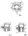
- FIG. 1 shows a pneumatic hammer A provided for two-armed operation, which is to be supplied by a pressure source D through a lateral connection.
- the Hammer A has a working cylinder 2 in the longitudinal axis, in which a Percussion piston 21, which cooperates with a tool 3, by one of the Pressure source D provided by prestressed pressure medium, if necessary Compressed air can be moved back and forth.
- a switching valve with a Switching valve body 5 can, as required, a device 1 for reversing be connected to the compressed air source D.
- the device 1 for reversing the pressurization of the percussion piston is spherical Control means 11 equipped, which alternatively or either at least a supply channel 41 directly the pressure source D with a working chamber 22 for an impact stroke or by means of an essentially to the working cylinder 2 axially parallel supply duct 42 the pressure source D with a working chamber 23 for connects the return stroke of the piston 21.
- FIG. 2 is according to section (A-A) of Fig. 1 an installation of a reversing device 1 with the spherical control means 11 and the supply channels 41 and 42 for to see the working chambers
- FIG. 3 is a central part of a device 1 for reversing one Pressurization of a working piston shown.
- a pressure source D is carried out by a drop in pressure in the direction of D2 spherical control means 11 to a sealing seat 12 to form a annular sealing line 14.
- Opposite is between a sealing seat 13 with an active surface 131 and the surface of the spherical control means 11 Gap for a flow of the pressure medium in direction D1 or for one Pressurization of a working chamber just located there.
- the Active surfaces 121, 131 of the sealing seats 12, 13 have the shape of an outer surface of a circular truncated cone or a spherical layer, the respectively from Control means 11 formed sealing line 14 in engagement between the upper and lower limit is arranged. So according to the invention when building a Reversing device a sealing line on the lower boundary 142 of the active surface 131 is provided in the sealing seat 13, so even with long-term wear and tear Shifting the sealing line to the upper limit 141 has a long service life the reversing device ensured.
- Fig. 4 shows a pneumatic hammer upper part A in longitudinal section.
- the device 1 for Umsteuem the pressurization of the percussion piston in the working cylinder 2 is in essentially designed as a disk-shaped component.
- One by one Switching valve body 5 released pressure medium provision takes place on a Front side of the device and is in through at least one recess Ax direction advanced in the reversing space.
- a spherical control means is between sealing seats, which are arranged essentially transversely to the axial direction, effective, the feed channel 41 to the working chamber 22 for the stroke of the piston by a deflection in the reversing device 1 in this Ax direction leaves.
- the pressure medium is provided for the return stroke in Reversing element 1 by means of a bore radially from a sealing seat in a circumferential recess 42 and through a feed channel to the relevant Chamber of Labor.
- This embodiment of the reversing device 1 is not only an efficient and improved pressurization of a percussion piston in the Given the stroke of the impact device, but it can also be done in a simple manner the reversing device or the disk-shaped component in each without interference Rotation position mounted and replaced if necessary.
- FIG. 5 shows a device for reversing the pressurization of a Percussion piston in a pneumatic hammer A, in which a control means 11th essentially by a screw-in part in the handle body at a distance between the sealing seats, which serve as supply channels 41 and 42 Chamber of Labor are continued.
- a pressure medium supply D in the Reversal space takes place transversely to the movement of the control means.
Landscapes
- Physics & Mathematics (AREA)
- Fluid Mechanics (AREA)
- Engineering & Computer Science (AREA)
- Mechanical Engineering (AREA)
- Percussive Tools And Related Accessories (AREA)
- Press Drives And Press Lines (AREA)
- Eye Examination Apparatus (AREA)
- Steering Control In Accordance With Driving Conditions (AREA)
- Supply Devices, Intensifiers, Converters, And Telemotors (AREA)
- Control Of Presses (AREA)
- Casting Or Compression Moulding Of Plastics Or The Like (AREA)
Abstract
Description
Alternativ kann auch vorgesehen sein, daß diese Umsteuereinrichtung zumindest teilweise durch den mit dem Arbeitszylinder verbundenen, dem Werkzeug gegenüberliegenden Teil des Schlaggerätes gebildet ist. Diese integrierte Ausführungsform der Umsteuereinrichtung , zum Beispiel im Griffteil eines Hammers, kann kostengünstig sein und bietet eine gegebenenfalls günstige undloder erforderliche Verkürzung der Baulänge des Schlaggerätes.
Es zeigen:
Claims (10)
- Einrichtung (1) zum Umsteuem der Druckbeaufschlagung eines in einem Gehäuse bzw. Arbeitszylinder (2) eines Schlaggerätes (A), insbesondere eines pneumatischen Hammers, hin- und herbewegbaren Schlagkolbens (21), welcher mit einem Werkzeug (3) zusammenwirkt, wobei die Arbeitskammem (22, 23) im Arbeitszylinder (2) durch ein Steuermittel (11) bzw. einem Ventilkörper mit zwei Dichtsitzen (12.13) über nachgeordnete Zuleitungskanäle (41, 42) abwechselnd mit einer Druckquelle verbindbar sind, dadurch gekennzeichnet, daß das Steuermittel (11) die Form einer Kugel aufweist.
- Einrichtung nach Anspruch 1, dadurch gekennzeichnet, daß die Wirkfläche (121,131) der Dichtsitze ( 12,13) die Form der Mantelfläche eines Kreiskegelstumpfes oder einer Kugelschichte aufweist und daß der Durchmesser der Dichtsitze (12,13) und jener des kugelförmigen Steuermittels (11) jeweils derart bemessen sind, daß die kreisförmige Dichtlinie (14) bzw. die dergleichen Berührungslinie des Steuermittels (11) im Dichtsitz (12,13) in einem Bereich mit einem Abstand von mindestens 0,02mal den Durchmesser des Steuermittels (11), zwischen in Axrichtung der oberen (141) und der unteren (142) Begrenzung der Wirkfläche (131) der Dichtsitze (12,13) ausbildbar ist.
- Einrichtung nach Anspruch 1 oder 2, dadurch gekennzeichnet, daß der mittlere Durchmesser der Dichtsitze ( 12,13) einen Wert von 0,86 bis 0,55mal, vorzugsweise 0,82 bis 0,68mal, den Durchmesser des kugelförmigen Steuermittels (11) aufweist.
- Einrichtung nach einem der Ansprüche 1 bis 3, dadurch gekennzeichnet, daß im geoffenten Zustand die Oberfläche des kugelförmigen Steuermittels (11) und die Wirkfläche der jeweiligen Dichtsitze im Bereich der Dichtlinie (14) einen Abstand von mindestens 0,011 bis höchstens 0,11, vorzugsweise von 0,04 bis 0,06mal den Durchmesser des Steuermittels (11) aufweist.
- Einrichtung nach einem der Ansprüche 1 bis 4, dadurch gekennzeichnet, daß das kugelförmige Steuermittel (11) ein Gewicht von weniger als 7,8 Gramm, vorzugsweise weniger als 4,9 Gramm, je Kubikzentimeter Kugelvolumen aufweist.
- Einrichtung nach einem der Ansprüche 1 bis 5, dadurch gekennzeichnet, daß das kugelförmige Steuermittel (11) aus Kunststoff gebildet ist.
- Einrichtung nach einem der Ansprüche 1 bis 6, dadurch gekennzeichnet, daß diese Umsteuereinrichtung (1) als eigenes Bauelement ausgeführt und in das Schlaggerät eingesetzt ist.
- Einrichtung nach einem der Ansprüche 1 bis 7, dadurch gekennzeichnet, daß die Umsteuereinrichtung (1) als ein im wesentlichen scheibenförmiges Bauelement, mit umfänglich einer den Zuleitungskanal (42) zur Arbeitskammer (23) für den Rückhub des Schlagkolbens (21) teilweise bildende Ausnehmung ausgeführt ist, wobei die Verbindungskanalteile zur Druckquelle (D) und zur Arbeitskammer (22) für den Schlaghub des Schlagkolbens (21) im wesentlichen jeweils in Axrichtung aus dem Bauelement (1) austreten.
- Einrichtung nach einem der Ansprüche 1 bis 6, dadurch gekennzeichnet, daß diese Umsteuereinrichtung (1) zumindest teilweise durch den mit dem Arbeitszylinder verbundenen, dem Werkzeug gegenüberliegenden Teils des Schlaggerätes gebildet ist.
- Einrichtung nach einem der Ansprüche 1 bis 9, dadurch gekennzeichnet, daß der Zuleitungskanal (42) zur Arbeitskammer (23) für den Rückhub des Schlagkolbens 21 integriert im Schalldämpfer des Schlaggerätes A geführt ist.
Priority Applications (1)
| Application Number | Priority Date | Filing Date | Title |
|---|---|---|---|
| AT98890168T ATE237428T1 (de) | 1997-06-13 | 1998-06-03 | Schlaggerät mit einer einrichtung zum umsteuern der druckbeaufschlagung des schlagkolbens |
Applications Claiming Priority (3)
| Application Number | Priority Date | Filing Date | Title |
|---|---|---|---|
| AT1030/97 | 1997-06-13 | ||
| AT0103097A AT407357B (de) | 1997-06-13 | 1997-06-13 | Einrichtung zum umsteuern der druckbeaufschlagung eines schlagkolbens |
| AT103097 | 1997-06-13 |
Publications (3)
| Publication Number | Publication Date |
|---|---|
| EP0885695A2 true EP0885695A2 (de) | 1998-12-23 |
| EP0885695A3 EP0885695A3 (de) | 2000-07-05 |
| EP0885695B1 EP0885695B1 (de) | 2003-04-16 |
Family
ID=3505156
Family Applications (1)
| Application Number | Title | Priority Date | Filing Date |
|---|---|---|---|
| EP98890168A Expired - Lifetime EP0885695B1 (de) | 1997-06-13 | 1998-06-03 | Schlaggerät mit einer Einrichtung zum Umsteuern der Druckbeaufschlagung des Schlagkolbens |
Country Status (4)
| Country | Link |
|---|---|
| EP (1) | EP0885695B1 (de) |
| AT (2) | AT407357B (de) |
| DE (1) | DE59807928D1 (de) |
| ES (1) | ES2201430T3 (de) |
Cited By (1)
| Publication number | Priority date | Publication date | Assignee | Title |
|---|---|---|---|---|
| AT522289A1 (de) * | 2019-03-28 | 2020-10-15 | Bbg Baugeraete Gmbh | Pneumatischer Grobhammer |
Family Cites Families (8)
| Publication number | Priority date | Publication date | Assignee | Title |
|---|---|---|---|---|
| DE165215C (de) * | ||||
| DE351939C (de) * | 1920-10-14 | 1922-04-19 | Edmond Leclercq | Drucklufthammer |
| DE429269C (de) * | 1922-12-06 | 1926-05-22 | Maschb Akt Ges H Flottmann & C | Pressluftwerkzeug mit flatterndem Steuerkoerper |
| AT118579B (de) * | 1929-08-03 | 1930-07-25 | Josef Kern | Hilfssteuerung für kolbengesteuerte Preßluftwerkzeuge. |
| JPS5899566A (ja) * | 1981-12-07 | 1983-06-13 | Saginomiya Seisakusho Inc | 二位置作動三方弁 |
| JPS58113670A (ja) * | 1981-12-25 | 1983-07-06 | Nippon Denso Co Ltd | 負圧制御弁 |
| AT392752B (de) * | 1984-01-05 | 1991-06-10 | Voest Alpine Stahl | Pneumatischer hammer |
| JPS6124880A (ja) * | 1984-07-10 | 1986-02-03 | Daihatsu Motor Co Ltd | 方向切換弁 |
-
1997
- 1997-06-13 AT AT0103097A patent/AT407357B/de not_active IP Right Cessation
-
1998
- 1998-06-03 DE DE59807928T patent/DE59807928D1/de not_active Expired - Fee Related
- 1998-06-03 ES ES98890168T patent/ES2201430T3/es not_active Expired - Lifetime
- 1998-06-03 EP EP98890168A patent/EP0885695B1/de not_active Expired - Lifetime
- 1998-06-03 AT AT98890168T patent/ATE237428T1/de not_active IP Right Cessation
Cited By (1)
| Publication number | Priority date | Publication date | Assignee | Title |
|---|---|---|---|---|
| AT522289A1 (de) * | 2019-03-28 | 2020-10-15 | Bbg Baugeraete Gmbh | Pneumatischer Grobhammer |
Also Published As
| Publication number | Publication date |
|---|---|
| AT407357B (de) | 2001-02-26 |
| EP0885695A3 (de) | 2000-07-05 |
| ES2201430T3 (es) | 2004-03-16 |
| DE59807928D1 (de) | 2003-05-22 |
| ATA103097A (de) | 2000-07-15 |
| EP0885695B1 (de) | 2003-04-16 |
| ATE237428T1 (de) | 2003-05-15 |
Similar Documents
| Publication | Publication Date | Title |
|---|---|---|
| EP0183093B1 (de) | Hydraulische Schlagvorrichtung | |
| EP2044333B9 (de) | Druckübersetzer mit doppelsitzventil | |
| EP2038553B1 (de) | Zylinder-kolbenanordnung für eine fluidpumpe oder einen fluidmotor | |
| DE3934124A1 (de) | Druckluftgetriebene pumpenanordnung | |
| DE4418972C2 (de) | Schwingungsdämpfer für Kraftfahrzeuge | |
| DE10058250A1 (de) | Doppelhubzylinder | |
| DE3347016C2 (de) | ||
| DE60309280T2 (de) | Integriertes Ringventil für einen Kompressorkolben | |
| EP0885695B1 (de) | Schlaggerät mit einer Einrichtung zum Umsteuern der Druckbeaufschlagung des Schlagkolbens | |
| EP1105667B1 (de) | Ventilschieber | |
| DE69612221T2 (de) | Pressluftmotor | |
| CH677806A5 (de) | ||
| DE2027395A1 (de) | Doppelt wirkender druckmittelbeaufschlagter Arbeitszylinder mit Endlagendämpfung | |
| DE2733508B2 (de) | Versenkbohrhammer | |
| DE2349296A1 (de) | Druckluft-schlagmaschine | |
| CH652805A5 (de) | Druckumsetzer mit mindestens drei oelhydraulisch angetriebenen kolben. | |
| DE3318297A1 (de) | Druckluftschlagvorrichtung | |
| DE69420713T2 (de) | Durch druckmittel angetriebene vorrichtung die eine lineare bewegung ausführt | |
| AT392752B (de) | Pneumatischer hammer | |
| DE1813712B2 (de) | Optisches Abtastsystem | |
| DE20119207U1 (de) | Pneumatische Brems- und Dämpfeinrichtung für bewegbare Möbelteile | |
| DE862562C (de) | Umsteuerung fuer Kolbenmaschinen | |
| DE19851444B4 (de) | Ausbauvorrichtung für die äußere, als Werkzeugabstützung dienende Führungsbuchse im Gehäuse eines Schlagwerks | |
| DE3541540C2 (de) | ||
| DE2945863A1 (de) | Antriebszylinder fuer fluidische steuerungen |
Legal Events
| Date | Code | Title | Description |
|---|---|---|---|
| PUAI | Public reference made under article 153(3) epc to a published international application that has entered the european phase |
Free format text: ORIGINAL CODE: 0009012 |
|
| AK | Designated contracting states |
Kind code of ref document: A2 Designated state(s): AT BE CH DE DK ES FI FR GB GR IT LI LU NL PT SE |
|
| AX | Request for extension of the european patent |
Free format text: AL;LT;LV;MK;RO;SI |
|
| RAP1 | Party data changed (applicant data changed or rights of an application transferred) |
Owner name: BOEHLER PNEUMATIK INTERNATIONAL GMBH & CO KG |
|
| PUAL | Search report despatched |
Free format text: ORIGINAL CODE: 0009013 |
|
| AK | Designated contracting states |
Kind code of ref document: A3 Designated state(s): AT BE CH CY DE DK ES FI FR GB GR IE IT LI LU MC NL PT SE |
|
| AX | Request for extension of the european patent |
Free format text: AL;LT;LV;MK;RO;SI |
|
| RIC1 | Information provided on ipc code assigned before grant |
Free format text: 7B 23Q 5/033 A, 7B 25D 9/14 B |
|
| 17P | Request for examination filed |
Effective date: 20000929 |
|
| AKX | Designation fees paid |
Free format text: AT BE CH DE DK ES FI FR GB GR IT LI LU NL PT SE |
|
| RAP1 | Party data changed (applicant data changed or rights of an application transferred) |
Owner name: BOEHLER BAUGERAETE GMBH & CO KG |
|
| RTI1 | Title (correction) |
Free format text: PERCUSSION APPARATUS WITH A DEVICE FOR REVERSING THE PRESSURE ON THE PISTON |
|
| GRAH | Despatch of communication of intention to grant a patent |
Free format text: ORIGINAL CODE: EPIDOS IGRA |
|
| RIN1 | Information on inventor provided before grant (corrected) |
Inventor name: HASEWEND, GERHARD Inventor name: GARGER, ERWIN Inventor name: AUER, ANTON |
|
| GRAH | Despatch of communication of intention to grant a patent |
Free format text: ORIGINAL CODE: EPIDOS IGRA |
|
| GRAA | (expected) grant |
Free format text: ORIGINAL CODE: 0009210 |
|
| AK | Designated contracting states |
Designated state(s): AT BE CH DE DK ES FI FR GB GR IT LI LU NL PT SE |
|
| PG25 | Lapsed in a contracting state [announced via postgrant information from national office to epo] |
Ref country code: NL Free format text: LAPSE BECAUSE OF FAILURE TO SUBMIT A TRANSLATION OF THE DESCRIPTION OR TO PAY THE FEE WITHIN THE PRESCRIBED TIME-LIMIT Effective date: 20030416 Ref country code: FI Free format text: LAPSE BECAUSE OF FAILURE TO SUBMIT A TRANSLATION OF THE DESCRIPTION OR TO PAY THE FEE WITHIN THE PRESCRIBED TIME-LIMIT Effective date: 20030416 |
|
| REG | Reference to a national code |
Ref country code: GB Ref legal event code: FG4D Free format text: NOT ENGLISH |
|
| REG | Reference to a national code |
Ref country code: CH Ref legal event code: EP |
|
| REF | Corresponds to: |
Ref document number: 59807928 Country of ref document: DE Date of ref document: 20030522 Kind code of ref document: P |
|
| PG25 | Lapsed in a contracting state [announced via postgrant information from national office to epo] |
Ref country code: LU Free format text: LAPSE BECAUSE OF NON-PAYMENT OF DUE FEES Effective date: 20030603 |
|
| GBT | Gb: translation of ep patent filed (gb section 77(6)(a)/1977) | ||
| PG25 | Lapsed in a contracting state [announced via postgrant information from national office to epo] |
Ref country code: BE Free format text: LAPSE BECAUSE OF NON-PAYMENT OF DUE FEES Effective date: 20030630 |
|
| REG | Reference to a national code |
Ref country code: CH Ref legal event code: NV Representative=s name: FREI PATENTANWALTSBUERO |
|
| PG25 | Lapsed in a contracting state [announced via postgrant information from national office to epo] |
Ref country code: PT Free format text: LAPSE BECAUSE OF FAILURE TO SUBMIT A TRANSLATION OF THE DESCRIPTION OR TO PAY THE FEE WITHIN THE PRESCRIBED TIME-LIMIT Effective date: 20030716 Ref country code: GR Free format text: LAPSE BECAUSE OF FAILURE TO SUBMIT A TRANSLATION OF THE DESCRIPTION OR TO PAY THE FEE WITHIN THE PRESCRIBED TIME-LIMIT Effective date: 20030716 Ref country code: DK Free format text: LAPSE BECAUSE OF FAILURE TO SUBMIT A TRANSLATION OF THE DESCRIPTION OR TO PAY THE FEE WITHIN THE PRESCRIBED TIME-LIMIT Effective date: 20030716 |
|
| REG | Reference to a national code |
Ref country code: SE Ref legal event code: TRGR |
|
| NLV1 | Nl: lapsed or annulled due to failure to fulfill the requirements of art. 29p and 29m of the patents act | ||
| ET | Fr: translation filed | ||
| BERE | Be: lapsed |
Owner name: *BOHLER BAUGERATE G.M.B.H. & CO. K.G. Effective date: 20030630 |
|
| PLBE | No opposition filed within time limit |
Free format text: ORIGINAL CODE: 0009261 |
|
| STAA | Information on the status of an ep patent application or granted ep patent |
Free format text: STATUS: NO OPPOSITION FILED WITHIN TIME LIMIT |
|
| REG | Reference to a national code |
Ref country code: ES Ref legal event code: FG2A Ref document number: 2201430 Country of ref document: ES Kind code of ref document: T3 |
|
| 26N | No opposition filed |
Effective date: 20040119 |
|
| REG | Reference to a national code |
Ref country code: GB Ref legal event code: 732E |
|
| REG | Reference to a national code |
Ref country code: FR Ref legal event code: TP |
|
| REG | Reference to a national code |
Ref country code: ES Ref legal event code: PC2A |
|
| PGFP | Annual fee paid to national office [announced via postgrant information from national office to epo] |
Ref country code: ES Payment date: 20080627 Year of fee payment: 11 Ref country code: CH Payment date: 20080613 Year of fee payment: 11 |
|
| PGFP | Annual fee paid to national office [announced via postgrant information from national office to epo] |
Ref country code: AT Payment date: 20080616 Year of fee payment: 11 |
|
| PGFP | Annual fee paid to national office [announced via postgrant information from national office to epo] |
Ref country code: IT Payment date: 20080624 Year of fee payment: 11 |
|
| PGFP | Annual fee paid to national office [announced via postgrant information from national office to epo] |
Ref country code: SE Payment date: 20080612 Year of fee payment: 11 Ref country code: DE Payment date: 20080620 Year of fee payment: 11 |
|
| PGFP | Annual fee paid to national office [announced via postgrant information from national office to epo] |
Ref country code: FR Payment date: 20080613 Year of fee payment: 11 |
|
| PGFP | Annual fee paid to national office [announced via postgrant information from national office to epo] |
Ref country code: GB Payment date: 20080620 Year of fee payment: 11 |
|
| REG | Reference to a national code |
Ref country code: CH Ref legal event code: PL |
|
| GBPC | Gb: european patent ceased through non-payment of renewal fee |
Effective date: 20090603 |
|
| REG | Reference to a national code |
Ref country code: FR Ref legal event code: ST Effective date: 20100226 |
|
| PG25 | Lapsed in a contracting state [announced via postgrant information from national office to epo] |
Ref country code: LI Free format text: LAPSE BECAUSE OF NON-PAYMENT OF DUE FEES Effective date: 20090630 Ref country code: FR Free format text: LAPSE BECAUSE OF NON-PAYMENT OF DUE FEES Effective date: 20090630 Ref country code: CH Free format text: LAPSE BECAUSE OF NON-PAYMENT OF DUE FEES Effective date: 20090630 |
|
| PG25 | Lapsed in a contracting state [announced via postgrant information from national office to epo] |
Ref country code: GB Free format text: LAPSE BECAUSE OF NON-PAYMENT OF DUE FEES Effective date: 20090603 |
|
| PG25 | Lapsed in a contracting state [announced via postgrant information from national office to epo] |
Ref country code: DE Free format text: LAPSE BECAUSE OF NON-PAYMENT OF DUE FEES Effective date: 20100101 Ref country code: AT Free format text: LAPSE BECAUSE OF NON-PAYMENT OF DUE FEES Effective date: 20090603 |
|
| REG | Reference to a national code |
Ref country code: ES Ref legal event code: FD2A Effective date: 20090604 |
|
| PG25 | Lapsed in a contracting state [announced via postgrant information from national office to epo] |
Ref country code: ES Free format text: LAPSE BECAUSE OF NON-PAYMENT OF DUE FEES Effective date: 20090604 |
|
| PG25 | Lapsed in a contracting state [announced via postgrant information from national office to epo] |
Ref country code: IT Free format text: LAPSE BECAUSE OF NON-PAYMENT OF DUE FEES Effective date: 20090603 |
|
| PG25 | Lapsed in a contracting state [announced via postgrant information from national office to epo] |
Ref country code: SE Free format text: LAPSE BECAUSE OF NON-PAYMENT OF DUE FEES Effective date: 20090604 |