EP0885703A1 - Procede de destruction par pression hydraulique de refoulement - Google Patents
Procede de destruction par pression hydraulique de refoulement Download PDFInfo
- Publication number
- EP0885703A1 EP0885703A1 EP96925129A EP96925129A EP0885703A1 EP 0885703 A1 EP0885703 A1 EP 0885703A1 EP 96925129 A EP96925129 A EP 96925129A EP 96925129 A EP96925129 A EP 96925129A EP 0885703 A1 EP0885703 A1 EP 0885703A1
- Authority
- EP
- European Patent Office
- Prior art keywords
- destroy
- electric discharge
- hydraulic pressure
- discharge hydraulic
- destroying
- Prior art date
- Legal status (The legal status is an assumption and is not a legal conclusion. Google has not performed a legal analysis and makes no representation as to the accuracy of the status listed.)
- Withdrawn
Links
Images






Classifications
-
- B—PERFORMING OPERATIONS; TRANSPORTING
- B28—WORKING CEMENT, CLAY, OR STONE
- B28D—WORKING STONE OR STONE-LIKE MATERIALS
- B28D1/00—Working stone or stone-like materials, e.g. brick, concrete or glass, not provided for elsewhere; Machines, devices, tools therefor
-
- E—FIXED CONSTRUCTIONS
- E21—EARTH OR ROCK DRILLING; MINING
- E21C—MINING OR QUARRYING
- E21C37/00—Other methods or devices for dislodging with or without loading
- E21C37/06—Other methods or devices for dislodging with or without loading by making use of hydraulic or pneumatic pressure in a borehole
-
- E—FIXED CONSTRUCTIONS
- E21—EARTH OR ROCK DRILLING; MINING
- E21C—MINING OR QUARRYING
- E21C37/00—Other methods or devices for dislodging with or without loading
- E21C37/18—Other methods or devices for dislodging with or without loading by electricity
Definitions
- the present invention relates to an electric discharge hydraulic pressure destroying method for destroying an object having one free surface, such as a rock bed in a tunnel or a housing land under development, a concrete structure, or an underwater rock bed or a concrete structure.
- an electric discharge hydraulic pressure destroying method which comprises discharging, in a very short time, electric energy stored in a capacitor and feeding it to a thin metal wire, and destroying a near-by object by an impulsive force produced by resulting sudden gasification of the thin metal wire itself and a surrounding destroying liquid.
- This electric discharge hydraulic pressure destroying method is not influenced by the ambient temperature or by the time elapsed after the installing and does not cause explosion unless a voltage is imposed; thus, the method is extremely safe and is capable of easily adjusting the destroying force and, therefore, is utilized for destroying concrete structures, such as decaying buildings.
- an object to which the electric discharge hydraulic pressure destroying method is applied is a concrete mass whose all sides are usually free surfaces, but the method has been rarely applied to an object having only one free surface, such as a rock bed.
- An object of the invention is to provide an electric discharge hydraulic pressure destroying method which is capable of more efficiently destroying an object having only one free surface.
- an electric discharge hydraulic pressure destroying method for destroying an object to be destroyed having only one free surface by using an electric discharge hydraulic pressure destroying tool which feeds electric energy stored in a capacitor to a thin metal wire in a very short time to utilize a shock force resulting from sudden gasification and volumetric expansion of the metal wire and a surrounding liquid comprising the steps of forming a pilot hole in said first free surface vertically of the latter to use the inner surface thereof as a second free surface, forming a destroy hole at one place in the first free surface in the periphery of this pilot hole, installing the electric discharge hydraulic pressure destroying tool in said destroy hole to destroy the object by electric discharge destruction to widen the destroy hole so as to enlarge the second free surface continuous with the pilot hole, forming a second destroy hole in the periphery of the pilot hole, destroying the object by electric discharge destruction effected by the electric discharge hydraulic pressure destroying tool, such procedure being repeated to widen the pilot hole.
- the invention is characterized in that ⁇ A > ⁇ B and DA ⁇ DB, where ⁇ A is the diameter of the pilot hole, DA is the depth of the pilot hole, ⁇ B is the diameter of the destroy hole and DB is the depth of the destroy hole.
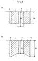
- setting the diameter ⁇ A of the pilot hole greater than the diameter ⁇ B of the destroy hole makes it possible to widen the direct destroy region to make effective use of the destroying force of the electric discharge hydraulic pressure destroying tool. Further, setting the depth DA of the pilot hole greater than or equal to the depth DB of the destroy hole enables the direct destroy region to reliably continue between the destroy hole and the pilot hole, so that the Portion of the object in the direct destroy region can be reliably hollowed, with lumps of material removed therefrom.
- another electric discharge hydraulic pressure destroying method for destroying an object to be destroyed having only one free surface by using an electric discharge hydraulic pressure destroying tool which feeds electric energy stored in a capacitor to a thin metal wire in a very short time to utilize a shock force resulting from sudden gasification and volumetric expansion of the metal wire and a surrounding liquid comprises the steps of forming a pilot hole in said free surface to use the inner surface thereof as a second free surface, forming a plurality of destroy holes around this pilot hole, installing an electric discharge hydraulic pressure destroying tool in each destroy hole, and feeding electric energy stored in the capacitor successively in circumferential order to the individual electric discharge hydraulic pressure destroying tools in the destroy holes, thereby destroying the object by electric discharge destruction.
- the invention is characterized in that the distance Y between adjacent destroy holes is defined by Y > L, where L is the width of direct destroy regions destroyed by the discharge hydraulic pressure destroying tools.
- the invention is characterized in that ⁇ A > ⁇ B and DA ⁇ DB, where ⁇ A is the diameter of the pilot hole, DA is the depth of the pilot hole, ⁇ B is the diameter of the destroy holes and DB is the depth of the destroy holes.
- setting the diameter ⁇ A of the pilot hole greater than the diameter ⁇ B of the destroy hole makes it possible to widen the direct destroy region to make effective use of the destroying force of the electric discharge hydraulic pressure destroying tool. Further, setting the depth DA of the pilot hole greater than or equal to the depth DB of the destroy hole enables the direct destroy region to reliably continue between the destroy hole and the pilot hole, so that the portion of the object in the, direct destroy region can be reliably hollowed, with lumps of material of the portion removed therefrom.
- An electric discharge hydraulic pressure destroying method for destroying an object to be destroyed having only one free surface by using a discharge hydraulic pressure destroying tool which feeds electric energy stored in a capacitor to a thin metal wire in a very short time to utilize a shock force resulting from sudden gasification and volumetric expansion of the metal wire and a surrounding liquid comprises the steps of drilling a pilot hole in the free surface to use the inner surface thereof as a second free surface, forming a plurality of destroy holes around this pilot hole, installing an electric discharge hydraulic pressure destroying tool in each of the destroy holes, and effecting electric discharge destruction by feeding electric energy stored in the capacitor simultaneously to the individual electric discharge hydraulic pressure destroying tools (4).
- the invention is characterized in that the distance Y between adjacent destroy holes is defined by Y ⁇ 2 ⁇ L , where L is the width of a direct destroy region destroyed by the electric discharge hydraulic pressure destroying tool.
- the direct destroy regions in adjacent destroy holes can be interconnected to make it possible to reliably hollow the object, with lumps of material of the destroyed portion removed therefrom, and to increase the volume to be hollowed.
- the invention is characterized in that ⁇ A > ⁇ B and DA ⁇ DB, where ⁇ A is the diameter of the pilot hole, DA is the depth of the pilot hole, ⁇ B is the diameter of the destroy hole and DB is the depth of the destroy hole.
- setting the diameter ⁇ A of the pilot hole greater than the diameter ⁇ B of the destroy hole makes it possible to widen the direct destroy region to make effective use of the destroying force of the electric discharge hydraulic pressure destroying tool. Further, setting the depth DA of the pilot hole greater than or equal to the depth DB of the destroy hole enables the direct destroy region to reliably continue between the destroy hole and the pilot hole, so that the portion of the object in the direct destroy region can be reliably hollowed, with lumps of material of the portion removed therefrom.
- the invention is characterized in that the intercentral distance X between the pilot hole and the destroy hole is in the range defined by X ⁇ ⁇ [( ⁇ A / 2) 2 + L 2 ] , where L is the width of the direct destroy region destroyed by the electric discharge hydraulic pressure destroying tool, and ⁇ A is the diameter of the pilot hole, and in that the distance L (cm) between direct destroy regions is in the range defined by
- the charging voltage required for a predetermined direct destroy region can be reliably supplied and the required direct destroy region can be reliably obtained.
- Another electric discharge hydraulic pressure destroying method for destroying an object to be destroyed having only one free surface by using an electric discharge hydraulic pressure destroying tool which feeds electric energy stored in a capacitor to a thin metal wire in a very short time to utilize a shock force resulting from sudden gasification and volumetric expansion of the metal wire and a surrounding liquid comprises the steps of forming inclined destroy holes at a plurality of places around a drilled region which defines the center of destruction for the free surface, the front ends of said inclined destroy holes being directed to said center in the drilled region, installing an electric discharge hydraulic pressure destroying tool in each inclined destroy hole, and effecting electric discharge destruction of the object by feeding electric energy from the capacitor simultaneously to the individual electric discharge hydraulic pressure destroying tools in a short time, thereby hollowing the drilled region to form a second free surface, forming a plurality of destroy holes in the first free surface around the second free surface, destroying the object by the electric discharge hydraulic pressure destroying tools installed in the respective destroy holes to further enlarge the second free surface, this operation being repeated to complete the electric discharge destruction of
- the invention is characterized in that the intercentral distance E between the openings of adjacent inclined destroy holes is in the range defined by E ⁇ 2 ⁇ L , where L is the width of the direct destroy region destroyed by the electric discharge hydraulic pressure destroying tool, and in that, of the adjoining inclined destroy holes, the distance between the front ends of the most greatly separated inclined destroy holes is set such that the direct destroy regions destroyed by two discharge hydraulic pressure destroying tools either contact or overlap each other, the direct destroy regions being interconnected at their bottoms to hollow the drilled region.
- the direct destroy regions can be interconnected between the front ends of the inclined destroy holes in the bottom, and even if the range is so wide that the direct destroy regions are not interconnected between the openings of the opposed inclined destroy holes, the drilled region can be circumferentially hollowed between the drilled regions to remove lumps of material of the hollowed portion from the object by interconnecting the direct destroy regions at their bottoms; thus, the second free surface can be formed in a wide range.
- the invention is characterized in that the width L (cm) of the direct destroy region is in the range defined by
- the charging voltage required to form a direct destroy region can be reliably supplied and the required direct destroy region can be reliably obtained.
- Another electric discharge hydraulic pressure destroying method for destroying an object to be destroyed having only one free surface by using a electric discharge hydraulic pressure destroying tool which feeds electric energy stored in a capacitor to a thin metal wire in a very short time to cause sudden gasification and volumetric expansion of the metal wire and a surrounding liquid comprises the steps of forming inclined destroy holes at a plurality of places, along inclined destroy surfaces extending outward from the innermost central portion of a pilot groove which is formed in the free surface and which defines the center of destruction, installing a electric discharge hydraulic pressure destroying tool in each of the destroy holes, and effecting electric discharge destruction of the object by feeding electric energy from the capacitor simultaneously to the individual electric discharge hydraulic pressure destroying tools in a short time, thereby hollowing out the pilot groove to form a second free surface, forming a next plurality of destroy holes around said pilot groove, and effecting electric discharge destruction of the object to enlarge the pilot groove by the electric discharge hydraulic pressure destroying tools installed in the respective destroy holes.
- inclined destroy holes are formed such that their front ends either intersect or close to each other along two inclined destroy surfaces extending outward from the center, and electric electric discharge hydraulic pressure destroying tools are installed in these inclined destroy holes to effect electric discharge destruction, thereby effectively hollowing out the pilot hole to form a second free surface, said second free surface being then utilized to effectively destroy the object.
- the invention is characterized in that said plurality of inclined s are formed at mutually opposed positions between two inclined destroy surfaces, the front ends of said inclined destroy holes reaching the intersecting line between said two inclined destroy surfaces, in that the intercentral distance XA 1 between the openings of adjacent inclined destroy holes on a same inclined destroy surface and the intercentral distance XA 2 between the front ends of inclined destroy holes are in the range defined by XA 1 ⁇ 2 ⁇ L and XA 2 ⁇ 2 ⁇ L , where L is the width of the direct destroy region destroyed by the electric discharge hydraulic pressure destroying tool, and in that the intercentral distance YA 2 between the front ends of adjacent inclined destroy holes between the two destroy surfaces is in the range defined by YA 2 ⁇ 2 ⁇ L .
- the pilot groove can be subjected to electric discharge destruction for a width range which is greater than that of the direct destroy region, whereby the object to be destroyed can be reliably hollowed, with lumps of material of the hollowed portion removed from the bottom.
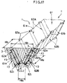
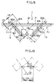
- the invention is characterized in that the inclined destroy holes are formed at mutually opposed positions along inclined destroy surfaces, in that the intercentral distance XB 1 between the openings of inclined destroy holes on a same destroy surface and the intercentral distance XB 2 between the front ends of the inclined destroy holes are in the range defined by XB 1 ⁇ 2 ⁇ L and XB 2 ⁇ 2 ⁇ L , where L is the width of the direct destroy region destroyed by the electric discharge hydraulic pressure destroying tool, and in that the intercentral distance YB 2 between the front ends of opposed inclined destroy holes is in the range defined by YB 2 ⁇ 2 ⁇ L cos (90° - ⁇ ) , where ⁇ is the angle of inclination of the inclined destroy hole with respect to the first free surface.
- the opening of the pilot groove can be subjected to electric discharge destruction for a width range which is greater than that of the direct destroy region, whereby the object to be destroyed can be reliably hollowed, with lumps of material of the hollowed portion removed from the bottom.
- the invention is characterized in that the width L (cm) of the direct destroy region is in the range defined by
- the charging voltage required to form a direct destroy region can be reliably supplied and the required direct destroy region can be reliably obtained.
- an electric discharge probe 3 which is a electric discharge hydraulic pressure destroying tool installed in a destroy hole 2 formed in an object to be destroyed 1, comprises a destroy container 5 made of synthetic rubber or waterproofed paper filled with a destroying liquid 4 such as water, a pair of electrode rods 7 extending through the top plate 5a of the destroy container 5 into the destroying liquid 4 and held mutually parallel by spacers 6, and a thin metal wire 8 connected between the front ends of the electrode bars 7.
- an energy supply circuit 10 having a capacitor 10a of large capacity disposed away from the object 1 is connected to said electrode bars 7 by a lead wire 9 having an electric discharge switch 9a.
- the energy supply circuit 10 is provided with a dc high voltage power source 10b for charging the capacitor 10a with electric energy.
- the capacitor 10a and the dc high voltage power source 10b are interconnected by a connecting wire 10d, with a charging switch 10c interposed in said connecting wire 10d.
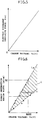
- the relation between charging voltage Vc for the capacitor 10a of the energy supply circuit 10 and electric discharge shock force F of the electric discharge probe 3 is proportional as shown in the graph of Fig. 5 indicating the F-Vc characteristic.
- the width (average width) L of a direct destroy region 13 destroyed by the electric discharge probe 3 is such that, as shown in Fig. 4, the width Li of an inner direct destroy region 13b and the width La of a surface direct destroy region 13a differ from each other.
- the relation between the electric discharge shock force F and the width Li, La of the direct destroy region 13, as shown in Fig. 6 and by an expression 1 ⁇ is derived as a proportional relation between the charging voltage Vc (volt) and the width L (cm) of the direct destroy region 13.
- the surface direct destroy region La corresponds to
- the inner direct destroy region Li corresponds to
- the object 1 to be destroyed by this method is one having only one free surface F1, such as a rock bed, concrete foundation, or concrete floor.
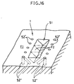
- Destroy holes 12 -1 - 12 -5 are formed in advance around the pilot hole 11 and electric discharge probes 3 are loaded therein. And a high voltage is successively circumferentially applied starting with the capacitor 10a to the electric discharge probes 3 of the destroy holes 12 -1 - 12 -5 to effect electric discharge destruction.
- an object to be destroyed can be effectively progressively destroyed by utilizing the first free surface F1 and the second free surface F2 which is formed by the pilot hole 11; the object 1 can be further effectively destroyed by utilizing the second free surface F2 which is progressively enlarged by the second and the following destructions and by means of the electric discharge probes 3 loaded in the subsequent destroy holes 12 -2 -12 -5 .
- the continuous destruction provides a high operating efficiency and the destroy operation can proceed with an operator comprehending the circumstances under which the operation is going on.
- Destroy holes 22 -1 - 22 -4 are formed in advance around a pilot hole 21 and electric discharge probes 3 are loaded therein and a high voltage is applied from the capacitor 10a simultaneously to each of the electric discharge probes 3 in the destroy holes 22 -1 - 22 -4 .
- the distance Y between the adjacent destroy holes 22 -1 - 22 -4 is less than twice the width L of the direct destroy regions 23 -1 - 23 -4 ;
- Two concrete samples measuring 1 m ⁇ 1 m ⁇ 0.3 m were each formed with a pilot hole 31 having a diameter ⁇ A of 4 cm and a depth DA of 20 cm, and destroy holes 32 having a diameter ⁇ B of 1.3 cm and a depth DB of 15 cm, formed at 6 places at equal intervals Y of 15 cm, separated for a distance X of 15 cm from the center of the pilot hole 31.
- an electric discharge probe 3 was loaded in each destroy hole 32, and successive and simultaneous destruction by electric discharge were effected at a charge voltage Vc of 4,000 V. Thereby, a volume of about 3,000 cm 3 could be destroyed.
- An object to be destroyed such as a rock bed, concrete foundation, or concrete floor, has a single free surface F1, as in the first through third embodiments.
- the inner surface of the pilot hole is not used as the second free surface and instead the substantially conical destroy surface destroyed by electric discharge probes 3 loaded in a plurality of s is used as the second free surface F2.
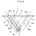
- An object to be destroyed 1 such as a rock bed, concrete foundation, or concrete floor, has a single free surface F1.
- the second free surface F2 is formed by substantially conically hollowing the object 1.
- the second free surface F2 is formed by hollowing out a fifth triangular pilot groove 51.
- the pilot groove is formed by the electric discharge probes 3 in the destroy holes formed in a zigzag pattern.
- destroy holes are formed in opposed posttions to form a pilot groove 61.
- pilot grooves 51 and 61 have been shown straight; however, they may be curved.
Landscapes
- Engineering & Computer Science (AREA)
- Mining & Mineral Resources (AREA)
- Life Sciences & Earth Sciences (AREA)
- General Life Sciences & Earth Sciences (AREA)
- Geochemistry & Mineralogy (AREA)
- Geology (AREA)
- Mechanical Engineering (AREA)
- Drilling And Exploitation, And Mining Machines And Methods (AREA)
- Perforating, Stamping-Out Or Severing By Means Other Than Cutting (AREA)
Applications Claiming Priority (7)
| Application Number | Priority Date | Filing Date | Title |
|---|---|---|---|
| JP07194412A JP3103020B2 (ja) | 1995-07-31 | 1995-07-31 | 放電液圧破壊工法 |
| JP194413/95 | 1995-07-31 | ||
| JP07194413A JP3103021B2 (ja) | 1995-07-31 | 1995-07-31 | 放電液圧破壊工法 |
| JP19441195A JPH0938951A (ja) | 1995-07-31 | 1995-07-31 | 放電液圧破壊工法 |
| JP194412/95 | 1995-07-31 | ||
| JP194411/95 | 1995-07-31 | ||
| PCT/JP1996/002140 WO1997004934A1 (fr) | 1995-07-31 | 1996-07-29 | Procede de destruction par pression hydraulique de refoulement |
Publications (2)
| Publication Number | Publication Date |
|---|---|
| EP0885703A1 true EP0885703A1 (fr) | 1998-12-23 |
| EP0885703A4 EP0885703A4 (fr) | 2000-01-12 |
Family
ID=27326932
Family Applications (1)
| Application Number | Title | Priority Date | Filing Date |
|---|---|---|---|
| EP96925129A Withdrawn EP0885703A4 (fr) | 1995-07-31 | 1996-07-29 | Procede de destruction par pression hydraulique de refoulement |
Country Status (5)
| Country | Link |
|---|---|
| EP (1) | EP0885703A4 (fr) |
| KR (1) | KR19990029023A (fr) |
| CN (1) | CN1075430C (fr) |
| RU (1) | RU2139990C1 (fr) |
| WO (1) | WO1997004934A1 (fr) |
Families Citing this family (2)
| Publication number | Priority date | Publication date | Assignee | Title |
|---|---|---|---|---|
| CN112177626B (zh) * | 2020-08-25 | 2021-07-23 | 中国矿业大学 | 一种电极定向冲击作业巷道掘进方法 |
| CN112556523A (zh) * | 2020-11-23 | 2021-03-26 | 浙江科技学院 | 一种双面对称式电爆聚能破岩设计方法 |
Family Cites Families (6)
| Publication number | Priority date | Publication date | Assignee | Title |
|---|---|---|---|---|
| US4479680A (en) * | 1980-04-11 | 1984-10-30 | Wesley Richard H | Method and apparatus for electrohydraulic fracturing of rock and the like |
| SU1391231A1 (ru) * | 1986-05-13 | 1995-02-20 | Проектно-конструкторское бюро электрогидравлики АН УССР | Установка для разрушения монолитных образований |
| CN86104470A (zh) * | 1986-06-27 | 1988-01-06 | Ceee公司 | 脉冲电能发射分裂物质的方法和设备 |
| JPH07145698A (ja) * | 1993-09-28 | 1995-06-06 | Hitachi Zosen Corp | 被破壊物の破壊装置および破壊方法 |
| US5425570A (en) * | 1994-01-21 | 1995-06-20 | Maxwell Laboratories, Inc. | Method and apparatus for plasma blasting |
| JP3538225B2 (ja) * | 1994-07-29 | 2004-06-14 | 電気興業株式会社 | 熱プラズマを用いた塊状半導体材の破砕方法とその装置 |
-
1996
- 1996-07-29 KR KR1019980700326A patent/KR19990029023A/ko not_active Ceased
- 1996-07-29 CN CN96195794A patent/CN1075430C/zh not_active Expired - Fee Related
- 1996-07-29 RU RU98103872A patent/RU2139990C1/ru not_active IP Right Cessation
- 1996-07-29 WO PCT/JP1996/002140 patent/WO1997004934A1/fr not_active Ceased
- 1996-07-29 EP EP96925129A patent/EP0885703A4/fr not_active Withdrawn
Non-Patent Citations (2)
| Title |
|---|
| No further relevant documents disclosed * |
| See also references of WO9704934A1 * |
Also Published As
| Publication number | Publication date |
|---|---|
| EP0885703A4 (fr) | 2000-01-12 |
| RU2139990C1 (ru) | 1999-10-20 |
| CN1075430C (zh) | 2001-11-28 |
| CN1191504A (zh) | 1998-08-26 |
| WO1997004934A1 (fr) | 1997-02-13 |
| KR19990029023A (ko) | 1999-04-15 |
Similar Documents
| Publication | Publication Date | Title |
|---|---|---|
| KR100316161B1 (ko) | 에어튜브를 이용한 암반발파 방법 | |
| EP0692611B1 (fr) | Procédé d'excavation d'un front de travail | |
| US9010458B2 (en) | Pressure pulse fracturing system | |
| US20190177944A1 (en) | In-situ Piling and Anchor Shaping using Plasma Blasting | |
| AU2005277008B2 (en) | Pulsed electric rock drilling, fracturing, and crushing methods and apparatus | |
| KR100358780B1 (ko) | 에어튜브를 이용한 진동 및 폭음제어 터널발파방법 | |
| CN112044569B (zh) | 一种组合式多电极高压脉冲放电碎裂硬岩装置及破裂方法 | |
| EP0885703A1 (fr) | Procede de destruction par pression hydraulique de refoulement | |
| US11774220B2 (en) | Annular shaped-charge housing for blasting and method of using the same | |
| SU946409A3 (ru) | Способ забивки нижних концов шпунтин в грунт основани при возведении шпунтовой стенки | |
| KR19990002665A (ko) | 인장파괴를 이용한 암반절단방법 | |
| JP4167235B2 (ja) | 横坑の掘削方法 | |
| KR100317825B1 (ko) | 미진동 암반파쇄방법 | |
| JPH11117283A (ja) | 発破方法 | |
| JPH0938953A (ja) | 放電液圧破壊工法 | |
| AU2013204846B2 (en) | Pulsed Electric Rock Drilling, Fracturing, and Crushing Methods and Apparatus | |
| JPH0938952A (ja) | 放電液圧破壊工法 | |
| KR100426965B1 (ko) | 화약류가 장입되는 카트리지 및 그를 이용한 발파 방법 | |
| JPS6286228A (ja) | ケ−シングの圧入方法および延長用ケ−シング | |
| RU2065022C1 (ru) | Буровая коронка для ударного бурения | |
| SU901517A1 (ru) | Способ направленного выброса вечномерзлых пород | |
| CN112302673B (zh) | 采用瞬时胀裂器掘进巷道的方法 | |
| JPH10306679A (ja) | 電気破砕装置及びその方法 | |
| JP4202331B2 (ja) | 横坑の掘削方法 | |
| JP3192929B2 (ja) | 放電液圧破壊工法 |
Legal Events
| Date | Code | Title | Description |
|---|---|---|---|
| PUAI | Public reference made under article 153(3) epc to a published international application that has entered the european phase |
Free format text: ORIGINAL CODE: 0009012 |
|
| 17P | Request for examination filed |
Effective date: 19980302 |
|
| AK | Designated contracting states |
Kind code of ref document: A1 Designated state(s): CH DE FR GB LI |
|
| A4 | Supplementary search report drawn up and despatched |
Effective date: 19991125 |
|
| AK | Designated contracting states |
Kind code of ref document: A4 Designated state(s): CH DE FR GB LI |
|
| 17Q | First examination report despatched |
Effective date: 20020404 |
|
| STAA | Information on the status of an ep patent application or granted ep patent |
Free format text: STATUS: THE APPLICATION HAS BEEN WITHDRAWN |
|
| 18W | Application withdrawn |
Withdrawal date: 20020628 |