EP0885712B1 - Verteilerweiche für eine kunststoff-verarbeitende Anlage - Google Patents
Verteilerweiche für eine kunststoff-verarbeitende Anlage Download PDFInfo
- Publication number
- EP0885712B1 EP0885712B1 EP98105462A EP98105462A EP0885712B1 EP 0885712 B1 EP0885712 B1 EP 0885712B1 EP 98105462 A EP98105462 A EP 98105462A EP 98105462 A EP98105462 A EP 98105462A EP 0885712 B1 EP0885712 B1 EP 0885712B1
- Authority
- EP
- European Patent Office
- Prior art keywords
- channel
- channels
- control part
- housing
- connection
- Prior art date
- Legal status (The legal status is an assumption and is not a legal conclusion. Google has not performed a legal analysis and makes no representation as to the accuracy of the status listed.)
- Expired - Lifetime
Links
- 239000004033 plastic Substances 0.000 title description 21
- 229920003023 plastic Polymers 0.000 title description 21
- 229920001169 thermoplastic Polymers 0.000 claims abstract description 4
- 239000004416 thermosoftening plastic Substances 0.000 claims abstract description 4
- 229920002994 synthetic fiber Polymers 0.000 claims 3
- 238000013022 venting Methods 0.000 claims 1
- 239000000806 elastomer Substances 0.000 abstract description 2
- 229920001971 elastomer Polymers 0.000 abstract description 2
- 239000000463 material Substances 0.000 description 17
- 238000009423 ventilation Methods 0.000 description 5
- 238000001125 extrusion Methods 0.000 description 3
- 239000000155 melt Substances 0.000 description 3
- 238000004519 manufacturing process Methods 0.000 description 2
- 238000004140 cleaning Methods 0.000 description 1
- 238000010276 construction Methods 0.000 description 1
- 238000001914 filtration Methods 0.000 description 1
- 238000001746 injection moulding Methods 0.000 description 1
- 238000012423 maintenance Methods 0.000 description 1
- 238000005065 mining Methods 0.000 description 1
- 239000000203 mixture Substances 0.000 description 1
- 229920000642 polymer Polymers 0.000 description 1
- 239000002861 polymer material Substances 0.000 description 1
- 239000004800 polyvinyl chloride Substances 0.000 description 1
- 229920000915 polyvinyl chloride Polymers 0.000 description 1
- 239000007921 spray Substances 0.000 description 1
Images


Classifications
-
- B—PERFORMING OPERATIONS; TRANSPORTING
- B29—WORKING OF PLASTICS; WORKING OF SUBSTANCES IN A PLASTIC STATE IN GENERAL
- B29C—SHAPING OR JOINING OF PLASTICS; SHAPING OF MATERIAL IN A PLASTIC STATE, NOT OTHERWISE PROVIDED FOR; AFTER-TREATMENT OF THE SHAPED PRODUCTS, e.g. REPAIRING
- B29C48/00—Extrusion moulding, i.e. expressing the moulding material through a die or nozzle which imparts the desired form; Apparatus therefor
- B29C48/25—Component parts, details or accessories; Auxiliary operations
- B29C48/36—Means for plasticising or homogenising the moulding material or forcing it through the nozzle or die
- B29C48/50—Details of extruders
- B29C48/695—Flow dividers, e.g. breaker plates
-
- B—PERFORMING OPERATIONS; TRANSPORTING
- B29—WORKING OF PLASTICS; WORKING OF SUBSTANCES IN A PLASTIC STATE IN GENERAL
- B29C—SHAPING OR JOINING OF PLASTICS; SHAPING OF MATERIAL IN A PLASTIC STATE, NOT OTHERWISE PROVIDED FOR; AFTER-TREATMENT OF THE SHAPED PRODUCTS, e.g. REPAIRING
- B29C48/00—Extrusion moulding, i.e. expressing the moulding material through a die or nozzle which imparts the desired form; Apparatus therefor
- B29C48/25—Component parts, details or accessories; Auxiliary operations
- B29C48/36—Means for plasticising or homogenising the moulding material or forcing it through the nozzle or die
- B29C48/50—Details of extruders
- B29C48/69—Filters or screens for the moulding material
- B29C48/691—Arrangements for replacing filters, e.g. with two parallel filters for alternate use
-
- B—PERFORMING OPERATIONS; TRANSPORTING
- B29—WORKING OF PLASTICS; WORKING OF SUBSTANCES IN A PLASTIC STATE IN GENERAL
- B29C—SHAPING OR JOINING OF PLASTICS; SHAPING OF MATERIAL IN A PLASTIC STATE, NOT OTHERWISE PROVIDED FOR; AFTER-TREATMENT OF THE SHAPED PRODUCTS, e.g. REPAIRING
- B29C48/00—Extrusion moulding, i.e. expressing the moulding material through a die or nozzle which imparts the desired form; Apparatus therefor
- B29C48/03—Extrusion moulding, i.e. expressing the moulding material through a die or nozzle which imparts the desired form; Apparatus therefor characterised by the shape of the extruded material at extrusion
Definitions
- the invention relates to a distribution switch according to the preamble of claim 1.
- Such a distribution switch is from the generic DE 41 30 002 C1 known.
- the known distribution switch it advantageously possible to choose one of two outlet channels to connect the housing to the inlet duct, so that in a plastic processing system, for example material conveyed from an extruder into the distribution switch and from there can optionally be distributed to one of two nozzles, so that optionally one of two downstream extrusion devices or injection molding machines can be operated.
- DE 34 11 669 A1 describes a filter system for the continuous filtering of a polymer stream, this filter system working with a rotatable valve pin.
- This rotatable valve pin has two serious disadvantages. Firstly, the construction according to DE 34 11 669 - as can be seen most clearly from the illustration in FIG. 4 - has dead spaces for the flowing polymer material, so that this arrangement is e.g. B. cannot be used at all in the processing of polyvinyl chloride. Special check valves are inevitably required, as are clearly shown in FIG. 1 of DE 34 11 669.
- a distribution switch is from the generic WO 96/29186 for a plastics processing plant, in which three through channels are provided, namely one middle, fork-shaped through-channel, which is the inlet channel can connect with two outlet channels and two adjacent, simple passageways that either one or connect the other outlet duct to the inlet duct can.
- a connection such that two adjacent through-channels with its end facing the inlet duct at the same time can communicate with the inlet duct is not provided so that, for example, pre-ventilation does not take place can.
- the present invention is therefore based on the object to improve the generic distribution switch, that optionally not only one of the two downstream Facilities can be supplied with material, but alternatively also both downstream facilities and that it is possible, the newly used passage channel to vent and before starting full production already to be filled with plastic.
- the through channels optionally one, several or all systems Connect to the inlet channel or exclude it from the melt flow can.
- the control part can be used as a rotating disc, movable Plate or the like be designed.
- the control part can advantageously be used as cylindrical bolt movably mounted in its longitudinal direction be designed: the round cross-section of such Bolzens ensures a reliable seal against the surrounding housing and it can be of considerable length be made available, the arrangement of the desired Through channels easily possible. Possibly. can the overall length of the bolt even the housing dimensions surpass so that a variety of different configurations through channels can be provided.
- control unit In a so-called “start-up position", the control unit can also be used a special "start channel” in connection with the inlet channel stand.
- start channel When commissioning the entire system, if fresh The melt can get into the distribution switch Material can be discharged through the start-up channel without being in a downstream system to arrive because this first material is not usable.
- the approach channel can be accessed directly through the Lead the control unit outside or as a special channel in the housing be designed, not like the other outlet channels to a downstream system leads, but outdoors.
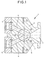
- a distribution switch is generally designated 1, the has a housing 2 which comprises an inlet duct 3.
- the distribution switch 1 can be provided in a system, for example be processed in the thermoplastic is, this heated and liquefied plastic from a Extruder enters the inlet channel 3.
- the housing 2 has two outlet channels 4, which become adapter pieces 5 lead, for example nozzles on the adapter pieces 5 an extrusion device can be connected.
- Control part 6 arranged, which as a cylindrical bolt is designed and has a plurality of through channels, wherein 1 shows a Y-shaped forked passage 7 is.
- the connected system components such as extruders on the one hand and spray nozzles on the other hand, are mentioned purely by way of example, the distribution switch 1 in also very different designed systems for processing thermoplastics or elastomers can be used.
- the distribution switch 1 in also very different designed systems for processing thermoplastics or elastomers can be used.
- Just as exemplary are just two downstream system components provided and therefore only three through channels in the control section.
- the arrangement of the distribution switch 1 according to FIG. 1 the normal position represents in the two extrusion devices equally be loaded with plastic material.
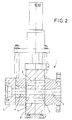
- the configuration of the control part 6 is elongated Bolt recognizable, the bifurcating through-channel 7 designed as the middle of a total of three through channels is. There is one above and one below the through channel 7 Through channel 8 arranged, both at the appropriate Position of the control part 6 a connection from the inlet duct 3rd to create only one of the two outlet channels 4 and accordingly bent or angled by the Control part 6 run, as can be seen in particular from FIG. 5 is.
- FIG. 3 shows a different position in a representation similar to FIG. 2 of the control part 6:
- the bolt is compared to FIG. 2 moved below, so that the upper through channel 8 Connection between the inlet duct 3 and one of the two Exhaust channels 4 creates while both the middle through channel 7 and the lower through channel 8 are not included Plastic material from the inlet channel 3 are loaded.
- In this Position is the material flow to the second outlet channel 4 interrupted so that the tool is changed here, the nozzle cleaned or similar work can be carried out.
- FIGS. 5 and 6 In FIG Distribution switch 1 shown in plan view, with a section through the control part 6 shows a through channel 8, which is not communicates with the upper outlet duct 4.
- FIG. 6 shows the side view of FIG. 5, with the control part 6 is not cut. Because of the folded down around the hinge 12 Cover is the now exposed outlet opening of the Through channel 8 recognizable.
- a Approach channel provided in the control part 6 or in the housing 2 due to the unusable first material during commissioning the system can be discharged without entering one of the plastic processing plants.
Landscapes
- Engineering & Computer Science (AREA)
- Mechanical Engineering (AREA)
- Extrusion Moulding Of Plastics Or The Like (AREA)
- Lining Or Joining Of Plastics Or The Like (AREA)
- Catching Or Destruction (AREA)
- Debarking, Splitting, And Disintegration Of Timber (AREA)
- Harvester Elements (AREA)
Description
Zwangsläufig sind auch spezielle Rückschlagventile erforderlich, wie sie deutlich in Fig. 1 der DE 34 11 669 dargestellt sind.
Eine derartige Ausgestaltung ist beispielsweise möglich, in dem die beiden Durchgangskanäle an ihren zum Einlaßkanal gerichteten Enden einen Abstand zueinander aufweisen, der geringer ist als die Querschnittsabmessung des Einlaßkanals an seinem dem Steuerteil benachbarten Ende. Bei einem größeren Abstand der eigentlichen Durchgangskanäle zueinander können Verbindungsbohrungen, Nuten o. dgl. vorgesehen sein, die den gleichzeitigen Schmelzfluß vom Einlaßkanal zu zwei Durchgangskanälen ermöglichen.
Zu diesem Zweck weist das Gehäuse Deckel auf, die entfernt oder geöffnet werden können, so daß der Zugang zu den außer Betrieb befindlichen Durchgangskanälen ermöglicht wird und diese gereinigt werden können.
Diese Deckel können vorteilhaft auch dann vorgesehen sein, wenn eine unterbrechungsfreie Produktionsweise der nachgeschalteten Anlagen nicht vorgesehen ist, da sie die Wartung und Reinigung des Steuerteils erleichtern.
Die Luft in diesem Durchgangskanal wird verdrängt und kann durch die Entlüftungsnut entweichen, bis der Durchgangskanal völlig von Luft befreit ist und ausschließlich mit frischem, verwendbaren Kunststoffmaterial befüllt ist.
- Fig. 1
- einen Horizontalschnitt durch eine Verteilerweiche,
- Fig. 2
- einen Vertikalschnitt durch die Weiche von Fig. 1,
- Fig. 3
- einen Vertikalschnitt ähnlich Fig. 2, wobei sich das Steuerteil in einer anderen Stellung befindet,
- Fig. 4
- einen Vertikalschnitt ähnlich Fig. 2 und 3, jedoch in einer dritten Stellung des Steuerteiles,
- Fig. 5
- eine Draufsicht auf die Verteilerweiche mit einem Querschnitt durch das Steuerteil, und
- Fig. 6
- eine Seitenansicht auf die Verteilerweiche.
Claims (6)
- Verteilerweiche zum Verarbeiten von thermoplastischen und elastomeren Kunststoffen, mit einem Gehäuse, und mit einem im Gehäuse quer zur Förderrichtung des in einem Verbindungskanal fließenden Kunststoffes verschiebbaren und gegenüber dem Gehäuse abgedichteten Steuerteil (6), der mehrere in seiner Bewegungsrichtung aufeinanderfolgend angeordnete Durchgangskanäle aufweist, die das Steuerteil (6) ganz durchqueren, wobei das Gehäuse als Verbindungskanal einen Einlaßkanal (3) und wenigstens zwei Auslaßkanäle (4) für den Kunststoff aufweist, die in Abhängigkeit von der Stellung des Steuerteils (6) in Verbindung mit dem Einlaßkanal (3) und einem der Auslaßkanäle (4) bringbar angeordnet sind, wobei wenigstens drei Durchgangskanäle (7, 8) vorgesehen sind, von denen zwei Durchgangskanäle (8) jeweils eine Verbindung vom Einlaßkanal (3) zu nur einem Auslaßkanal (4) schaffen und von denen der dritte Durchgangskanal (7) eine Verbindung zu wenigstens zwei Auslaßkanälen (4) schafft, dadurch gekennzeichnet, daß das Steuerteil (6) in eine Stellung bringbar ist, in der zwei benachbarte Durchgangskanäle (7 und 8) mit ihren zum Einlaßkanal (3) gerichteten Enden gleichzeitig mit dem Einlaßkanal (3) in Verbindung stehen und daß eine Entlüftungsnut (10) im Steuerteil (6) vorgesehen ist, die in der Stellung des Steuerteiles (6), in der zwei Durchgangskanäle (7, 8) mit dem Einlaßkanal (3) in Verbindung stehen, von wenigstens einem der Durchgangskanäle (7, 8) eine Verbindung zur Gehäuseaußenseite schafft.
- Verteilerweiche nach Anspruch 1, dadurch gekennzeichnet, daß der dritte Durchgangskanal (7) zwischen den beiden anderen Durchgangskanälen (8) angeordnet ist.
- Verteilerweiche nach Anspruch 1 oder 2, dadurch gekennzeichnet, daß der dritte Durchgangskanal (7) eine Verbindung zu sämtlichen Auslaßkanälen (4) schafft.
- Verteilerweiche nach einem der vorhergehenden Ansprüche, dadurch gekennzeichnet, daß das Steuerteil (6) als zylindrischer Bolzen ausgestaltet und in seiner Längsrichtung beweglich gelagert ist.
- Verteilerweiche nach einem der vorhergehenden Ansprüche, dadurch gekennzeichnet, daß im Steuerteil (6) ein zusätzlicher Kanal vorgesehen ist, der ins Freie führt oder zu einem im Gehäuse vorgesehenen Anfahrkanal, der eine Verbindung zur Gehäuseaußenseite schafft.
- Verteilerweiche nach einem der vorhergehenden Ansprüche, dadurch gekennzeichnet, daß am Gehäuse (2) lösbare Deckel (11) vorgesehen sind, die den Zugang zu jeweils einem Durchgangskanal freigeben, der von dem Einlaßkanal (3) getrennt ist.
Applications Claiming Priority (2)
| Application Number | Priority Date | Filing Date | Title |
|---|---|---|---|
| DE19726463A DE19726463A1 (de) | 1997-06-21 | 1997-06-21 | Verteilerweiche für eine kunststoffverarbeitende Anlage |
| DE19726463 | 1997-06-21 |
Publications (2)
| Publication Number | Publication Date |
|---|---|
| EP0885712A1 EP0885712A1 (de) | 1998-12-23 |
| EP0885712B1 true EP0885712B1 (de) | 2001-01-03 |
Family
ID=7833291
Family Applications (1)
| Application Number | Title | Priority Date | Filing Date |
|---|---|---|---|
| EP98105462A Expired - Lifetime EP0885712B1 (de) | 1997-06-21 | 1998-03-26 | Verteilerweiche für eine kunststoff-verarbeitende Anlage |
Country Status (3)
| Country | Link |
|---|---|
| EP (1) | EP0885712B1 (de) |
| AT (1) | ATE198441T1 (de) |
| DE (2) | DE19726463A1 (de) |
Families Citing this family (1)
| Publication number | Priority date | Publication date | Assignee | Title |
|---|---|---|---|---|
| US6174478B1 (en) * | 1998-09-25 | 2001-01-16 | Silver-Line Plastics Corporation | Method and apparatus for simultaneous extrusion of two triple-wall pipes |
Family Cites Families (5)
| Publication number | Priority date | Publication date | Assignee | Title |
|---|---|---|---|---|
| US3243849A (en) * | 1964-05-19 | 1966-04-05 | Du Pont | Screen changing |
| JPS53112962A (en) * | 1977-03-15 | 1978-10-02 | Tomoo Kinoshita | Wireenet replacement device of plastic filter |
| US4511472A (en) * | 1983-03-30 | 1985-04-16 | Beringer Co., Inc. | Apparatus for continuous polymer filtration |
| DE4130002C1 (en) * | 1991-09-10 | 1992-09-03 | Kreyenborg Verwaltungen Und Beteiligungen Kg, 4400 Muenster, De | Distribution point for extrusion press and injection, moulding machine - includes housing, supply unit, vertical bolt unit and inlet connection channel |
| CA2144719A1 (en) * | 1995-03-15 | 1996-09-16 | Vittorio De Zen | Extrusion method and apparatus therefor |
-
1997
- 1997-06-21 DE DE19726463A patent/DE19726463A1/de not_active Ceased
-
1998
- 1998-03-26 EP EP98105462A patent/EP0885712B1/de not_active Expired - Lifetime
- 1998-03-26 AT AT98105462T patent/ATE198441T1/de not_active IP Right Cessation
- 1998-03-26 DE DE59800416T patent/DE59800416D1/de not_active Expired - Fee Related
Also Published As
| Publication number | Publication date |
|---|---|
| DE19726463A1 (de) | 1998-12-24 |
| EP0885712A1 (de) | 1998-12-23 |
| ATE198441T1 (de) | 2001-01-15 |
| DE59800416D1 (de) | 2001-02-08 |
Similar Documents
| Publication | Publication Date | Title |
|---|---|---|
| EP0564800B1 (de) | Einrichtung zum wahlweisen Beaufschlagen von einer oder mehreren Formen für die Kunststoffverarbeitung mit einer Flüssigkeit oder einem unter Druck stehenden Gas | |
| DE2933655C2 (de) | Vorrichtung zum Aufbereiten von durch Wärme plastifizierbaren Kunststoffen und polymeren Materialien | |
| EP0061630A1 (de) | Spülbare Zahnradpumpe | |
| DE1729136A1 (de) | Siebauswechselvorrichtung | |
| DE2256639B1 (de) | Filtereinrichtung fuer strangpressen und spritzgiessmaschinen | |
| EP0672443A1 (de) | Steuereinrichtung für mindestens zwei Fuidteilströme | |
| EP0372203A1 (de) | Filtereinrichtung für Strangpressen und Spritzgiessmaschinen | |
| DE1920420U (de) | Umsteuerbare siebvorrichtung. | |
| DE19519907A1 (de) | Siebwechselvorrichtung für kunststoffverarbeitende Anlagen | |
| DE3527173C1 (de) | Filtereinrichtung für Strangpressen und Spritzgießmaschinen | |
| EP1082205B1 (de) | Filtereinrichtung für strangpressen und spritzgiessmaschinen | |
| EP0885712B1 (de) | Verteilerweiche für eine kunststoff-verarbeitende Anlage | |
| DE9105000U1 (de) | Siebwechselkassette | |
| DE4218756C1 (en) | Injection moulding machine and extrusion press filter appts. for thermoplastics - comprises barrier member in inlet channel prior to sieve bolt and housing for unimpeded plastic flow in open barrier position, for efficient continual working | |
| DE2942849C2 (de) | Filtereinrichtung für Strangpressen | |
| DE3788517T2 (de) | Hydraulisches richtungs-vorsteuerventil. | |
| EP0680815A1 (de) | Filtereinrichtung für Strangpressen | |
| DE3935123C1 (en) | Filter appts. for pressurised liq. plastic feed pipes - includes filter changing unit and easily replaceable filter holder ring segments between inner and outer housings | |
| EP1245366B1 (de) | Sperrmittel zur Steuerung des Durchflusses eines fliessfähigen Mediums | |
| DE4130002C1 (en) | Distribution point for extrusion press and injection, moulding machine - includes housing, supply unit, vertical bolt unit and inlet connection channel | |
| DE102022106909A1 (de) | Portioniereinheit | |
| DE19500060C1 (de) | Filtereinrichtung für Strangpreß- und Spritzgießmaschinen | |
| DE2425784A1 (de) | Verfahren und vorrichtung zum verarbeiten von gut | |
| EP0640403A2 (de) | Wechselsystem für verschiedene Medien | |
| DE4420119C1 (de) | Filtereinrichtung für Strangpressen |
Legal Events
| Date | Code | Title | Description |
|---|---|---|---|
| PUAI | Public reference made under article 153(3) epc to a published international application that has entered the european phase |
Free format text: ORIGINAL CODE: 0009012 |
|
| AK | Designated contracting states |
Kind code of ref document: A1 Designated state(s): AT DE IT |
|
| AX | Request for extension of the european patent |
Free format text: AL;LT;LV;MK;RO;SI |
|
| 17P | Request for examination filed |
Effective date: 19990601 |
|
| AKX | Designation fees paid |
Free format text: AT DE IT |
|
| GRAG | Despatch of communication of intention to grant |
Free format text: ORIGINAL CODE: EPIDOS AGRA |
|
| RAP1 | Party data changed (applicant data changed or rights of an application transferred) |
Owner name: KREYENBORG VERWALTUNGEN UND BETEILIGUNGEN GMBH & C |
|
| 17Q | First examination report despatched |
Effective date: 20000505 |
|
| GRAG | Despatch of communication of intention to grant |
Free format text: ORIGINAL CODE: EPIDOS AGRA |
|
| GRAH | Despatch of communication of intention to grant a patent |
Free format text: ORIGINAL CODE: EPIDOS IGRA |
|
| GRAH | Despatch of communication of intention to grant a patent |
Free format text: ORIGINAL CODE: EPIDOS IGRA |
|
| GRAA | (expected) grant |
Free format text: ORIGINAL CODE: 0009210 |
|
| AK | Designated contracting states |
Kind code of ref document: B1 Designated state(s): AT DE IT |
|
| REF | Corresponds to: |
Ref document number: 198441 Country of ref document: AT Date of ref document: 20010115 Kind code of ref document: T |
|
| REF | Corresponds to: |
Ref document number: 59800416 Country of ref document: DE Date of ref document: 20010208 |
|
| ITF | It: translation for a ep patent filed | ||
| EN | Fr: translation not filed | ||
| PLBE | No opposition filed within time limit |
Free format text: ORIGINAL CODE: 0009261 |
|
| STAA | Information on the status of an ep patent application or granted ep patent |
Free format text: STATUS: NO OPPOSITION FILED WITHIN TIME LIMIT |
|
| 26N | No opposition filed | ||
| PGFP | Annual fee paid to national office [announced via postgrant information from national office to epo] |
Ref country code: AT Payment date: 20080319 Year of fee payment: 11 |
|
| PGFP | Annual fee paid to national office [announced via postgrant information from national office to epo] |
Ref country code: DE Payment date: 20080118 Year of fee payment: 11 |
|
| PGFP | Annual fee paid to national office [announced via postgrant information from national office to epo] |
Ref country code: IT Payment date: 20080326 Year of fee payment: 10 |
|
| PG25 | Lapsed in a contracting state [announced via postgrant information from national office to epo] |
Ref country code: IT Free format text: LAPSE BECAUSE OF NON-PAYMENT OF DUE FEES Effective date: 20080326 |
|
| PG25 | Lapsed in a contracting state [announced via postgrant information from national office to epo] |
Ref country code: AT Free format text: LAPSE BECAUSE OF NON-PAYMENT OF DUE FEES Effective date: 20090326 |
|
| PG25 | Lapsed in a contracting state [announced via postgrant information from national office to epo] |
Ref country code: DE Free format text: LAPSE BECAUSE OF NON-PAYMENT OF DUE FEES Effective date: 20091001 |