EP0885731A2 - Aufzeichnungsgerät und sein Steuerverfahren - Google Patents
Aufzeichnungsgerät und sein Steuerverfahren Download PDFInfo
- Publication number
- EP0885731A2 EP0885731A2 EP98304871A EP98304871A EP0885731A2 EP 0885731 A2 EP0885731 A2 EP 0885731A2 EP 98304871 A EP98304871 A EP 98304871A EP 98304871 A EP98304871 A EP 98304871A EP 0885731 A2 EP0885731 A2 EP 0885731A2
- Authority
- EP
- European Patent Office
- Prior art keywords
- ink
- storage means
- ink storage
- remaining
- recording apparatus
- Prior art date
- Legal status (The legal status is an assumption and is not a legal conclusion. Google has not performed a legal analysis and makes no representation as to the accuracy of the status listed.)
- Granted
Links
- 238000000034 method Methods 0.000 title claims abstract description 79
- 238000003860 storage Methods 0.000 claims description 138
- 238000011084 recovery Methods 0.000 claims description 24
- 238000001514 detection method Methods 0.000 claims description 20
- 239000007788 liquid Substances 0.000 claims description 17
- 238000007599 discharging Methods 0.000 claims description 13
- 230000003247 decreasing effect Effects 0.000 claims description 11
- 238000006243 chemical reaction Methods 0.000 claims description 4
- 238000007796 conventional method Methods 0.000 abstract description 5
- 239000000976 ink Substances 0.000 description 542
- 230000008569 process Effects 0.000 description 30
- 238000004364 calculation method Methods 0.000 description 7
- 239000003086 colorant Substances 0.000 description 6
- 230000004044 response Effects 0.000 description 6
- 238000010586 diagram Methods 0.000 description 5
- 230000009467 reduction Effects 0.000 description 5
- 238000003491 array Methods 0.000 description 4
- 238000004140 cleaning Methods 0.000 description 4
- 230000000694 effects Effects 0.000 description 4
- 230000006870 function Effects 0.000 description 4
- 230000007246 mechanism Effects 0.000 description 4
- 238000009835 boiling Methods 0.000 description 3
- 238000001704 evaporation Methods 0.000 description 3
- 230000008020 evaporation Effects 0.000 description 3
- 238000010438 heat treatment Methods 0.000 description 3
- 239000007787 solid Substances 0.000 description 3
- 230000008901 benefit Effects 0.000 description 2
- 230000005540 biological transmission Effects 0.000 description 2
- 230000008859 change Effects 0.000 description 2
- 239000000428 dust Substances 0.000 description 2
- 238000005516 engineering process Methods 0.000 description 2
- 238000004519 manufacturing process Methods 0.000 description 2
- 239000002245 particle Substances 0.000 description 2
- 239000012752 auxiliary agent Substances 0.000 description 1
- 230000008602 contraction Effects 0.000 description 1
- 238000005530 etching Methods 0.000 description 1
- 230000001747 exhibiting effect Effects 0.000 description 1
- 230000010365 information processing Effects 0.000 description 1
- 230000003287 optical effect Effects 0.000 description 1
- 239000000049 pigment Substances 0.000 description 1
- 238000001454 recorded image Methods 0.000 description 1
- 239000004065 semiconductor Substances 0.000 description 1
- 238000004544 sputter deposition Methods 0.000 description 1
- 239000002699 waste material Substances 0.000 description 1
Images


Classifications
-
- B—PERFORMING OPERATIONS; TRANSPORTING
- B41—PRINTING; LINING MACHINES; TYPEWRITERS; STAMPS
- B41J—TYPEWRITERS; SELECTIVE PRINTING MECHANISMS, i.e. MECHANISMS PRINTING OTHERWISE THAN FROM A FORME; CORRECTION OF TYPOGRAPHICAL ERRORS
- B41J2/00—Typewriters or selective printing mechanisms characterised by the printing or marking process for which they are designed
- B41J2/005—Typewriters or selective printing mechanisms characterised by the printing or marking process for which they are designed characterised by bringing liquid or particles selectively into contact with a printing material
- B41J2/01—Ink jet
- B41J2/17—Ink jet characterised by ink handling
- B41J2/175—Ink supply systems ; Circuit parts therefor
- B41J2/17566—Ink level or ink residue control
-
- B—PERFORMING OPERATIONS; TRANSPORTING
- B41—PRINTING; LINING MACHINES; TYPEWRITERS; STAMPS
- B41J—TYPEWRITERS; SELECTIVE PRINTING MECHANISMS, i.e. MECHANISMS PRINTING OTHERWISE THAN FROM A FORME; CORRECTION OF TYPOGRAPHICAL ERRORS
- B41J2/00—Typewriters or selective printing mechanisms characterised by the printing or marking process for which they are designed
- B41J2/005—Typewriters or selective printing mechanisms characterised by the printing or marking process for which they are designed characterised by bringing liquid or particles selectively into contact with a printing material
- B41J2/01—Ink jet
- B41J2/135—Nozzles
- B41J2/165—Prevention or detection of nozzle clogging, e.g. cleaning, capping or moistening for nozzles
- B41J2/16517—Cleaning of print head nozzles
- B41J2/1652—Cleaning of print head nozzles by driving a fluid through the nozzles to the outside thereof, e.g. by applying pressure to the inside or vacuum at the outside of the print head
Definitions
- the present invention relates to a recording apparatus for recording information on a recording medium by emitting an ink from a recording head and also to a method of controlling the operation of the recording apparatus.
- the present invention relates to a recording apparatus including a plurality of storage means for storing ink to be emitted by a recording head wherein each storage means can be replaced by a new one or can be refilled with ink independently of the other ones, and also to a method of controlling the operation of such a recording apparatus.
- a recording head serving as recording means mounted on a carriage moves across a recording medium (hereinafter also referred to as a recording sheet) in the main scanning direction substantially perpendicular to the direction (secondary scanning direction) in which the recording medium is moved thereby recording an image on the recording medium in the main direction.
- the recording medium is moved by a fixed amount in the paper feeding direction.
- an image is recorded on the recording medium at rest along the next line in the main scanning direction. The above operation is performed repeatedly until the image is formed over the entire recording area of the recording medium.
- a recording apparatus of the ink-jet type in which recording is accomplished by emitting ink from a recording head serving as recording means toward a recording medium, has the following advantages:
- a line ink-jet recording apparatus with a line recording head having a large number of ink emission orifices formed along a line (extending in the main scanning direction) perpendicular to the paper feeding direction (secondary scanning direction), recording can be performed at a further increased speed.
- the ink is emitted in a substantially vertical direction, then the traveling path of the emitted ink is not bent by gravitation and thus the ink strikes exactly intended point on the recording medium. As a result, the resolution is further improved.
- a semiconductor fabrication process such as etching, evaporation, or sputtering.
- the recoding head used in the ink-jet recording apparatus generally has an array of ink emission orifices with a small size. However, if foreign particles such as paper dust or dirt deposits on the ink emission part of the recording head, or if the ink present in the emission path increases in viscosity, then the ink emission orifices are clogged. This causes a problem in the recording operation.
- a new ink cartridge for supplying ink to a recording head or a new recording head cartridge including an ink cartridge and a recording head is used for the first time, the ink flowing path from the ink cartridge to the ink emission orifices of the recording head is not expected to be in a normal state.
- cleaning means for removing foreign particles from the ink emission part (where ink emission orifices are formed) of the recording head, and/or there is provided recovery means for recovering the state of the ink emission orifices and the ink flowing path of the recording head.
- One known cleaning means is a flexible wiper (wiping member) by which the ink emission plate of the recording head is wiped thereby cleaning it.
- One known recovery means is a combination of a cap and a pump wherein the cap is capable of covering the ink emission plate of the recording head and is connected to the pump such that the emission orifices can be sucked by the pump.
- the ink emission energy generation elements disposed in the ink emission orifices are driven so that ink is emitted from the ink emission orifices toward the cap (hereinafter such an emission process is also referred to as preliminary emission), or the ink emission orifices are sucked by the pump so as to force the ink to be discharged from the emission orifices while covering the ink emission plate with the cap, thereby eliminating the factors which can cause a failure in the recording operation.
- the recording head is placed at its home position and the ink emission orifices of the recording head are covered with the cap so that the ink emission orifices are prevented from encountering problems.
- the ink-jet recording apparatus it is also known to provide remaining ink detection means for detecting the amount of ink remaining in an ink cartridge and also provide means for informing a user of the amount of remaining ink and/or the timing of replacing the ink cartridge, depending on the detection result given by the remaining ink detection means.
- the recording head cartridge and the cap serving as the recovery means used in the conventional ink-jet recording apparatus are further described below with reference to Fig. 15.
- the recording head and the cap are formed in a small size and capable of recording a color image.
- the recording head cartridge and the cap are denoted by reference numerals 11 and 20, respectively.
- the recording head cartridge 11 can emit a plurality of inks with colors of black (Bk), cyan (C), magenta (M), and yellow (Y).
- the inks are supplied from a black (Bk) ink cartridge 12 or a color ink cartridge (three colors Y, M, C are stored in the single cartridge) 13 (refer to Fig. 2).
- the single cap 20 is used in common for all the ink emission orifices.
- the cap 20 comes into contact with the ink emission plane 6h of the recording head cartridge 11 and the respective ink emission orifices formed in the ink emission plane 6h are simultaneously sucked by a pump (not shown in Fig. 15) connected to the cap 20.
- a recording head cartridge 11 After turning on the electric power of a new recording apparatus (step S201), a recording head cartridge 11 is set on a carriage 6 (refer to Fig. 2). Furthermore, a new black (Bk) ink cartridge 12 and color ink cartridge (in which all three color inks are stored) 13 are set on the recording head cartridge 11 (step S202).
- the count numbers of the remaining-ink counters V(Bk), V(Y), V(M), and V(C) of Bk, Y, M, and C (not shown) provided in the ink-jet recording apparatus are each set to maximum values (step S203).
- a recovering operation is performed to get the recording head recovered into a normal state.
- the amount of ink consumed by suction and preliminary emission in the recovering operation is calculated for each ink on the basis of the evacuating capacity of the pump 25 (refer to Fig. 2), the amount of ink per droplet, and the number of droplets emitted.
- the amounts of inks consumed in the recovering operation are set into the variables V(Bk) 1 , V(Y) 1 , V(M) 1 , and V(C) 1 , respectively (step S204).
- the count values of the remaining-ink counters V(Bk), V(Y), V(M), and V(C) are updated by subtracting the consumed amounts from the current count values of the remaining-ink counters (step S205).
- the count values of the remaining-ink counters V(Bk), V(Y), V(M), and V(C) of the respective inks are checked whether they are equal to or less than zero (step S206). If the count value of any of the remaining-ink counters of ink Bk, Y, M, or C is detected to be equal to or less than zero, then the process goes to step S114.
- step S207 a message is displayed to tell that both the black (Bk) ink cartridge 12 and the color ink cartridge should be replaced. The process then goes to step S216.
- step S206 if it is determined in step S206 that the count values of the remaining-ink counters V(Bk), V(Y), V(M), and V(C) of Bk, Y, M, and C are all greater than zero, then the process waits in step S208 until a recording command is issued. If a recording command is received (step S209), then recording is performed on one page of recording sheet (step S210) and the amount of ink consumed in the recording operation is calculated for each ink. Herein the calculation can be accomplished on the basis of the amount of one droplet of ink and the number of droplets of each ink used in the recording operation. The amounts of inks consumed in the recording operation are substituted into the variables V(Bk) 2 , V(Y) 2 , V(M) 2 , and V(C) 2 , respectively (step S211).
- the count values of the remaining-ink counters V(Bk), V(Y), V(M), and V(C) are updated by subtracting the consumed amounts from the current count values of the respective remaining-ink counters (step S212).
- the count values of the remaining-ink counters V(Bk), V(Y), V(M), and V(C) of the respective inks are checked whether they are equal to or less than zero (step S213). If the count value of any remaining-ink counter V(Y), V(M), or V(C) of Y, M, or C ink is equal to or less than zero, then the process goes to step S114.
- step S214 a message is displayed to tell that both the black (Bk) ink cartridge 12 and the color ink cartridge 13 should be replaced. The process then goes to step S216.
- step S213 if it is determined in step S213 that the count values of the remaining-ink counters V(Bk), V(Y), V(M), and V(C) of Bk, Y, M, and C are all greater than zero, then the process goes into a waiting state and waits for a recording command (step S215).
- step S207 or S214 After completion of step S207 or S214, the process goes to step S216 in which the ink cartridge whose remaining amount counted by the remaining-ink counter has become zero is replaced.
- the count value of the remaining-ink counter associated with the replaced ink cartridge is reset to the maximum value (step S217).
- a recovering operation is then performed to get the ink flowing path associated with the replaced ink cartridge recovered into a normal state, and the amount of ink consumed in the recovering operation is calculated (step S218).
- the count values of the remaining-ink counters V(Bk), V(Y), V(M), and V(C) are updated by subtracting the consumed amounts from the current count values of the remaining-ink counters (step S219).
- step S220 The count values of the remaining-ink counters V(Bk), V(Y), V(M), and V(C) of the respective inks are checked whether they are equal to or less than zero (step S220). If the count value of any of remaining-ink counters of Bk, Y, M, or C ink is detected to be equal to or less than zero, then the process goes to step S114.
- step S220 if it is determined in step S220 that the count values of the remaining-ink counters V(Bk), V(Y), V(M), and V(C) of Bk, Y, M, and C are all greater than zero, then the process goes into a waiting state and waits for a recording command (step S222).
- step S206, 213, or 220 if it is determined that the count value of at least one of the remaining-ink counters V(Y), V(M), V(C) associated with inks Y, M or C in the color ink cartridge or the count value of the remaining-ink counter V(Bk) of the Bk ink is equal to or less than zero and that although the count value of some remaining-ink counter is greater than zero, it is less than the amount of ink (Bk: V(Bk) 1 , Y: V(Y) 1 , M: V(M) 1 , C: V(C) 1 ) used in the recovering operation, the ink cartridge that was determined by the remaining-ink counter to have no remaining ink is replaced in step S216, and the count value of the remaining-ink counter associated with the replaced ink cartridge is reset to the maximum value in step S217.
- step S2108 the recovering operation is performed and the amounts of ink used in the recovering operation are calculated.
- step S219 the values of the respective remaining-ink counters are updated according to the calculation result.
- the process goes to step S220, the count value of the remaining-ink counter of the ink cartridge which was not replaced becomes equal to or less than zero.
- steps S216 to S220 are again performed.
- the process waits in step S222 until a recording command is issued.
- a recording command is issued.
- Japanese Patent Laid-Open No. 9-156126 discloses a technique in which the amount of remaining ink is monitored for each of a plurality of color inks and the remaining amount is indicated for each color wherein if the remaining amount of some ink becomes smaller than a predetermined value, the user is informed that the ink cartridge should be replaced.
- the patent also discloses a technique of informing the user that the amount of remaining ink has decreased to a considerably low level at a proper time before it becomes necessary to replace the ink cartridge.
- Japanese Patent Laid-Open No. 5-16384 there is disclosed a technique in which the amount of remaining ink is monitored for each of a plurality of inks, and if an ink with a certain color is detected to be smaller in the remaining amount than a predetermined value, information is presented to the user that the ink cartridge should be replaced after further performing a certain amount of recording operation.
- the patent cited above also discloses a technique in which if the remaining amount of another color ink is detected to become less than the predetermined value during the recording operation performed after the detection of a reduction in the remaining amount of a certain color ink, a message is also displayed to tell that the ink cartridge of that color should also be replaced.
- the problem described earlier is not taken into account even in this patent.
- a recording apparatus for performing a recording operation using a recording head for emitting ink, the recording apparatus including:
- the recording apparatus further includes recovery means for recovering the emission conditions of the recording head by means of discharging ink from the recording head, after the replacement of ink storage means, and the predetermined value described above is determined depending on the amount of ink discharged from the recording head during the recovering operation performed after the replacement of the ink storage means.
- a recording apparatus for performing a recording operation using a recording head for emitting ink, the recording apparatus including:
- a method of controlling a recording apparatus including a mounting unit for replaceably mounting a plurality of ink storage means for storing ink, the recording apparatus being adapted to perform a recording operation using a recording head for emitting ink supplied from the ink storage means, the method comprising the steps of:
- a method of controlling a recording apparatus including a plurality of ink storage means for storing ink, the recording apparatus being adapted to perform a recording operation using a recording head for emitting ink supplied from the ink storage means, the method comprising the steps of:
- the amount of remaining ink is monitored for each ink cartridge. If an ink cartridge is detected to be so low in the amount of remaining ink that it should be replaced or refilled, then it is judged whether there is another ink cartridge whose amount of remaining ink is lower than a predetermined value. If there is such an ink cartridge, it is determined that the ink cartridge as well as the former one should also be replaced or refilled with ink. In accordance with the judgement result, information is presented about the ink cartridge which should be replaced or refilled.
- the technique according to the present invention makes it possible to replace or refill ink cartridges in a highly efficient manner.
- Fig. 1 is a perspective view illustrating a word processor provided with a recording apparatus according to a first embodiment of the invention.
- the recording apparatus includes an input device provided with a keyboard 1 used to input information, a display 2 such as an LCD for displaying information, a storage device such as a floppy disk drive 4 for storing input information, and a recording apparatus 3 for recording input information on a recording medium 5.
- a recording medium hereinafter also referred to as a recording sheet
- the recording apparatus 3 starts to record the input information on the recording medium 5.
- reference numeral 6 denotes a carriage supported by a guide shaft 7. A part of the carriage 6 is connected to a carriage driving belt 10 extending between a carriage driving motor 8 and a pulley 9 so that the carriage 6 can move in both directions along the guide shaft 7 in response to the rotation of the carriage driving motor 8.
- a recording head cartridge 11 is removably mounted on the carriage 6 in such a manner that inks are emitted downward through ink emission orifices (not shown in Fig. 2).
- the recording head cartridge 11 is capable of forming a colored image by emitting inks with four colors of Bk (black), Y (yellow), M (magenta), and C (cyan) onto a recording sheet 5.
- Bk (black) ink cartridge 12 in which black ink is stored is removably mounted on the recording head cartridge 11 so that the black ink is supplied to the recording head cartridge 11.
- a color ink cartridge 13 in which three different inks with colors of Y (yellow), M (magenta), and C (cyan) are all stored is also mounted on the recording head cartridge 11 in a removable fashion and such that these three color inks are supplied to the recording head cartridge 11.
- the recording head cartridge 11 is electrically connected to a control circuit board (not shown) via a flexible circuit film 14.
- a carrying roller 15 is connected to a recording sheet feeding motor (not shown) via a driving force transmission mechanism such as a Grear train 16.
- a pinch roller 17 is rotatably supported on a pinch roller holder 18. The pinch roller 17 is urged toward the carrying roller 15 by an urging element (not shown).
- a paper feeding-out roller 19 is connected to the carrying roller 15 via a gear train 20 serving as a driving force transmission mechanism. The paper feeding-out roller 19 is urged toward spurs 21 by an urging element (not shown).
- a recording sheet 5 is fed into a paper input slit between upper and lower guide members 22 and 23, and moves in a direction shown by an arrow B in response to the rotation of the recording sheet feeding motor, while being pinched between the carrying roller 15 and the pinch roller 17 and between the paper feeding-out roller 19 and the spurs 21.
- the recording operation performed by the recording apparatus 3 is briefly described below.
- a recording sheet 5 is fed into the paper input slit and moved until its leading end comes into contact with the nip between the carrying roller 15 and the pinch roller 17. After that, as the carrying roller 15 rotates in response to the rotation of the recording sheet feeding motor, the recording sheet 5 moves toward a recording position immediately below the recording head cartridge 11. The carriage 6 is then scanned along the guide shaft 7 so as to perform a recording operation along one line. After completion of the recording operation along one line, the recording sheet 5 is carried to the next recording position, and the carriage 6 is again scanned along the guide shaft 7 thereby performing the recording operation for the next line. The above operation is performed repeatedly until the recording operation is completed for the whole page.
- the structure of the recording apparatus 3 is described in further detail below. the detailed structure of the recording head cartridge 11 is also described.
- a cap 24 is disposed out of the area where the recording sheet 5 passes.
- the cap 24 can be driven by the recording sheet feeding motor via a clutch mechanism (not shown) so as to move in directions denoted by C.
- the cap 24 communicates in series with a pump 25 used to recover the recording head cartridge 11 and also with a waste ink tank (not shown) in which undesirable ink sucked by the pump 25 is stored
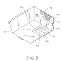
- Fig. 3 is a perspective view of the recording head cartridge 11 seen from blow.
- Reference numeral 11a denotes a recording head having an ink emission part h formed on the side 11b facing the recording sheet 5.
- the ink emission part h includes a linear array of nozzles 11c for emitting black (Bk) ink, nozzles 11d for emitting cyan (C) ink, nozzles 11e for emitting magenta (M) ink, and nozzles 11f for emitting yellow (Y) ink which are arranged along a straight line.
- the cap 24 shown in Fig. 2 is adapted to cover the ink emission part 11h so as to protect the series of nozzles 11c, 11d, 11e, and 11f.
- Reference numeral 11g denotes a plate (on which electrode pads are formed) via which the electrical connection to the flexible circuit film 14 shown in Fig. 2 is achieved.
- the linear array of nozzles 11c for emitting black ink is formed along a longer length than the arrays of nozzles 11d, 11e, and 11f for emitting color inks so that there are a greater number of nozzles 11c for emitting black ink than the nozzles for emitting color inks.
- images recorded by the recording apparatus include only a black component as in the case of a textual document or a line drawing. It is possible to achieve a high-speed recording operation for a black image by forming a greater number of nozzles for emitting black ink as shown in Fig. 3.
- the structure of the recording apparatus 3 is further described below with reference to Figs. 2 and 3.
- the operation of covering the ink emission part h with the cap 24 is performed by moving the recording head cartridge 11 mounted on the carriage 6 to a location (capping position) where the ink emission orifices 11c, 11d, 11e, and 11f are just above the cap 24, and then moving the cap 24 until the cap 24 comes into contact with the ink emission part (ink emission plane) 11h of the recording head cartridge 11.
- the pump 25 is operated while the ink emission part h is covered with the cap 24 so that ink is sucked from the ink emission orifices 11c-11f. In the recovering operation, all inks of colors Bk, Y, M, and C are simultaneously sucked and consumed.
- reference numeral 26 denotes a wiper which moves, depending on the motion of the carriage 6, toward and apart from the location in contact with the ink emission part 11h of the recording head cartridge 11. Dust and dirt can be removed (wiped) from the ink emission part 11h by moving the carriage 6 while the wiper 26 is kept in contact with the ink emission part 11h of the recording head cartridge 11.
- Reference numeral 27 denotes a paper sensor for detecting whether there is a recording sheet.
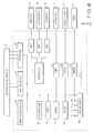
- Fig. 4 is a block diagram illustrating the configuration of the control circuit according to the present embodiment.
- control circuit includes a CPU unit surrounded by a broken line in Fig. 4.
- a CPU (central processing unit) 40 reads a program and various data from a ROM 41 which will be described later or a floppy disk driver (FD) 4 and performs various calculations and processes required in the recording operation.
- a ROM 41 which will be described later
- FD floppy disk driver
- the ROM (read only memory) 41 stores various programs and data such as character codes and dot patterns (character generator, CG) which are used by the CPU 40 to perform the recording operation.
- character codes and dot patterns character generator, CG
- a RAM (random access memory) 42 is a memory capable of reading and writing data from and to it, and includes various memory areas such as a working area used by the CPU 40 to temporarily store data or calculation results, buffer area for storing various data input from a keyboard 1, interface 44, or floppy disk driver 4, and a text area for storing text data.
- the CPU unit is connected to the recording apparatus 3 via the recording head driver 45, the motor driver 46, and the detector 47.
- the recording head driver 45 drives the recording head cartridge 11 mounted on the recording apparatus 3, and the motor driver 46 drives the carriage driving motor 8 and the recording sheet carrying motor (not shown).
- the detector 47 receives information from a carriage sensor (not shown) disposed in the recording apparatus 3 to detect the position of the carriage 6 and also information from the paper sensor 27 for detecting the presence of a recording sheet 5, and transfers the received information to the CPU 40.
- a power supply 48 provides a power supply voltage VH for driving the recording head cartridge 11, a power supply voltage VM for driving the carriage driving motor 8 and the recording sheet feeding motor, a power supply voltage VFDD for driving the floppy disk driver 4, and a power supply voltage VCC for driving the other logic circuits.
- a controller 43 Under the control of the CPU 40, a controller 43 transfers data used by the recording head cartridge to perform the recording operation and also controls the voltage or current the driving power supply VH.
- the CPU unit is connected via a keyboard connector (KBC) 49 to the keyboard 1 serving as an input device for inputting various data required in the recording or editing operation.
- the CPU unit is also connected via a LCD connector (LCDC) 50 to a display 2 constructed with an LCD for displaying the data input via the keyboard 1 and various information.
- LCD LCD
- CRT CRT or other display devices may also be employed as the display 2.
- the CPU unit is also connected via a floppy disk driver connector (FDDC) 51 to the floppy disk driver 4.
- FDDC floppy disk driver connector
- another type of storage medium such as a hard disk or an external RAM may be connected.
- the CPU unit may be connected to interfaces such as RS232C53, Centronics 54, and a modem 55 via an interface connector (IFC) 52 so that the recording apparatus 3 can be controlled by an external controller and the CPU unit can communicate with an external device.
- interfaces such as RS232C53, Centronics 54, and a modem 55 via an interface connector (IFC) 52 so that the recording apparatus 3 can be controlled by an external controller and the CPU unit can communicate with an external device.
- IFC interface connector
- a recording head cartridge 11 After turning on the electric power of a new recording apparatus (step S101), a recording head cartridge 11 is set on a carriage 6. Furthermore, a new black (Bk) ink cartridge 12 and color ink cartridge (in which all three color inks are stored) 13 are set on the recording head cartridge 11 (step S102).
- the count numbers of the remaining-ink counters V(Bk), V(Y), V(M), and V(C) of Bk, Y, M, and C (not shown) provided in the ink-jet recording apparatus are each set to maximum values (step S103). The maximum value is selected to be less than the lowest value of the variation in the amount of ink filled in each ink cartridge so that if the count values of the remaining-ink counters are greater than zero, the actual amounts of ink never become zero.
- a recovering operation is performed to get the recording head 11a recovered into a normal state.
- the amount of ink consumed by suction and preliminary emission in the recovering operation is calculated for each ink on the basis of the evacuating capacity of the pump 25, the amount of each droplet of ink, and the number of droplets emitted.
- the amounts of inks consumed in the recovering operation are set into the variables V(Bk) 1 , V(Y) 1 , V(M) 1 , and V(C) 1 , respectively (step S104).
- the count values of the remaining-ink counters V(Bk), V(Y), V(M), and V(C) are updated by subtracting the consumed amounts from the current count values of the remaining-ink counters (step S105).
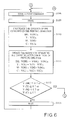
- the count values of the remaining-ink counters V(Bk), V(Y), V(M), and V(C) of the respective inks are checked whether they are equal to or less than zero (step S106). If the count value of any of the remaining-ink counters of ink Bk, Y, M, or C is detected to be equal to or less than zero, then the process goes to step S114 (shown in Fig. 7).
- step S107 if it is determined that the count values of the remaining-ink counters V(Bk), V(Y), V(M), and V(C) of Bk, Y, M, and C are all greater than zero, then the process goes into a waiting state and waits for a recording command (step S107).
- step S108 If a recording command is received (step S108), then recording is performed on one page of recording sheet (step S109) and the amount of ink consumed in the recording operation is calculated for each ink.
- the calculation can be accomplished on the basis of the amount of one droplet of ink and the number of droplets of each ink used in the recording operation.
- the amounts of inks consumed in the recording operation are substituted into the variables V(Bk) 2 , V(Y) 2 , V(M) 2 , and V(C) 2 , respectively (step S110).
- step S111 the count values of the remaining-ink counters V(Bk), V(Y), V(M), and V(C) are updated by subtracting the consumed amounts from the current count values of the respective remaining-ink counters.
- the count values of the remaining-ink counters V(Bk), V(Y), V(M), and V(C) of the respective inks are checked whether they are equal to or less than zero (step S112). If the count value of any of the remaining-ink counters of ink Bk, Y, M, or C is detected to be equal to or less than zero, then the process goes to step S114.
- step S113 If it is determined that the count values of the remaining-ink counters V(Bk), V(Y), V(M), and V(C) of inks Bk, Y, M, and C are all greater than zero, then the process goes into a waiting state and waits for a recording command (step S113).
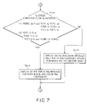
- step S106 or S112 if the count value of any remaining-ink counter V(Y), V(M), or V(C) of ink Y, M, or C is equal to or less than zero, then the process goes to step S114.
- step S114 the count value of the remaining-ink counter having a value greater than zero is compared with the amount of ink consumed in the recovering operation.
- a message is displayed on a display 2 to tell that only the ink cartridge with no remaining ink should be replaced. For example, if the Bk ink becomes zero in the remaining amount, a message such as "Black ink has run out. Please replace it.” is displayed on the display 2 thereby giving information about the ink which should be replaced (step S115). However, if the count value of the remaining-ink counter is smaller than the amount of ink consumed in the recovering operation, a message is displayed on the display 2 to tell that both ink cartridges should be replaced (step S116). Referring now to the flow chart shown in Fig. 8, the operation of replacing ink cartridges is described below.
- step S118 the count value of the remaining-ink counter associated with the replaced ink cartridge is reset to the maximum value (step S118).
- the recovering operation is then performed to get the ink flowing path associated with the replaced ink cartridge recovered into a normal state, and the amount of ink consumed in the recovering operation is calculated (step S119).
- the count values of the remaining-ink counters V(Bk), V(Y), V(M), and V(C) are updated by subtracting the consumed amounts from the current count values of the remaining-ink counters (step S120).
- step S121 since the count values of the remaining-ink counters V(Bk), V(Y), V(M), and V(C) are each greater than zero, the process goes into a waiting state and waits for a recording command (step S121).
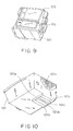
- the procedure of replacing ink cartridges is described for the case where the ink cartridges are mounted on the recording head cartridge shown in Figs. 9 and 10 provided in the recording apparatus 3 described in the first embodiment.
- the recording apparatus is constituted in the same manner as that according to the first embodiment except for the recording head cartridge, and thus it is not described in further detail herein.
- Fig. 9 is a perspective view of the recording head cartridge 101 seen from above.
- a high-density black ink cartridge 102 storing relatively high-density black ink and a low-density black ink cartridge 103 storing relatively low-density black ink are mounted in a removable fashion and such that the respective inks are supplied to the recording head cartridges 101.
- This recording head cartridge 101 is capable of recording both high-density dots and low-density dots.
- Fig. 10 is a perspective view illustrating the detailed structure of the recording head cartridge 101 seen from below.
- reference numeral 101a denotes a recording head having an ink emission part 101f formed on the side 101b facing the recording sheet 5.
- Two linear arrays of nozzles 101c and 101d are formed on the ink emission part 101f in such a manner that the two linear arrays are located close to each other and extend in parallel.
- the cap 24 shown in Fig. 2 is adapted to come into contact with the ink emission part 101f so as to protect the nozzle arrays 101c and 101d.
- the nozzle array 101c is used to emit the black ink (high-density black ink) supplied from the high-density black ink cartridge 102
- the nozzle array 101d is used to emit the black ink (low-density black ink) supplied from the low-density black ink cartridge 103.
- reference numeral 101e denotes a plate (on which electrode pads are formed) via which the electrical connection to the flexible circuit film 14 shown in Fig. 2 is achieved.
- the break-even point is determined for the case where a plurality of ink cartridges are replaced at the same time and for the case where ink cartridges are replaced at different times, on the assumption that the standard document is recorded on the recording medium. On the basis of the determined break-even point, it is determined whether a plurality of ink cartridges should be replaced at the same time or at different times.
- the recording of the standard document refers to the operation of recording a textual or graphical image in which all inks are consumed at the same ratio relative to the maximum ink capacity of the respective ink cartridges.
- the inks are all equal in cost as long as the ratios of the amounts of consumed inks relative to the maximum ink capacity are equal.
- the amount of ink consumed in the recovering operation is denoted for each ink cartridge as follows:
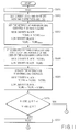
- a recording head cartridge 101 After turning on the electric power of a new recording apparatus (step S301), a recording head cartridge 101 is set on a carriage 6. Furthermore, a new high-density black ink cartridge 102 and low-density black ink cartridge 103 are set on the recording head cartridge 101 (step S302).
- the count numbers of the remaining-ink counters V(Tk) and V(tB) of the high- and low-density black inks are each set to the maximum values (step S303).
- the maximum values are selected to be less than the lowest value of the variation in the amount of ink fully filled in each ink cartridge so that if the count values of the remaining-ink counters V(TB) and V(tB) are greater than zero, the actual amounts of ink never become zero.
- a recovering operation is performed to get the recording head 101a recovered into a normal state.
- the amount of ink consumed by suction and preliminary emission in the recovering operation is calculated for each ink on the basis of the evacuating capacity of the pump 25, the amount of each droplet of ink, and the number of droplets emitted.
- the amounts of ink consumed in the recovering operation are set into the variables V(TB) 1 and V(tB) 1 , respectively (step S304).
- the count values of the remaining-ink counters V(TB) and V(tB) are updated by subtracting the consumed amounts from the current count values of the remaining-ink counters (step S305).
- the count values of the remaining-ink counters V(TB) and V(tB) of the respective inks are checked whether they are equal to or less than zero (step S306). If the count value of any of the remaining-ink counters of the high- or low-density black ink is detected to be equal to or less than zero, then the process goes to step S314 (Fig. 13).
- step S307 If it is determined that the count values of the remaining-ink counters V(TB) and V(tB) of the high- and low-density black inks are both greater than zero, then the process goes into a waiting state and waits for a recording command (step S307).
- step S308 If a recording command is received (step S308), then recording is performed on one page of recording sheet (step S309) and the amount of ink consumed in the recording operation is calculated for each ink.
- the calculation can be accomplished on the basis of the amount of one droplet of ink and the number of droplets of each ink used in the recording operation.
- the amounts of inks consumed in the recording operation are substituted into the variables V(TB) 2 and V(tB) 2 , respectively (step S310).
- step S311 the count values of the remaining-ink counters V(TB) and V(tB) are updated by subtracting the consumed amounts from the current count values of the respective remaining-ink counters.
- the count values of the remaining-ink counters V(TB) and V(tB) of the respective inks are checked whether they are equal to or less than zero (step S312). If the count value of any of the remaining-ink counters V(TB) or V(tB) associated with the high- or low-density black ink is equal to or less than zero, then the process goes to step S314.
- step S313 If it is determined that the count values of the remaining-ink counters V(TB) and V(tB) associated with the high- and low-density black inks are both greater than zero, then the process goes into a waiting state and waits for a recording command (step S313).
- step S306 or S312 if the count value of any remaining-ink counter V(TB) or V(tB) associated with the high- or low-density black ink is equal to or less than zero, then the process goes to step S114.
- step S314 Fig. 13
- a message is displayed on a display 2 to tell that only the ink cartridge with no remaining ink should be replaced. For example, if the high-density black ink becomes zero in the remaining amount, a message such as "High-density black ink has run out. Please replace it.” is displayed on the display 2 (step S315).
- step S316 if the count value of the remaining-ink counter is smaller than the amount of ink corresponding to the break-even point, a message is displayed on the display 2 to tell that both ink cartridges should be replaced (step S316).
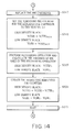
- the operation of replacing the ink cartridge is described below with reference to Fig. 14.
- the count value of the remaining-ink counter associated with the replaced ink cartridge is reset to the maximum value (step S318).
- the recovering operation is then performed to get the ink flowing path associated with the replaced ink cartridge recovered into a normal state, and the amount of ink consumed in the recovering operation is calculated (step S319).
- the count values of the remaining-ink counters V(TB) and V(tB) are updated by subtracting the amounts of ink consumed in the recovering operation from the current count values of the remaining-ink counters (step S320).
- step S321 since the count values of the remaining-ink counters V(TB) and V(tB) are both greater than zero, the process goes into a waiting state and waits for a recording command (step S321).
- the break-even point in terms of cost is calculated for the case where only the ink cartridge having no remaining ink is replaced and for the case where another ink cartridge is also replaced at the same time, thereby determining the optimum manner in which ink cartridges are replaced. That is, it is determined whether only the ink cartridge whose remaining amount of ink has become low is replaced or another ink cartridge in addition to that is also replaced, on the basis of the cost needed for the replacement. This makes it possible to replace the ink cartridges with the minimized cost. If the technique according to the present embodiment is employed, it is possible to properly replace ink cartridges even in the case where the cost varies depending on the type of ink contained in the respective ink cartridges.
- the present invention is not limited to the above-described conditions in terms of the type of the document to be recorded, the cost of inks, etc.
- the present invention may also be applied to other conditions where the recording apparatus is used.
- the invention is not limited to the recording apparatus having the recording cartridge of the type described in the first or second embodiment.
- the invention may be applied to a recording apparatus having ink cartridges and recording heads for emitting ink supplied from ink cartridges wherein the recovering operation is performed at the same time on the plurality of recording heads adapted to emit inks supplied from the plurality of ink cartridges instead of separately performing the recovering operation on the respective recording heads.
- black ink is stored in a single ink cartridge and other color inks (Y, M, C) are stored in another single cartridge.
- the present invention may also be applied to a combination if ink cartridges in which each color ink is stored in its own separate cartridge.
- the technique disclosed in the first embodiment may also be applied to the recording apparatus according to the second embodiment which uses high- and low-density inks or which uses any different types of inks.
- the technique disclosed ion the second embodiment may be applied to the recording apparatus using a black ink and a plurality of color inks.
- the invention is not limited to inks containing pigments used in the recording operation but may also be applied to auxiliary agents which react with the ink on the recording sheet and improves the fastness of the recorded image.
- the ink cartridges are removable from the recording head.
- the present invention may also be applied to the structure in which the recording head and the ink cartridges are formed in a single piece.
- the invention may also be applied to the structure in which the recording head and the ink cartridges are formed in a single piece and there is provided ink supply members through which ink can be supplied to the cartridges using for example a dropping pipette.
- the invention is applied to the serial type recording apparatus.
- the invention may also be applied to a full line type recording apparatus provided with a full line head capable of recording over the entire length of the width of a recording sheet.
- the invention is not limited to the word processor, but may also be applied to various types of recording apparatus.
- the invention may be applied to an ink-jet recording apparatus used in a printer connected to a computer so as to output an image, a facsimile machine for transmitting and receiving information via a telephone line, and a copying machine for scanning an image and outputting it.
- the means for detecting the amount of remaining ink calculates the amount of remaining ink on the basis of the amount of ink consumed in various operations starting at the time when an ink cartridge is replaced.
- the present invention may also be applied to means which detects the amount of remaining ink based on various techniques.
- a display is employed as informing means.
- the invention may also be applied to informing means based on other techniques such as a device adapted to present information to a user by changing the number of frequency of a sound or light using a buzzer or a lamp.
- An LED may be employed as a means for emitting light.
- This system is advantageous to the On-Demand type in particular because an electro-thermal converting element disposed to align to a sheet or a liquid passage in which a liquid (ink) is held is applied with at least one drive signal which corresponds to information to be recorded and which enables the temperature of the electro-thermal converting element to be rapidly raised higher than a nucleate boiling point, so that thermal energy is generated in the electro-thermal converting element and film boiling is caused to take place on the surface of the recording head which is heated.
- bubbles can be respectively formed in the liquid (ink) in response to the drive signals. Owing to the enlargement and contraction of the bubbles, the liquid (ink) is discharged through the discharging orifice, so that at least one droplet is formed.
- the aforesaid drive signal is made to be a pulse signal, a further satisfactory effect can be obtained in that the bubbles can immediately and properly be enlarged/contracted and the liquid (ink) can be discharged while exhibiting excellent responsibility.
- the present invention can effectively be embodied in a structure in which a common slit is made to be the discharge portion of a plurality of electro-thermal converting elements and which is disclosed in Japanese Patent Laid-Open No. 59-123670 and a structure in which an opening for absorbing thermal energy pressure waves is defined to align to the discharge part and which is disclosed in Japanese Patent Laid-Open No. 59-138461. Namely, according to the present invention, recording operation can be performed surely and effectively irrespective of the form of the recording head.
- the present invention may be applied to a full line type recording head having a length which corresponds to the maximum width of the recording medium, which can be recorded by the recording apparatus.
- Such a recording head may be either a structure capable of realizing the aforesaid length and formed by combining a plurality of recording heads or a structure formed by an integrally formed recording head.
- the present invention can also be effectively applied to a recording head fixed to the body of the apparatus, a structure having an interchangeable chip type recording head which can be electrically connected to the body of the apparatus or to which an ink can be supplied from the body of the apparatus when it is mounted on the body of the apparatus, or a cartridge type recording head provided with an ink tank integrally formed to the recording head itself among the above-exemplified serial type recording heads.
- a recording head recovery means and an auxiliary means of the recording apparatus it is preferable to additionally provide a recording head recovery means and an auxiliary means of the recording apparatus according to the present invention because the effects of the present invention can further be stabilized.
- an effect can be obtained in that the recording operation can be stably performed by providing a recording head capping means, a cleaning means, a pressurizing or sucking means, an electro-thermal converting element or another heating device or an auxiliary heating means formed by combining the aforesaid elements and by performing a preliminary discharge mode in which a discharge is performed individually from the recording operation.
- inks which are solid at a temperature lower than room temperature, but are softened or liquefied at room temperature may be used.
- the temperature of an ink is usually controlled in a range from 30°C to 70°C so as to adjust the viscosity of the ink within a stable discharge range. Therefore, it is only necessary to use inks which are liquefied in response to a record signal applied.
- inks the temperature rise of which is prevented by positively using the temperature rise due to the thermal energy as energy of state change from the solid state to the liquid state of ink or inks which are solidified when it is allowed to stand in order to prevent the evaporation of ink may be used. That is, inks which are liquefied by thermal energy for the first time such as inks liquefied by thermal energy applied in response to the record signal and discharged as ink droplets or inks which already begin to solidify when they reach the recording medium may be employed in the present invention.
- an ink may be, in the form of liquid or solid, held by a recess of a porous sheet or a through hole as disclosed in Japanese Patent Laid-Open No. 54-56847 or 60-71260 and disposed to confront the electro-thermal converting element. It is most preferable for the above-described inks that an ink be discharged by the aforesaid film boiling method.
- the ink-jet recording apparatus may be in the form, in addition to that used as an image-output terminal for information processing equipment such as a computer, of a copying machine combined with a reader and moreover, of a facsimile terminal equipment having a transmit-receive function or the like.
- the present invention may be applied either to a system including a plurality of devices (such as a host computer, interface device, reader, printer, etc.) or to an apparatus constructed in a single form (such as a copying machine, facsimile machine, etc.).
- a system including a plurality of devices (such as a host computer, interface device, reader, printer, etc.) or to an apparatus constructed in a single form (such as a copying machine, facsimile machine, etc.).
- the objects of the present invention may also be achieved by supplying a storage medium, on which a software program implementing the functions of any of the embodiments described above is stored, to a system or an apparatus whereby a computer (CPU or MPU) in the system or apparatus reads and executes the program code stored on the storage medium.
- a computer CPU or MPU
- Storage media which can be preferably employed in the present invention to supply the program code include a floppy disk, hard disk, optical disk, magneto-optical disk, CD-ROM, CD-R, magnetic tape, non-volatile memory card, and ROM.
- the scope of the present invention includes not only such a system in which the functions of any embodiment described above is implemented simply by reading and executing a program code on a computer but also a system in which a part of or the whole of process instructed by the program code is performed using an OS (operating system) on the computer.
- OS operating system
- the present invention provides a recording apparatus and a method of controlling the operation of the recording apparatus in which the timing of replacing or refilling the ink storage means which supplies ink to a recording head so that the operation of recovering the recoding head is performed in a highly efficient manner thus minimizing the amount of ink and the time consumed in an useless manner.
Landscapes
- Ink Jet (AREA)
Applications Claiming Priority (3)
| Application Number | Priority Date | Filing Date | Title |
|---|---|---|---|
| JP16303097A JP3288954B2 (ja) | 1997-06-19 | 1997-06-19 | 記録装置及び該記録装置の制御方法 |
| JP16303097 | 1997-06-19 | ||
| JP163030/97 | 1997-06-19 |
Publications (3)
| Publication Number | Publication Date |
|---|---|
| EP0885731A2 true EP0885731A2 (de) | 1998-12-23 |
| EP0885731A3 EP0885731A3 (de) | 2000-02-02 |
| EP0885731B1 EP0885731B1 (de) | 2007-04-11 |
Family
ID=15765861
Family Applications (1)
| Application Number | Title | Priority Date | Filing Date |
|---|---|---|---|
| EP98304871A Expired - Lifetime EP0885731B1 (de) | 1997-06-19 | 1998-06-19 | Aufzeichnungsgerät und sein Steuerverfahren |
Country Status (4)
| Country | Link |
|---|---|
| US (1) | US6070958A (de) |
| EP (1) | EP0885731B1 (de) |
| JP (1) | JP3288954B2 (de) |
| DE (1) | DE69837509T2 (de) |
Cited By (9)
| Publication number | Priority date | Publication date | Assignee | Title |
|---|---|---|---|---|
| DE19958948A1 (de) * | 1999-11-26 | 2001-06-07 | Francotyp Postalia Gmbh | Verfahren zur Bestimmung der Anzahl von mit einer Tintenrestmenge ausführbaren Drucken und Anordnung zur Durchführung des Verfahrens |
| EP1055520A4 (de) * | 1998-02-13 | 2001-08-22 | Seiko Epson Corp | Tintenstrahldrucker, dafür geeignete tanktureinheit und verfahren zur wiederherstellung des tintentröpfchenausstossvermögens |
| WO2002004215A1 (fr) * | 2000-07-07 | 2002-01-17 | Seiko Epson Corporation | Recipient de liquide, appareil d'impression a jet d'encre, dispositif et procede de commande de cet appareil, dispositif et procede detection de consommation de liquide |
| EP1270226A3 (de) * | 2001-06-14 | 2003-02-26 | Seiko Epson Corporation | Verfahren und Vorrichtung zur Berechnung der Tintenverbrauchsmenge, Tintenstrahldrucker mit der Vorrichtung, Druckkostenberechnungssystem, und Farbstoffzufuhrmanagementsystem |
| US7086281B2 (en) | 2000-07-28 | 2006-08-08 | Seiko Epson Corporation | Detector of liquid consumption condition |
| US7137679B2 (en) | 2000-05-18 | 2006-11-21 | Seiko Epson Corporation | Ink consumption detecting method, and ink jet recording apparatus |
| US7156506B2 (en) | 2000-06-15 | 2007-01-02 | Seiko Epson Corporation | Liquid charging method, liquid container, and method for manufacturing the same |
| US7175244B2 (en) | 1999-05-20 | 2007-02-13 | Seiko Epson Corporation | Liquid container having liquid consumption detecting device |
| US7225670B2 (en) | 2000-05-18 | 2007-06-05 | Seiko Epson Corporation | Mounting structure, module, and liquid container |
Families Citing this family (22)
| Publication number | Priority date | Publication date | Assignee | Title |
|---|---|---|---|---|
| AUPP702498A0 (en) * | 1998-11-09 | 1998-12-03 | Silverbrook Research Pty Ltd | Image creation method and apparatus (ART77) |
| JP4314702B2 (ja) * | 1998-11-26 | 2009-08-19 | セイコーエプソン株式会社 | 印刷装置、書込方法およびプリンタ |
| US6658219B1 (en) * | 1999-09-30 | 2003-12-02 | Fuji Photo Film Co., Ltd. | Method, device, system and recording medium for detecting improper cartridge, and cartridge |
| PT1283110E (pt) | 2000-05-18 | 2009-04-20 | Seiko Epson Corp | Processo de detecção de consumo de tinta e aparelho de registo de jacto de tinta |
| US6392546B1 (en) | 2000-09-07 | 2002-05-21 | Judson L. Smith | Hand washing compliance measurement and recording system |
| US7343298B2 (en) * | 2000-10-20 | 2008-03-11 | Seiko Epson Corporation | Method and system for supply of expendables |
| JP3543781B2 (ja) | 2001-04-13 | 2004-07-21 | セイコーエプソン株式会社 | インクジェット式記録装置 |
| US7597122B1 (en) | 2001-07-26 | 2009-10-06 | Smith Judson L | Apparatus and method to monitor the usage of a network system of personal hand sanitizing dispensers |
| US6883563B2 (en) | 2001-07-26 | 2005-04-26 | Judson L. Smith | Apparatus and method to monitor the usage of a network system of personal hand sanitizing dispensers |
| JP2003096343A (ja) * | 2001-09-19 | 2003-04-03 | Brother Ind Ltd | インクジェット記録用水性インク |
| US6837560B2 (en) * | 2002-06-05 | 2005-01-04 | Canon Kabushiki Kaisha | Ink-jet recording apparatus, and method for operating the same |
| JP2004122424A (ja) * | 2002-09-30 | 2004-04-22 | Matsushita Electric Ind Co Ltd | インクジェット式記録装置 |
| US7044574B2 (en) | 2002-12-30 | 2006-05-16 | Lexmark International, Inc. | Method and apparatus for generating and assigning a cartridge identification number to an imaging cartridge |
| JP2006056013A (ja) * | 2004-08-17 | 2006-03-02 | Seiko Epson Corp | インクジェットプリンタ、およびそのインクカートリッジ交換時期監視方法 |
| JP4622777B2 (ja) * | 2004-09-27 | 2011-02-02 | セイコーエプソン株式会社 | 表示制御装置 |
| USD512648S1 (en) | 2004-12-15 | 2005-12-13 | Smith Judson L | Dispenser for fluid material |
| JP5223388B2 (ja) * | 2008-03-12 | 2013-06-26 | 株式会社リコー | 画像形成装置、画像形成方法及びプログラム |
| JP5332431B2 (ja) | 2008-09-12 | 2013-11-06 | セイコーエプソン株式会社 | 液体供給装置、印刷装置及び液体供給装置の制御方法 |
| JP5488239B2 (ja) * | 2010-06-17 | 2014-05-14 | ブラザー工業株式会社 | 画像記録装置 |
| JP6797554B2 (ja) * | 2016-05-06 | 2020-12-09 | キヤノン株式会社 | 通知装置および記録装置 |
| KR102404582B1 (ko) * | 2018-11-06 | 2022-06-02 | 휴렛-팩커드 디벨롭먼트 컴퍼니, 엘.피. | 토너 리필 과정에서의 에러 처리 방법 |
| JP7290059B2 (ja) * | 2019-04-26 | 2023-06-13 | ブラザー工業株式会社 | 画像記録装置 |
Citations (7)
| Publication number | Priority date | Publication date | Assignee | Title |
|---|---|---|---|---|
| US4313124A (en) | 1979-05-18 | 1982-01-26 | Canon Kabushiki Kaisha | Liquid jet recording process and liquid jet recording head |
| US4345262A (en) | 1979-02-19 | 1982-08-17 | Canon Kabushiki Kaisha | Ink jet recording method |
| US4463359A (en) | 1979-04-02 | 1984-07-31 | Canon Kabushiki Kaisha | Droplet generating method and apparatus thereof |
| US4723129A (en) | 1977-10-03 | 1988-02-02 | Canon Kabushiki Kaisha | Bubble jet recording method and apparatus in which a heating element generates bubbles in a liquid flow path to project droplets |
| JPH0516384A (ja) | 1991-07-08 | 1993-01-26 | Canon Inc | インクジエツト記録装置 |
| US5414452A (en) | 1992-06-08 | 1995-05-09 | Ing. C. Olivetti & C., S.P.A. | Recognition of ink expiry in an ink jet printing head |
| JPH09156126A (ja) | 1995-12-05 | 1997-06-17 | Brother Ind Ltd | インクジェットプリンタ |
Family Cites Families (17)
| Publication number | Priority date | Publication date | Assignee | Title |
|---|---|---|---|---|
| JPS5936879B2 (ja) * | 1977-10-14 | 1984-09-06 | キヤノン株式会社 | 熱転写記録用媒体 |
| US4330787A (en) * | 1978-10-31 | 1982-05-18 | Canon Kabushiki Kaisha | Liquid jet recording device |
| US4558333A (en) * | 1981-07-09 | 1985-12-10 | Canon Kabushiki Kaisha | Liquid jet recording head |
| US4432005A (en) * | 1982-05-10 | 1984-02-14 | Advanced Color Technology, Inc. | Ink control system for ink jet printer |
| JPS58194561A (ja) * | 1982-05-11 | 1983-11-12 | Canon Inc | 記録装置 |
| JPS59123670A (ja) * | 1982-12-28 | 1984-07-17 | Canon Inc | インクジエツトヘツド |
| JPS59138461A (ja) * | 1983-01-28 | 1984-08-08 | Canon Inc | 液体噴射記録装置 |
| JPS6071260A (ja) * | 1983-09-28 | 1985-04-23 | Erumu:Kk | 記録装置 |
| DE3856561T2 (de) * | 1987-04-15 | 2004-06-09 | Canon K.K. | Ein Flüssigkeitsrestmengendetektor und ein Flüssigkeitseinspritzregistriergerät mit diesem Detektor |
| JP3180401B2 (ja) * | 1991-12-24 | 2001-06-25 | セイコーエプソン株式会社 | インクジェットプリンタにおけるインク吐出回復装置 |
| US5682183A (en) * | 1993-11-22 | 1997-10-28 | Hewlett-Packard Company | Ink level sensor for an inkjet print cartridge |
| JP3258164B2 (ja) * | 1994-03-09 | 2002-02-18 | キヤノン株式会社 | プリント装置およびプリント方法 |
| JP3216856B2 (ja) * | 1994-05-19 | 2001-10-09 | キヤノン株式会社 | 記録装置及びインク残量表示方法 |
| JPH07323645A (ja) * | 1994-05-31 | 1995-12-12 | Canon Inc | 記録装置 |
| JP3219641B2 (ja) * | 1994-07-15 | 2001-10-15 | キヤノン株式会社 | インクジェット記録装置およびインクの残量低下の判別方法ならびに情報処理装置 |
| US6771378B2 (en) * | 1994-10-20 | 2004-08-03 | Canon Kabushiki Kaisha | Information processing apparatus which obtains information concerning residual ink amount from an attached ink jet printer |
| JP3450643B2 (ja) * | 1996-04-25 | 2003-09-29 | キヤノン株式会社 | 液体収容容器への液体補充方法、該補充方法を用いる液体吐出記録装置、液体補充容器、液体収容容器およびヘッドカートリッジ |
-
1997
- 1997-06-19 JP JP16303097A patent/JP3288954B2/ja not_active Expired - Fee Related
-
1998
- 1998-06-17 US US09/098,423 patent/US6070958A/en not_active Expired - Lifetime
- 1998-06-19 DE DE69837509T patent/DE69837509T2/de not_active Expired - Lifetime
- 1998-06-19 EP EP98304871A patent/EP0885731B1/de not_active Expired - Lifetime
Patent Citations (8)
| Publication number | Priority date | Publication date | Assignee | Title |
|---|---|---|---|---|
| US4723129A (en) | 1977-10-03 | 1988-02-02 | Canon Kabushiki Kaisha | Bubble jet recording method and apparatus in which a heating element generates bubbles in a liquid flow path to project droplets |
| US4740796A (en) | 1977-10-03 | 1988-04-26 | Canon Kabushiki Kaisha | Bubble jet recording method and apparatus in which a heating element generates bubbles in multiple liquid flow paths to project droplets |
| US4345262A (en) | 1979-02-19 | 1982-08-17 | Canon Kabushiki Kaisha | Ink jet recording method |
| US4463359A (en) | 1979-04-02 | 1984-07-31 | Canon Kabushiki Kaisha | Droplet generating method and apparatus thereof |
| US4313124A (en) | 1979-05-18 | 1982-01-26 | Canon Kabushiki Kaisha | Liquid jet recording process and liquid jet recording head |
| JPH0516384A (ja) | 1991-07-08 | 1993-01-26 | Canon Inc | インクジエツト記録装置 |
| US5414452A (en) | 1992-06-08 | 1995-05-09 | Ing. C. Olivetti & C., S.P.A. | Recognition of ink expiry in an ink jet printing head |
| JPH09156126A (ja) | 1995-12-05 | 1997-06-17 | Brother Ind Ltd | インクジェットプリンタ |
Cited By (21)
| Publication number | Priority date | Publication date | Assignee | Title |
|---|---|---|---|---|
| EP1055520A4 (de) * | 1998-02-13 | 2001-08-22 | Seiko Epson Corp | Tintenstrahldrucker, dafür geeignete tanktureinheit und verfahren zur wiederherstellung des tintentröpfchenausstossvermögens |
| EP1281526A1 (de) * | 1998-02-13 | 2003-02-05 | Seiko Epson Corporation | Verfahren zur Wiederherstellung der Tintenstrahltropfenausstossfähigkeit |
| US7281776B2 (en) | 1999-05-20 | 2007-10-16 | Seiko Epson Corporation | Liquid container having liquid consumption detecing device |
| US7188520B2 (en) | 1999-05-20 | 2007-03-13 | Seiko Epson Corporation | Liquid consumption status detecting method, liquid container, and ink cartridge |
| US7175244B2 (en) | 1999-05-20 | 2007-02-13 | Seiko Epson Corporation | Liquid container having liquid consumption detecting device |
| US7434462B2 (en) | 1999-05-20 | 2008-10-14 | Seiko Epson Corporation | Liquid consumption status detecting method, liquid container, and ink cartridge |
| US7267000B1 (en) | 1999-05-20 | 2007-09-11 | Seiko Epson Corporation | Liquid consumption status detecting method, liquid container, and ink cartridge |
| US7325450B2 (en) | 1999-05-20 | 2008-02-05 | Seiko Epson Corporation | Liquid consumption status detecting method, liquid container, and ink cartridge |
| DE19958948B4 (de) * | 1999-11-26 | 2005-06-02 | Francotyp-Postalia Ag & Co. Kg | Verfahren zur Bestimmung der Anzahl von mit einer Tintenrestmenge ausführbaren Drucken und Vorrichtung zur Durchführung des Verfahrens |
| DE19958948A1 (de) * | 1999-11-26 | 2001-06-07 | Francotyp Postalia Gmbh | Verfahren zur Bestimmung der Anzahl von mit einer Tintenrestmenge ausführbaren Drucken und Anordnung zur Durchführung des Verfahrens |
| US6428132B1 (en) | 1999-11-26 | 2002-08-06 | Francotyp-Postalia Ag & Co. | Method for determining the number of normal imprints implementable with a remaining ink quantity and arrangement for the implementation of the method |
| US7137679B2 (en) | 2000-05-18 | 2006-11-21 | Seiko Epson Corporation | Ink consumption detecting method, and ink jet recording apparatus |
| US7878609B2 (en) | 2000-05-18 | 2011-02-01 | Seiko Epson Corporation | Mounting structure, module, and liquid container |
| US7225670B2 (en) | 2000-05-18 | 2007-06-05 | Seiko Epson Corporation | Mounting structure, module, and liquid container |
| US7156506B2 (en) | 2000-06-15 | 2007-01-02 | Seiko Epson Corporation | Liquid charging method, liquid container, and method for manufacturing the same |
| US7798620B2 (en) | 2000-06-15 | 2010-09-21 | Seiko Epson Corporation | Method of manufacturing a liquid container |
| US7306308B2 (en) | 2000-07-07 | 2007-12-11 | Seiko Epson Corporation | Liquid container, ink jet recording apparatus, apparatus and method for controlling the same, apparatus and method for detecting liquid consumption state |
| US7008034B2 (en) * | 2000-07-07 | 2006-03-07 | Seiko Epson Corporation | Liquid container, ink-jet recording apparatus, device and method for controlling the apparatus, liquid consumption sensing device and method |
| WO2002004215A1 (fr) * | 2000-07-07 | 2002-01-17 | Seiko Epson Corporation | Recipient de liquide, appareil d'impression a jet d'encre, dispositif et procede de commande de cet appareil, dispositif et procede detection de consommation de liquide |
| US7086281B2 (en) | 2000-07-28 | 2006-08-08 | Seiko Epson Corporation | Detector of liquid consumption condition |
| EP1270226A3 (de) * | 2001-06-14 | 2003-02-26 | Seiko Epson Corporation | Verfahren und Vorrichtung zur Berechnung der Tintenverbrauchsmenge, Tintenstrahldrucker mit der Vorrichtung, Druckkostenberechnungssystem, und Farbstoffzufuhrmanagementsystem |
Also Published As
| Publication number | Publication date |
|---|---|
| US6070958A (en) | 2000-06-06 |
| EP0885731A3 (de) | 2000-02-02 |
| DE69837509D1 (de) | 2007-05-24 |
| JPH1110900A (ja) | 1999-01-19 |
| DE69837509T2 (de) | 2007-09-06 |
| JP3288954B2 (ja) | 2002-06-04 |
| EP0885731B1 (de) | 2007-04-11 |
Similar Documents
| Publication | Publication Date | Title |
|---|---|---|
| US6070958A (en) | Recording apparatus and method of controlling the same | |
| US5949447A (en) | Ink jet printer having exchangeable recording devices, a recovery control method and an ink jet printer that manages an amount of ink remaining | |
| US5530462A (en) | Recovery technique for ink jet recording apparatus | |
| US5831646A (en) | Controlling a discharge recovery operation according to a condition relating to an ink cartridge | |
| JP5385548B2 (ja) | 記録装置 | |
| EP0916496B1 (de) | Druckapparat und Verfahren zur Drucksteuerung | |
| EP0626267A2 (de) | Tintenstrahlaufzeichnungsvorrichtung | |
| US7997678B2 (en) | Inkjet recording apparatus and method for recording an image | |
| EP0630750B1 (de) | Aufzeichnungsgerät mit einer Abweichungseinstellvorrichtung | |
| US6729711B1 (en) | Ink jet recording apparatus | |
| JPH0998243A (ja) | 記録装置及びその記録装置を用いたファクシミリ装置 | |
| EP0688673B1 (de) | Aufzeichnungsgerät | |
| EP1393915B1 (de) | Tintenstrahlgerät und Vorausstosssteuerungsverfahren dafür | |
| US5673070A (en) | Recording apparatus for controlling recording in accordance with battery capacity | |
| JP3577012B2 (ja) | インクの残量検出方法およびインクジェット記録装置 | |
| EP2156955A2 (de) | Tintenstrahldruckvorrichtung | |
| US6238034B1 (en) | Ink-jet recording methods and apparatuses | |
| JPH09295409A (ja) | 記録装置及びインク検知手段の動作不良検出方法 | |
| EP0694394B1 (de) | Aufzeichnungsgerät und Verfahren zum Schutz vor Temperatur-Überschreitung | |
| US20050062791A1 (en) | Image forming device and control method therefor | |
| JP2000296627A (ja) | 印刷装置、印刷装置クリーニング方法および情報記録媒体 | |
| JP2000246922A (ja) | 記録装置、該記録装置を用いたファクシミリ装置および記録装置の吐出回復方法 | |
| US20130249980A1 (en) | Printing apparatus, printing system, and control method for the same system | |
| JP2002337366A (ja) | 画像記録装置、情報処理装置、画像記録システムおよびそれらの制御方法 | |
| JPH11129495A (ja) | インクジェットプリンタのインク残量感知機構及び方法 |
Legal Events
| Date | Code | Title | Description |
|---|---|---|---|
| PUAI | Public reference made under article 153(3) epc to a published international application that has entered the european phase |
Free format text: ORIGINAL CODE: 0009012 |
|
| AK | Designated contracting states |
Kind code of ref document: A2 Designated state(s): DE ES FR GB IT NL |
|
| AX | Request for extension of the european patent |
Free format text: AL;LT;LV;MK;RO;SI |
|
| PUAL | Search report despatched |
Free format text: ORIGINAL CODE: 0009013 |
|
| AK | Designated contracting states |
Kind code of ref document: A3 Designated state(s): AT BE CH CY DE DK ES FI FR GB GR IE IT LI LU MC NL PT SE |
|
| AX | Request for extension of the european patent |
Free format text: AL;LT;LV;MK;RO;SI |
|
| 17P | Request for examination filed |
Effective date: 20000619 |
|
| AKX | Designation fees paid |
Free format text: DE ES FR GB IT NL |
|
| 17Q | First examination report despatched |
Effective date: 20031024 |
|
| GRAP | Despatch of communication of intention to grant a patent |
Free format text: ORIGINAL CODE: EPIDOSNIGR1 |
|
| GRAS | Grant fee paid |
Free format text: ORIGINAL CODE: EPIDOSNIGR3 |
|
| GRAA | (expected) grant |
Free format text: ORIGINAL CODE: 0009210 |
|
| AK | Designated contracting states |
Kind code of ref document: B1 Designated state(s): DE ES FR GB IT NL |
|
| REG | Reference to a national code |
Ref country code: GB Ref legal event code: FG4D |
|
| REF | Corresponds to: |
Ref document number: 69837509 Country of ref document: DE Date of ref document: 20070524 Kind code of ref document: P |
|
| PG25 | Lapsed in a contracting state [announced via postgrant information from national office to epo] |
Ref country code: ES Free format text: LAPSE BECAUSE OF FAILURE TO SUBMIT A TRANSLATION OF THE DESCRIPTION OR TO PAY THE FEE WITHIN THE PRESCRIBED TIME-LIMIT Effective date: 20070722 |
|
| ET | Fr: translation filed | ||
| NLV1 | Nl: lapsed or annulled due to failure to fulfill the requirements of art. 29p and 29m of the patents act | ||
| PG25 | Lapsed in a contracting state [announced via postgrant information from national office to epo] |
Ref country code: NL Free format text: LAPSE BECAUSE OF FAILURE TO SUBMIT A TRANSLATION OF THE DESCRIPTION OR TO PAY THE FEE WITHIN THE PRESCRIBED TIME-LIMIT Effective date: 20070411 |
|
| PLBE | No opposition filed within time limit |
Free format text: ORIGINAL CODE: 0009261 |
|
| STAA | Information on the status of an ep patent application or granted ep patent |
Free format text: STATUS: NO OPPOSITION FILED WITHIN TIME LIMIT |
|
| 26N | No opposition filed |
Effective date: 20080114 |
|
| REG | Reference to a national code |
Ref country code: FR Ref legal event code: PLFP Year of fee payment: 18 |
|
| PGFP | Annual fee paid to national office [announced via postgrant information from national office to epo] |
Ref country code: DE Payment date: 20150630 Year of fee payment: 18 Ref country code: GB Payment date: 20150626 Year of fee payment: 18 |
|
| PGFP | Annual fee paid to national office [announced via postgrant information from national office to epo] |
Ref country code: IT Payment date: 20150611 Year of fee payment: 18 |
|
| PGFP | Annual fee paid to national office [announced via postgrant information from national office to epo] |
Ref country code: FR Payment date: 20150626 Year of fee payment: 18 |
|
| REG | Reference to a national code |
Ref country code: DE Ref legal event code: R119 Ref document number: 69837509 Country of ref document: DE |
|
| GBPC | Gb: european patent ceased through non-payment of renewal fee |
Effective date: 20160619 |
|
| REG | Reference to a national code |
Ref country code: FR Ref legal event code: ST Effective date: 20170228 |
|
| PG25 | Lapsed in a contracting state [announced via postgrant information from national office to epo] |
Ref country code: FR Free format text: LAPSE BECAUSE OF NON-PAYMENT OF DUE FEES Effective date: 20160630 Ref country code: DE Free format text: LAPSE BECAUSE OF NON-PAYMENT OF DUE FEES Effective date: 20170103 |
|
| PG25 | Lapsed in a contracting state [announced via postgrant information from national office to epo] |
Ref country code: GB Free format text: LAPSE BECAUSE OF NON-PAYMENT OF DUE FEES Effective date: 20160619 |
|
| PG25 | Lapsed in a contracting state [announced via postgrant information from national office to epo] |
Ref country code: IT Free format text: LAPSE BECAUSE OF NON-PAYMENT OF DUE FEES Effective date: 20160619 |