EP0886174A2 - Source d'impulsions de lumière blanche - Google Patents
Source d'impulsions de lumière blanche Download PDFInfo
- Publication number
- EP0886174A2 EP0886174A2 EP98401468A EP98401468A EP0886174A2 EP 0886174 A2 EP0886174 A2 EP 0886174A2 EP 98401468 A EP98401468 A EP 98401468A EP 98401468 A EP98401468 A EP 98401468A EP 0886174 A2 EP0886174 A2 EP 0886174A2
- Authority
- EP
- European Patent Office
- Prior art keywords
- pump
- white
- pulses
- optical medium
- pulse source
- Prior art date
- Legal status (The legal status is an assumption and is not a legal conclusion. Google has not performed a legal analysis and makes no representation as to the accuracy of the status listed.)
- Ceased
Links
Images


Classifications
-
- G—PHYSICS
- G02—OPTICS
- G02F—OPTICAL DEVICES OR ARRANGEMENTS FOR THE CONTROL OF LIGHT BY MODIFICATION OF THE OPTICAL PROPERTIES OF THE MEDIA OF THE ELEMENTS INVOLVED THEREIN; NON-LINEAR OPTICS; FREQUENCY-CHANGING OF LIGHT; OPTICAL LOGIC ELEMENTS; OPTICAL ANALOGUE/DIGITAL CONVERTERS
- G02F1/00—Devices or arrangements for the control of the intensity, colour, phase, polarisation or direction of light arriving from an independent light source, e.g. switching, gating or modulating; Non-linear optics
- G02F1/35—Non-linear optics
- G02F1/365—Non-linear optics in an optical waveguide structure
-
- G—PHYSICS
- G02—OPTICS
- G02F—OPTICAL DEVICES OR ARRANGEMENTS FOR THE CONTROL OF LIGHT BY MODIFICATION OF THE OPTICAL PROPERTIES OF THE MEDIA OF THE ELEMENTS INVOLVED THEREIN; NON-LINEAR OPTICS; FREQUENCY-CHANGING OF LIGHT; OPTICAL LOGIC ELEMENTS; OPTICAL ANALOGUE/DIGITAL CONVERTERS
- G02F1/00—Devices or arrangements for the control of the intensity, colour, phase, polarisation or direction of light arriving from an independent light source, e.g. switching, gating or modulating; Non-linear optics
- G02F1/35—Non-linear optics
- G02F1/3528—Non-linear optics for producing a supercontinuum
-
- H—ELECTRICITY
- H01—ELECTRIC ELEMENTS
- H01S—DEVICES USING THE PROCESS OF LIGHT AMPLIFICATION BY STIMULATED EMISSION OF RADIATION [LASER] TO AMPLIFY OR GENERATE LIGHT; DEVICES USING STIMULATED EMISSION OF ELECTROMAGNETIC RADIATION IN WAVE RANGES OTHER THAN OPTICAL
- H01S3/00—Lasers, i.e. devices using stimulated emission of electromagnetic radiation in the infrared, visible or ultraviolet wave range
- H01S3/005—Optical devices external to the laser cavity, specially adapted for lasers, e.g. for homogenisation of the beam or for manipulating laser pulses, e.g. pulse shaping
- H01S3/0078—Frequency filtering
-
- H—ELECTRICITY
- H01—ELECTRIC ELEMENTS
- H01S—DEVICES USING THE PROCESS OF LIGHT AMPLIFICATION BY STIMULATED EMISSION OF RADIATION [LASER] TO AMPLIFY OR GENERATE LIGHT; DEVICES USING STIMULATED EMISSION OF ELECTROMAGNETIC RADIATION IN WAVE RANGES OTHER THAN OPTICAL
- H01S3/00—Lasers, i.e. devices using stimulated emission of electromagnetic radiation in the infrared, visible or ultraviolet wave range
- H01S3/10—Controlling the intensity, frequency, phase, polarisation or direction of the emitted radiation, e.g. switching, gating, modulating or demodulating
- H01S3/13—Stabilisation of laser output parameters, e.g. frequency or amplitude
- H01S3/1305—Feedback control systems
-
- Y—GENERAL TAGGING OF NEW TECHNOLOGICAL DEVELOPMENTS; GENERAL TAGGING OF CROSS-SECTIONAL TECHNOLOGIES SPANNING OVER SEVERAL SECTIONS OF THE IPC; TECHNICAL SUBJECTS COVERED BY FORMER USPC CROSS-REFERENCE ART COLLECTIONS [XRACs] AND DIGESTS
- Y10—TECHNICAL SUBJECTS COVERED BY FORMER USPC
- Y10S—TECHNICAL SUBJECTS COVERED BY FORMER USPC CROSS-REFERENCE ART COLLECTIONS [XRACs] AND DIGESTS
- Y10S372/00—Coherent light generators
- Y10S372/703—Optical isolater
Definitions
- the present invention relates to a white optical pulse source produced by injecting pump pulses into a waveguided nonlinear optical medium to generate white pulses having a flatly broadened spectrum, and applications of the white pulse source to other optical devices.
- an optical pulse source is comprise by an optical pump pulse source and a waveguided nonlinear optical medium.
- a pump pulse propagating in the waveguided nonlinear optical medium induces a third order nonlinear optical effect and generates white pulse of a broad bandwidth.
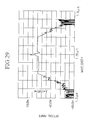
- a reference 1 (a Japanese Patent Application, First Publication, Hei 8-234249, "Coherent white pulse source") disclosed a white pulse source using a single-mode optical fiber as the nonlinear optical medium, and reported a production of white pulses having an excellent spectral flatness over a wide range of wavelengths as illustrated in Figure 24. Based on a supposition that such white pulses were produced because of the choice of a low dispersion slope of the waveguided nonlinear optical medium, values of the dispersion slope which is defined as the first derivative of chromatic dispersion with respect to wavelength and magnitudes of dispersion are specified.
- Figure 24 shows the spectrum of the pump pulse also.
- the reference 1 also disclosed that the bandwidth of the white pulse increases by using a waveguided nonlinear optical medium whose chromatic dispersion decreased with propagation distance z.
- white pulses are generated by a device to pump a waveguided nonlinear optical medium with optical gain (rare-earth doped optical fiber). This device is able to generate white pulses even when the power of pump pulses is low or the length of the waveguided nonlinear optical medium is short.
- references 1 and 2 specify only the first order term (dispersion slope) in the chromatic dispersion to wavelengths in the waveguided nonlinear optical medium.
- the results are associated mostly with doping effects in the waveguided nonlinear optical medium, and the manner of chromatic dispersion reduction is only minimally specified. Therefore, at the present time, a white pulse such as the one illustrated by the special curve in Figure 24 that satisfy both requirements of wide band-width and spectral flattening have not been reproduced in practice.
- White pulses generate via a two stage process: a spectral broadening stage caused by adiabatic soliton compression; and a rectangular-shape forming stage caused by soliton changing into dispersive waves.
- the result is a generation of a white pulse spectrum, showing flatness over a wide range of wavelength.
- Another object of the present invention is to provide a stable-output white pulse source to generate white pulses having stable output power and low noise characteristics.
- a white pulse source having a pump pulse generating section for producing pump pulses and a waveguided nonlinear optical medium for generating white pulses by being injected with the pump pulses, comprising a power stabilization section for controlling the optical power of pump pulses to be input into the waveguided nonlinear optical medium by reducing a noise component according to a relation of pump pulse power to noise coefficients generated in the course of a white pulse generation.
- the white pulse source of the present invention has been applied to produce white pulses having low noise and stable output power.
- Another object is to provide a low-noise optical pulse source to produce optical pulses having extremely low noise using the white pulse source of the present invention.
- an optical pulse source having a pump pulse generating section for producing pump pulses, a wave guided nonlinear optical medium for generating white pulses by being injected with the pump pulses, and a wavelength filter for filtering the white pulses to produce an optical pulse having a specific wavelength
- the optical pulse source comprising a noise reducing section for controlling the optical power of pump pulses to be input into the waveguided nonlinear optical medium by reducing a noise component in the specific wavelength according to a relation of pump pulse power to noise coefficients generated in the course of a white pulse generation.
- Figure 1 is a graph showing the first chromatic dispersion characteristic of a waveguided nonlinear optical medium with respect to wavelength for use in a equalized-output white optical pulse source.
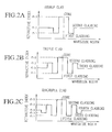
- Figures 2A ⁇ 2C are graphs showing a refractive index profiles of the waveguided nonlinear optical medium.
- Figure 3 is a graph showing a spectrum of pump pulses input into the waveguided nonlinear optical medium.
- Figure 4 is a graph showing a spectrum of white pulses generated by the waveguided nonlinear optical medium having the first chromatic dispersion characteristics shown in Figure 1.
- Figure 5 is an example of the output spectrum from a waveguided noNlinear optical medium whose chromatic dispersion has two zero-dispersion wavelengths but does not decrease with propagation distance.
- Figure 6 is a graph showing how a white pulse spectrum evolves along a waveguided nonlinear optical medium having the first chromatic dispersion characteristics shown in Figure 1.
- Figure 7 is a graph showing an example of the dependence of the spectral width of the white pulse on the effective medium length L0.
- Figure 8 is a graph showing an example of the relation of the threshold value Lth of the effective medium length L0 for generating white pulses to the peak power of the pump pulses.
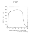
- Figure 9 is a graph showing an example of the dependence of the spectral width of the white pulse on chromatic dispersion D( ⁇ 0, 0) at the input end of the waveguided nonlinear optical medium.
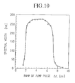
- Figure 10 is an example of the dependence of spectral width of the white pulse on the pulse width of the pump pulse.
- Figure 11 is an example of the dependence of the spectral width of the white pulse on the pump pulse width, in which chromatic dispersion D( ⁇ 0, 0) is a parameter.
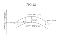
- Figure 12 is a graph showing a second chromatic dispersion characteristic of a waveguided nonlinear optical medium with respect to wavelength for use in a equalized-output white optical pulse source.
- Figures 13A ⁇ 13C are graphs showing a spectra of white pulses generated by the waveguided nonlinear optical medium having the chromatic dispersion characteristics shown in Figure 12 for different wavelength difference ⁇ .
- Figure 14 is a graph showing a third chromatic dispersion characteristic of a waveguided nonlinear optical medium with respect to wavelength for use in a equalized-output white optical pulse source.
- Figure 15 is a graph showing a spectrum of white pulses generated by the waveguided nonlinear optical medium having the chromatic dispersion characteristics shown in Figure 14.
- Figure 16 is a schematic configuration of a equalized-output white pulse source in Embodiment 2.
- Figure 17 is an example of a white pulse spectrum produced from a equalized-output white pulse source in Embodiment 2.
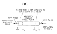
- Figure 18 is a schematic configuration of an equalized-output white pulse source in Embodiment 3.
- Figure 19 is a graph showing an example of the dependence of the white pulse spectral width on the effective medium length L0 of the waveguided nonlinear optical medium with gain.
- Figure 20 is a schematic configuration of an equalized-output white pulse source in Embodiment 4.
- Figure 21 is a schematic configuration of an equalized-output white pulse source in Embodiment 5.
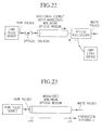
- Figure 22 is a schematic configuration of an equalized-output white pulse source in Embodiment 6.
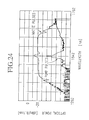
- Figure 23 is a schematic configuration of a conventional white pulse source.
- Figure 24 is an example of a spectrum produced by a white pulse source cited in reference 1.
- Figure 25 is a graph showing the chromatic dispersion characteristics of the waveguided nonlinear optical medium used in the white pulse source cited in reference 2.
- Figure 26 is an example of a spectrum produced by a white pulse source cited in reference 2.
- Figure 27 is a map showing a contour curves of spectral widths of output from the waveguided nonlinear optical medium with respect to chromatic dispersion at the input end D( ⁇ 0, 0) on the vertical axis and effective medium lengths L0 on the horizontal axis.
- Figure 28 is a map showing a contour curves of spectral widths of output from the waveguided nonlinear optical medium with Raman effect with respect to chromatic dispersion at the input end D( ⁇ 0, 0) on the vertical axis and effective medium lengths L0 on the horizontal axis.
- Figure 29 is a spectrum of white pulses generated from the waveguided nonlinear optical medium designed according to a third relation of wavelengths to chromatic dispersion.
- Figure 30 is a block diagram of the basic configuration of the stable-output white pulse source of the present invention.
- Figure 31 is a block diagram of a configuration of the stable-output white pulse source in Embodiment 1 in Section 2.
- Figure 32 is a schematic configuration of the experimental setup for measuring the noise coefficient.
- Figure 33 is an example of the measurement results of the noise coefficient depending on the peak power of pump pulses for different wavelengths.
- Figures 34A and 34B are a block diagrams of the stable-output white pulse source in Embodiment 2 in Section 2.
- Figure 35 is a block diagram of the stable-output white pulse source in Embodiment 3 in Section 2.
- Figure 36 is a block diagram of the stable-output white pulse source in Embodiment 4 in Section 2.
- Figure 37 is a block diagram of the stable-output white pulse source in Embodiment 5 in Section 2.
- Figure 38 is a block diagram of the stable-output white pulse source in Embodiment 6 in Section 2.
- Figure 39 is a block diagram of the stable-output white pulse source in Embodiment 7 in Section 2.
- Figure 40 is a block diagram of the stable-output white pulse source in Embodiment 8 in Section 2.
- Figure 41 is a block diagram of the stable-output white pulse source in Embodiment 9 in Section 2.
- Figure 42 is a block diagram of the stable-output white pulse source in Embodiment 10 in Section 2.
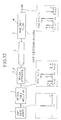
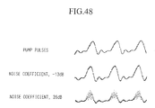
- Figure 43 is an example of noise components in a harmonically mode-locked laser as a pump pulse source.
- Figure 44 is another example of low-frequency noise components in a mode-locked laser as a pump pulse source.
- Figure 45 is a block diagram of the stable-output white pulse source in Embodiment 11 in Section 2.
- Figure 46 is a block diagram of a basic configuration of the low-noise pulse source of the present invention.
- Figure 47 is a block diagram of a configuration of the low-noise pulse source of the present invention in Embodiment 1 in Section 3.
- Figure 48 illustrates the dependence of intensity fluctuation in optical pulses filtered from white pulses for different noise coefficients.
- Figures 49A, 49B are block diagrams of the low-noise pulse source of Embodiment 2 in Section 3.
- Figure 50 is a block diagram of the low-noise pulse source of Embodiment 3 in Section 3.
- Figure 51 is a block diagram of the low-noise pulse source of Embodiment 4 in Section 3.
- Figure 52 is a block diagram of the low-noise pulse source of Embodiment 5 in Section 3.
- Figure 53 is a block diagram of the low-noise pulse source of Embodiment 6 in Section 3.
- Figure 54 is a block diagram of the low-noise pulse source of Embodiment 7 in Section 3.
- Figure 55 is a block diagram of the low-noise pulse source of Embodiment 8 in Section 3
- Figure 56 is a block diagram of the stable-output white pulse source in Embodiment 9 in Section 3.
- the white pulse source for generating white pulses by inputting pump pluses into the waveguided nonlinear optical medium will be presented under the following three sections dealing with white pulse sources of respective properties as defined below:
- the white pulse sources in this section are comprised by a pump pulse source for generating pump pulses having a center wavelength ⁇ 0, and the waveguided nonlinear optical medium (shortened to optical medium hereinbelow) having a length of L for generating white pulses by being injected with the pump pulses.
- the chromatic dispersion D( ⁇ , z) has a maximum value of D( ⁇ p(z), z) at a peak wavelength ⁇ p(z), and within a range of propagation distance z where D( ⁇ p(z), z) are positive, chromatic dispersion is zero (ps/nm/km) at two wavelengths ⁇ 1(z) and ⁇ 2(z).
- a white pulse evolves through a two-stage process: a spectral broadening stage due to adiabatic soliton compression and a stage of rectangular shaping and output power flattening caused by solitons changing into dispersive waves.
- a pump pulse injected into the optical meclium undergoes spectral broadening in the stage of adiabatic soliton compression within the propagation distance z where the chromatic dispersion D( ⁇ 0, z) of the optical medium is positive (anomalous dispersion) at the center wavelength ⁇ 0.
- the chromatic dispersion D( ⁇ 0, z) of the optical medium decreases with propagation distance z, and as the two zero-dispersion wavelengths, ⁇ 1(z) and ⁇ 2(z), approach the center wavelength ⁇ 0 of the pump pulse, although the both edges of the spectrum of the pulse being compressed enter into the negative (normal dispersion) dispersion region, the pulse being compressed as a whole retains soliton characteristics during spectral broadening stage.
- Figure 6 illustrates how a white pulse spectrum evolves with propagation distance z.
- the zero-dispersion wavelengths are indicated by broken lines in Figure 6, and, at the propagation distance L0, the two zero-dispersion wavelengths become coincident with the pump wavelength ⁇ 0.
- the spectrums of the pump pulses are indicated by (a) at the input end of the optical medium. As the two zero-dispersion wavelengths approaches the pump pulse wavelength, the spectrum progressively changes to a rectangular shape and, at the output end, a flattened spectrum is obtained as is shown in (e).
- the first embodiment of the white pulse source is comprised by a pump pulse source similar to the one shown in Figure 23 and a waveguided nonlinear optical medium (shortened to optical medium hereinbelow).
- the optical medium to be used in the white pulse source in the present invention is distinguished by a special characteristic of a chromatic dispersion with respect to wavelength and distance from the input end.
- Figure 1 illustrates a first characteristic of a chromatic dispersion with respect to wavelength and distance in the optical medium to be used as a white pulse source.
- the vertical axis and the horizontal axis represent chromatic dispersion in ps/nm/km and wavelength in nm.
- chromatic dispersion D( ⁇ , z) shows a maximum value D( ⁇ p(z), z) at a wavelength ⁇ p(z), and in the vicinity of the peak wavelength ⁇ p(z), the graph can be approximated by a quadratic function.
- ⁇ 0 is set equal to ⁇ p(z)
- the two wavelengths ⁇ 0 and ⁇ p(z) do not necessarily have to be equal, such that some difference ⁇ in wavelength can be allowed.
- chromatic dispersion D( ⁇ , z) decreases from positive value to negative value with the propagation distance z in the optical medium.
- chromatic dispersion D( ⁇ , z) has two zero-dispersion wavelengths ⁇ 1(z) and ⁇ 2(z), where ⁇ 1(z) ⁇ ⁇ 2(z).
- the chromatic dispersion D( ⁇ , z) is more than zero ps/nm/km (anomalous dispersion) when a wavelength ⁇ is greater than ⁇ 1(z) and less than ⁇ 2(z), and becomes less than zero ps/nm/km (normal dispersion) when a wavelength ⁇ is less than ⁇ 1(z) or more than ⁇ 2(z).
- the characteristic of a chromatic dispersion with respect to wavelength and distance in the optical medium for use in the white pulse source of the present invention is characterized by: (1) the chromatic dispersion D( ⁇ 0,z) at the pump wavelength ⁇ 0 decreases from a positive value to negative value with propagation distance z, and also (2) chromatic dispersion D( ⁇ 0, z) has a maximum value D( ⁇ p (z), z) and within the range of propagation clistance z where the maximum value is positive, there are two zero-dispersion wavelengths ⁇ 1(z) and ⁇ 2(z).
- Such characteristics of the chromatic dispersion discussed in the above paragraph can be realized in a double-clad, triple-clad or quadruple-clad waveguide having a refractive index profile such as those illustrated in Figures 2A ⁇ 2C.
- average refractive indexes, n0, n1 and n2 for a core, a first cladding and a second cladding, respectively are related by: n0 > n2 > n1.
- the relation among the refractive indexes is: n0 > n2 > n3 > n1.
- the relation is: n0 > n2 > n4 > n3 > n1.
- n0 > n2 > n4 > n3 n1.
- refractive index profiles are known, for example, as indicated in reference 4 (Kawakami et. al., "Optical fibers and fiber devices", Baifukan, pp114-115, 1966) or in reference 5 (L.G. Cohen et. al., "Low-loss quadruple-clad single-mode lightguides with dispersion value of less than 2 ps/nm/km over the 1.28 to 1.65 ⁇ m wavelength range", Electron. Lett., vol.18, p.1023, 1982).
- Chromatic dispersion along the longitudinal propagation direction in such waveguides can be altered by changing the core or cladding diameters, or by changing the refractive index of the core or the claddings.
- FIG 4 An example of the spectrum of a white pulse obtained by numerical analysis is shown in Figure 4, which is obtained by inputting a pump pulse whose spectrum is shown in Figure 3 into an optical medium having the characteristic of chromatic dispersion shown in Figure 1.
- a white pulse whose spectrum shows high flatness over a wide range of wavelength can be obtained by use of an optical medium fulfilling the requirements (1) and (2) in the optical medium mentioned above.
- the peak in the white pulse spectrum in Figure 4 corresponds to the pedestal of the pump pulse which were not converted to white pulse.
- D( ⁇ p(L0),L0) 0.
- Figure 7 shows an typical example of the dependence of the spectral width of the white pulse on the effective medium length L0 of the optical medium. As seen in this example, there is a particular effective medium length L0 in an optical medium at which the spectral width begins to increase suddenly. This is termed the threshold value Lth of the effective medium length L0.
- Figure 8 shows an typical example of the dependence of the threshold value Lth of the effective medium length L0 on the normalized peak power ⁇ P0 of the pump pulse
- P0 is a peak power in W and a nonlinear coefficient ⁇ is defined as ( ⁇ 0 nNL)/(c0 A);
- ⁇ 0 2 ⁇ c0/ ⁇ 0 is an angular frequency of the pump pulse and c0 is the speed of light in a vacuum;
- nNL is a nonlinear refractive index of the optical medium in m2/W;
- A is a mode field area in m2 of the optical medium at the center wavelength ⁇ 0.
- the peak power P0 a the pump pulse and the effective medium length L0 so as to satisfy a relation: ⁇ P0 L0 ⁇ 4.6, it is possible to generate white pulse having a wide spectral width.
- ⁇ P0 0.00775 m -1
- the medium length should be longer than 600 m.
- Figure 9 shows a typical example of the dependence of the spectral width of the white pulse on a chromatic dispersion D( ⁇ 0, 0) at the input end of a optical medium.
- the chromatic dispersion D( ⁇ 0, 0) to generate white pulse having a wide spectral width is found to have a lower limit (2 ps/nm/km) of D( ⁇ 0, 0) and an upper limit (27 ps/nm/km).
- Figure 10 shows a typical example of the dependence of the spectral width of the white pulse on the pulse width of a pump pulse.
- a pulse width (full width half maximum, FWHM) to generate white pulse having a wide spectral width is found to have a lower limit (2 ps) and an upper limit (8 ps).
- Figure 11 shows a typical example of the dependence of spectral width of the white pulse on the pulse width of a pump pulse and a chromatic dispersion D( ⁇ 0, 0) at the input end of a optical medium.
- a chromatic dispersion D( ⁇ 0, 0) is set higher, a lower and an upper limits for FWHM of pump pulse shift towards higher to generate white pulse having a wide spectral width.
- the chromatic dispersion D( ⁇ 0, 0) at the input end and the FWHM of the pump pulse ⁇ t of the pump pulse should satisfy the following expression: 0.05 ⁇ t 2 ⁇ D( ⁇ 0, 0) ⁇ 3.0 ⁇ t 2 . Also, when ⁇ P0 L0 ⁇ 3.5.
- the chromatic dispersion D( ⁇ 0, 0) at the input end and the FWHM of the pump pulse ⁇ t of the pump pulse should satisfy the following expression: 0.2 ⁇ t 2 ⁇ D( ⁇ 0, 0) ⁇ 1.2 ⁇ t 2
- ⁇ P0 0.00775 m -1
- L0 ⁇ 600 m and ⁇ t 4 ps and chromatic dispersion should satisfy a relation 2 ps/nm/km ⁇ D( ⁇ 0, 0) ⁇ 27 ps/nm/km.
- the spectral widths of the white pulse output from the optical medium are represented by a contour graph with respect to effective medium length L0 on the horizontal axis and chromatic dispersion D( ⁇ 0, 0) on the vertical axis as shown in Figure 27.
- the spacing between the contour curves corresponds to a spectral width of 25 nm.
- the requirements for the optical medium to generate white pulses are expressed by: L0 ⁇ 473/D( ⁇ 0, 0) + 374 - 1.8D( ⁇ 0, 0) + 0.34 D( ⁇ 0, 0) 2 where L0 is in meter and D( ⁇ 0, 0) is in ps/nm/km.
- Figure 28 shows a contour graph for spectral widths in a typical optical material, fused silica, with respect to effective medium length L0 on the horizontal axis and chromatic dispersion D( ⁇ 0, 0) on the vertical axis.
- the values of peak power P0 and the FWHM of a pump pulse ⁇ t were the same as those in Figure 27, respectively, at 0.5 W and 4 ps.
- the requirements to produce white pulses are expressed as: L0 ⁇ 426 / D( ⁇ 0, 0) + 308 - 1.7 D( ⁇ 0, 0) + 0.18 D( ⁇ 0, 0) 2 where L0 is in meter and D( ⁇ 0, 0) is in ps/nm/km. Threshold value for the effective medium length L0 to generate white pulses has been reduced compared with the results in Figure 27.
- Figure 12 shows a second characteristic of chromatic dispersion in the optical medium for use in a white pulse source of the present invention.
- a feature of the second dispersion characteristic is that the center wavelength ⁇ 0 and the peak wavelength ⁇ p(z) do not necessarily coincide with each other, but there is some tolerance for deviation in the wavelengths, represented by a wavelength differential ⁇ , according to the following expression: ⁇ p(L0) - ⁇ ⁇ ⁇ 0 ⁇ ⁇ p(L0) + ⁇ .
- the peak wavelength ⁇ p(L0) stayed at the same wavelength with decrease in the maximum dispersion D( ⁇ p(L0), z); however, it is not necessary that the peak wavelength ⁇ p(L0) remains unchanged with respect to the propagation distance z.
- the optical medium may allow some shift in the peak wavelength ⁇ p(L0) as the maximum dispersion D( ⁇ p(L0), z) decreases.
- This third dispersion characteristic is produced in practice when only the diameters of the core and the cladding(s) in the longitudinal direction are altered.
- the white pulse spectrum generated from a white pulse source having an optical medium of such dispersion characteristics is shown in Figure 15. It can be seen that the white pulses having high degree of flatness over a wide range of wavelengths are obtained, as in the case of a medium having the first or second characteristic of chromatic dispersion.
- Figure 29 shows another example of white pulse spectrum experimentally generated from an optical medium designed and manufactured according to the third dispersion characteristic.
- the optical meclium was a single-mode optical fiber which generated white pulses having a equalized spectrum over a spectral range in excess of 200 nm.
- the portion that does not contribute to white pulse generation is sometimes manufactured in addition to the portion that contributes to such a process.
- the optical medium is made so that the portion that contributes to white pulse generation are carried out in a range of propagation distance, L1 ⁇ z ⁇ L2, as illustrated in Figure 18.
- a white pulse source It is allowable to use an waveguided nonlinear optical medium with optical gain in a white pulse source.
- a white pulse source is able to generate white pulses even with low-power pump pulses that would not produce white pulses in a optical medium with no gain, or in a short length of optical medium.
- Figure 19 shows a dependence of the spectral width of the output white pulses on the effective medium length L0 in an optical medium with optical gain.
- White circles refer to the cases of optical medium having a gain of 0.01 dB/m and filled circles refer to the case of optical medium having a gain of 0.05 dB/m.
- the parameters of the pump pulse such as the peak power and pulse width, and chromatic dispersion D( ⁇ 0, 0) at the input end of the optical medium, were kept the same as those in the optical medium with no gain shown in Figure 7.
- the threshold, value Lth in the effective medium length L0 for optical medium with gain is shortened. Also, the effect of the optical medium with gain is equivalent to that of using a high power pump pulse according to a relation of the threshold value Lth to the peak power of pump pulse shown in Figure 8. In other words, an amplifying optical medium is able to generate white pulses even if the power of the pump pulse is low or the optical medium is short.
- Figure 20 is a schematic configuration of a white pulse source in Embodiment 4 comprised by pump pulse source and an amplifying optical medium represented by a semi-conductor amplifier and the like.
- FIG 21 is a schematic configuration of a white pulse source in Embodiment 5.
- the white pulse source is comprised by: a pump pulse source; a rare-earth-doped waveguided nonlinear optical medium; a pump source for generating pump light to cause a population inversion in the rare-earth-doped optical medium; and a wavelength-division optical multiplexer for multiplexing pump light and pump pulse to be input into the rare-earth-doped optical medium.
- FIG 22 is a schematic configuration of a white pulse source in Embodiment 6.
- the white pulse source is comprised by: a pump pulse source; a rare-earth-doped waveguided nonlinear optical medium; a pump source for generating pump light to cause a population inversion in the rare-earth-doped optical medium; and a wavelength-division optical multiplexer for inputting pump light into an output end of the rare-earth-doped optical medium; and an optical isolator to prevent the pump light which has propagated backward the rare-earth-doped optical medium to be input into the pump pulse source or to prevent the optical medium to oscillate like a laser.
- Embodiment 5 forward pumping configuration
- Embodiment 6 backward pumping configuration
- the rare-earth-doped optical medium with an optical medium to produce Raman amplification, and input the pump light into such a Raman gain optical medium.
- amplification action can be stabilized by providing an optical isolating means to prevent reflection of light back into the pump pulse source or the optical medium which causes laser oscillation in the optical medium.
- the peak observed in the white pulse spectrum at the center wavelength ⁇ 0 of the pump pulse corresponds to the pedestal of the pump pulse which did not convert to white pulses.
- the present white pulse source is characterized by: 1) having an optical medium in which the chromatic dispersion of pump pulses at the center wavelength ⁇ 0 diminishes from a positive value to a vicinity of zero ps/nm/km in the direction of propagation of the pump pulse; and 2) the chromatic dispersion characteristic has a maximum value when chromatic dispersion at wavelength ⁇ 0 is in the vicinity of zero ps/nm/km, and has two zero-dispersion wavelengths when the maximum value is positive.
- This structure prompts the spectrum of the input pump pulses to be broadened through soliton compression and to become rectangular and flat through a process in which a soliton pulse changes into a dispersive wave.
- white pulses can be produced under less restrictive conditions of lower power of pump pulse or shorter length of optical medium.
- Section 2 Stable-output White Pulse Sources
- the white pulse sources in this sections produce white pulses with low noise by controlling the pump pulse power to reduce the noise coefficient in the course of the white pulse generation, according to a relation of noise coefficient to the pump pulse power.
- the noise coefficient in white pulse generation and the pump pulse power into the optical medium will be explained.
- the noise coefficient is defined as a ratio of power fluctuation components included in the white pulses (wavelength components) generated from the optical medium to power fluctuation components included in the pump pulse.
- FIG 32 is a schematic configuration for determining the noise coefficient in white pulse generation.
- the pump pulse source 1 generates pump pulses at a repetition frequency f0. This pump pulse is superimposed with a power fluctuation component (frequency ⁇ f, modulation index M in ) in an optical power modulator 4, and is input into the optical medium 2 at a given optical power through an optical attenuator 5.
- the white pulse output from the optical medium 2 is filtered through a wavelength filter 3
- the filtered white pulse contains a fluctuation component (modulation index M out ).
- a noise coefficient for each wavelength component in a white pulse is obtained as a ratio, M out /M in , of the output modulation index M out to the input modulation index M in .
- the modulation index M in is defined as a ratio b/a, where b is the fluctuation component at frequencies f0 ⁇ ⁇ f and a is the carrier component at repetition frequency f0, and M out is defined as a ratio d/c, where d is the fluctuation component at frequencies f0 ⁇ ⁇ f and c is the carrier component at repetition frequency f0.
- Figure 33 is an example of the measurement results of noise coefficient in the white pulses to peak power of pump pulse obtained by the arrangement in Figure 32.
- the values shown in Figure 33 are actual measurements of the noise coefficients obtained by filtering the white pulses at different wavelengths.
- the center wavelength of the pump pulse is 1535 nm.
- the relation of the noise coefficient to the pump pulse power is dependent on the pulse width of the pump pulse and the chromatic dispersion characteristics in the optical medium, but commonly, the plots of the noise coefficient to the pump pulse power show the following features.
- the noise coefficient shows local minima with respect to pump pulse power, and the pump pulse powers where the noise coefficient has local minima shift upwards as the wavelength of the filtered white pulse shifts further from the pump wavelength.
- the noise coefficient has local minima at around 2.25 and 2.45 W, but for a wavelength 1476.92 nm (squares), it has the corresponding local minima at around 2.35 and 2.51 W. It was also observed that the higher the pump pulse power, the smaller the noise coefficient as a whole for each wavelength component.
- the noise coefficient When the noise coefficient is higher than 0 dB, power fluctuations in the pump pulse are amplified and transferred to the wavelength components in the white pulse, therefore, the waveform of the white pulse becomes distorted and the signal/noise ratio is degraded. If the noise coefficient is less than 0 dB, power fluctuation in the pump pulse are suppressed and barely transferred to the wavelength components in the white pulses, therefore, the waveform is not distorted and the signal/noise ratio is rather improved.
- Figure 30 is a schematic configuration of a stable-output white pulse source which inputs pump pulses generated in a pump pulse generation section 51 into the optical medium 2, and a stabilization section 50 is further provided to stabilize the optical power of white pulses output from the optical medium 2.
- the stabilization section 50 is provided with a function to control the optical power of pump pulse to be input into the optical medium 2 to reduce the noise component in the output white pulses according to the relation of the noise coefficient of the white pulses generated in the optical medium 2 to optical power of the pump pulses. Also, an optical branching section 6 is provided before the input end, or after the output end or on both ends of the optical medium 2 for the purpose of monitoring the optical power by the stabilization section 50 to obtain noise coefficients. The stabilization section 50 stabilizes the output power of the white pulses by controlling the pump pulse generation section 51 according to the noise coefficient thus obtained, thereby reducing the noise in the white pulses.
- Figure 31 shows a stable-output white pulse source of Embodiment 1.
- the pump pulse generation section 51 shown in Figure 30 is comprised by: a pump pulse source 1 which is capable of adjusting the output power; and the stabilization section 50 shown in Figure 30 is comprised by an optical power measuring section 7 to monitor the optical power of pump pulses through a branching section 6 before the input end of the optical medium 2, and an optical power control section 8 to control the output power from the pump pulse source 1 so as to adjust the optical power of the pump pulses input into the optical medium 2 to be at a target value.
- the relation of the noise coefficient to the pump pulse power is pre-determined, and the target value is selected to reduce the noise in the white pulses according to the pre-determined relation.
- the pump pulse power is adjusted to be in the vicinity of 2.25 or 2.45 W to reduce the noise coefficient at wavelength 1505.03 nm to its lowest value.
- the pump pulse power is adjusted to be in the vicinity of 2.31 or 2.49 W; and for 1476.92 nm wavelength, the power is adjusted to be 2.35 or 2.51 W.
- the pump pulse power is adjusted to be about 2.5 W.
- Optical power control section 8 adjusts the pump pulse power to be a target value by comparing the target value with the power level monitored by the optical power measuring section 7 and feeding-back any difference to the pump pulse generation section 51.
- the pump pulse generation section 51 is comprised by a pump pulse source whose output power is adjustable, but in Embodiment 2, the pump pulse generation section 51 is comprised by a pump pulse source and an in-line optical power adjusting section which controls the optical power of pump pulses to be input into the optical medium 2.
- Figure 34A, 34B show schematic configurations of a second embodiment of the stable-output white pulse source.
- Figure 34A shows a feed-back scheme and
- Figure 34B shows a feed-forward scheme.
- the stabilization section 50 is comprised by an optical power measuring section 7 and an optical power control section 8.
- Pump pulse generated in the pump pulse source 1 is input through the optical power adjusting section 9 into the optical medium 2 which outputs white pulses.
- the optical power of the pump pulses is monitored by the optical power measuring section 7 through the optical branching section 6 disposed on the fore- or aft-stage of the optical power adjusting section 9.
- the optical power control section 8 controls the power adjusting section 9 to minimize the difference between a optical power of pump pulses monitored by the power measuring section 7 and a target value so that the pump pulse power input into the optical medium 2 is at the target value.
- the optical power adjusting section 9 may use either or both of optical amplifying device or optical attenuating device.
- Embodiments 3 to 8 This section describes Embodiments 3 to 8 in Section 2.
- the relation of noise coefficient to pump pulse power was pre-determined and a target value of pump pulse power was selected to reduce the noise coefficient.
- Embodiments S2E3 ⁇ S2E8 fluctuation components are deliberately superimposed on the pump pulses and the noise coefficient is measured in real-time, so that the pump pulse power can be feedback-controlled according to the measured noise coefficient.
- Figure 35 shows Embodiment 3 in Section 2.
- the pump pulse generation section 51 shown in Figure 30 is comprised by: a pump pulse source 1 which is capable of adjusting the output power and an optical power modulator 4; and the stabilization section 50 shown in Figure 30 is comprised by an optical power control section 11 and a modulation component measuring section 10.
- Pump pulses generated in the pump pulse source 1 are input through the optical power modulator 4 to superimpose a power fluctuation of a given level of modulation index M in into the optical medium 2 which generates white pulses.
- the modulation index M out contained in the output white pulses is measured by the modulation component measuring section 10 through an optical branching section 6 after the output end of the optical medium 2.
- Optical power control section 11 figures out a noise coefficient as a ratio M out /M in , and controls the pump pulse source 1 to minimize the noise coefficient related to pump pulse power.
- Figure 36 shows Embodiment 4 in Section 2.
- the pump pulse generation section 51 shown in Figure 30 is comprised by: a pump pulse source 1, an in-line optical power adjusting section 9, and an optical power modulator 4; and the stabilization section 50 shown in Figure 30 is comprised by an optical power control section 11 and a modulation component measuring section 10.
- Pump pulses output from the pump pulse source 1 are input through the optical power modulator 4 to superimpose a power fluctuation of a given level of modulation index M in and are then input through an optical power adjusting section 9, into the optical medium 2 which generates white pulses.
- the modulation index M out contained in the output white pulses is measured by monitoring the optical power of the white pulse in the modulation component measuring section 10 through an optical branching section 6 after the output end of the optical medium 2.
- Optical power control section 11 figures out a noise coefficient as a ratio M out /M in , and controls the optical power adjusting section 9 to minimize the noise coefficient related to pump pulse power.
- the optical power control section 9 may use either or both of optical amplifier device or optical attenuator device.
- the optical power adjusting section 9 is located before the optical power modulation device 4, but it is permissible to locate the optical power modulation device 4 after the optical power adjusting section.
- the modulation index M in to be superimposed on the pump pulse at the input side of the optical medium 2 is made constant.
- the pump pulse power is adjusted according to the modulation index M out because the noise coefficient corresponds to the modulation index M out contained in the white pulses.
- Figure 37 shows Embodiment 5 in Section 2.
- the pump pulse generation section 51 shown in Figure 30 is comprised by: a pump pulse source 1 which is capable of adjusting the output power and an optical power modulator 4; and the stabilization section 50 shown in Figure 30 is comprised by an optical power control section 11 and a modulation component measuring section 10.
- Pump pulses generated in the pump pulse source 1 are input through the optical power modulator 4 to superimpose a power fluctuation of a given level of modulation index M in , and into the optical medium 2 which generates white pulses.
- the modulation index M out contained in the output white pulses is measured by monitoring the optical power of the white pulse in the modulation component measuring section 10 through an optical branching section 6 after the output end of the optical medium 2.
- Optical power control section 11 controls the pump pulse source 1 to minimize the modulation index M out of the white pulses being measured by the modulation component measuring section 10, and adjusts the pump pulse power to be input into the optical medium 2.
- Figure 38 shows Embodiment 6 in Section 2.
- the pump pulse generation section 51 shown in Figure 30 is comprised by: a pump pulse source 1, an in-line optical power adjusting section 9, and an optical power modulator 4; and the stabilization section 50 shown in Figure 30 is comprised by an optical power control section 11 and a modulation component measuring section 10.
- Pump pulses generated in the pump pulse source 1 are input through the optical power modulator 4 to superimpose a power fluctuation of a given level of modulation index M in and are then input through the optical power adjusting section 9, into the optical medium 2 which generates white pulses.
- the modulation index M out contained in the output white pulses is measured by moninoring the optical power of the white pulse in the modulation component measuring section 10 through an optical branching section 6 after the output end of the optical medium 2.
- Optical power control section 11 controls the optical power adjusting section 9 to minimize the modulation index M out of the white pulses being measured by the modulation component measuring section 10, and adjusts the pump pulse power to be input into the optical medium 2.
- the optical power control section 9 may use either or both of optical amplifying device or optical attenuating device.
- the optical power adjusting section 9 is located before the optical power modulation device 4, but it is permissible to locate the optical power modulation device 4 after the optical power adjusting section.
- Embodiments 3 ⁇ 6 utilized modulation index M out of the white pulses, i.e., overall values of the modulation index for all wavelengths are being measured.
- the pump pulse power is controlled so as to achieve overall low noise in the white pulses.
- Embodiments 7 and 8 presented in the following are directed to controlling the pump pulse power to minimize the noise in a particular wavelength component in the white pulse.
- the configurations correspond to those used in Embodiments 5 and 6, but this technique can be applied equally well to the configurations in Embodiments 3 and 4.
- Figure 39 shows Embodiment 7 in Section 2.
- the pump pulse generation section 51 shown in Figure 30 is comprised by: a pump pulse source 1 which is capable of adjusting the output power and an optical power modulator 4; and the stabilization section 50 shown in Figure 30 is comprised by an optical power control section 11, a modulation component measuring section 10 and a wavelength filter 3.
- the feature of this embodiment is that white pulses split in the optical branching section 6 (refer to Figure 37) is monitored by the modulation component measuring section 10 through a wavelength filter 3 having a specific wavelength band.
- the modulation component measuring section 10 measures a modulation component for the wavelength band transmitted through the optical filter 3, therefore, the noise component in the white pulses is minimized particularly in the wavelength band designated by the wavelength filter 3.
- Figure 40 shows Embodiment 8 in Section 2.
- the pump pulse generation section 51 shown in Figure 30 is comprised by: a pump pulse source 1, an in-line optical power adjusting section 9, and an optical power modulator 4; and the stabilization section 50 shown in Figure 30 is comprised by an optical power control section 11, a modulation component measuring section 10 and a wavelength filter 3.
- the feature of this embodiment is that white pulses split in the optical branching section 6 (refer to Figure 38) is monitored by the modulation component measuring section 10 through a wavelength filter 3 having a specific wavelength band.
- the modulation component measuring section 10 measures a modulation component for the wavelength band transmitted through the optical filter 3, therefore, the noise component in the white pulses is minimized particularly in the wavelength band designated by the wavelength filter 3.
- Figure 40 shows the optical power adjusting section after the optical power modulator 4, but it can be placed before the modulator 4.
- the section presents Embodiments 9 and 10 in Section 2.
- Embodiments 9, 10 directly measure the noise components in white pulses to control the pump pulse power and to reduce the noise components.
- the noise components originate from the pump pulse source, and are transferred from the pump pulses to the white pulses in the course of the white pulse generation.
- Figure 41 shows Embodiment 9 in Section 2.
- the pump pulse generation section 51 shown in Figure 30 is comprised by: a pump pulse source 1 which is capable of adjusting the output power; and the stabilization section 50 shown in Figure 30 is comprised by an optical power control section 13 and a noise component measuring section 12.
- Pump pulses generated in the pump pulse source 1 are input into the optical medium 2 which generates white pulses.
- the noise components contained in the output white pulses is measured by monitoring the optical power of the white pulse in the noise component measuring section 12 through an optical branching section 6 after the output end of the optical medium 2.
- Optical power control section 13 controls the pump pulse source 1 to minimize the noise component of the white pulses being measured by the noise component measuring section 12, and adjusts the pump pulse power to be input into the optical medium 2.
- Figure 42 shows Embodiment 10 in Section 2.
- the pump pulse generation section 51 shown in Figure 30 is comprised by: a pump pulse source 1, and an in-line optical power adjusting section 9; and the stabilization section 50 shown in Figure 30 is comprised by an optical power control section 13 and a noise component measuring section 12.
- Pump pulses generated in the pump pulse source 1 are input, through the optical power adjusting section 9, into the optical medium 2 which generates white pulses.
- the noise components contained in the output white pulses is measured by monitoring the optical power of the white pulse in the noise component measuring section 12 through an optical branching section 6 after the output end of the optical medium 2.
- Optical power control section 13 controls the optical power adjusting section 9 to minimize the noise component of the white pulses being measured by the noise component measuring section 10, and adjusts the pump pulse power to be input into the optical medium 2.
- either or both optical amplifier and optical attenuator may be used in the optical power control section 9.
- Embodiments 7 and 8 it is permissible to apply the configurations used for Embodiments 7 and 8 to Embodiments 9, 10 to control the noise in the white pulses, by disposing a wavelength filter 3 between the optical branching section 6 after the output end of the optical medium 2 and the noise component measuring section 12.
- Figure 45 shows Embodiment 11 in Section 2 which accepts external pump pulses through a pump pulse input section 55 into the optical medium 2, and a stabilization section 50 is provided to stabilize the optical power of white pulses output from the optical medium 2.
- the stabilization section 50 is provided with a function to control the pump pulse input section 55 to adjust optical power of pump pulse to be input into the optical medium 2 to reduce the noise component in the output white pulses according to the relation of the noise coefficient of the white pulses generated in the optical medium 2 to optical power of the pump pulses.
- Figure 43 shows an example of measuring the noise components output from a white pulse source utilizing a harmonically mode-locked pulse laser as a pump pulse source.
- Figure 44 shows an example of measuring the low-frequency noise components output from a white pulse source.
- This method is valid when using a mode-locked pulse laser as the pump pulse source 1.
- Spectral components at a relaxation oscillation frequency from such laser source contribute as low-frequency intensity noise, which can be monitored and used as a feedback flag to reduce its value.
- a white pulse source which generates a equalized spectrum over a wide bandwidth, the wavelength-dependency of the spectrum of the output white pulses can be reduced considerably.
- a white pulse source as explained in Section 1, can be realized by using a waveguided nonlinear optical medium 2 that exhibits a chromatic dispersion characteristics shown in Figures 1, 13 and 15.
- the optical medium 2 should satisfy the requirements that: (1) the chromatic dispersion at the wavelength of the pump pulse decreases from positive value to less than zero in the propagation direction of the pump pulse; and (2) over the entire or partial range of propagation distance in the optical medium, the chromatic dispersion characteristic shows two zero-dispersion wavelengths, both of which approach the wavelength of the pump pulse with the propagation distance from the input end.
- Figure 1 is an example of the chromatic dispersion characteristic where the center wavelength ⁇ 0 of pump pulses coincides with the peak wavelength of the chromatic dispersion
- Figure 12 is an example of the chromatic dispersion characteristic where the center wavelength ⁇ 0 of pump pulses does not necessarily coincide with the peak wavelength of the chromatic dispersion
- Figure 14 is an example in which the peak wavelength of the chromatic dispersion varies along the propagation direction.
- a stable-output white pulse source will be able to generate white pulses having a equalized-output optical power over a wide bandwidth.
- the present stable-output white pulse source enables to minimize noise in the output white pulses by controlling the optical power of pump pulses input into the optical medium, thereby generating low-noise white pulses that are unaffected by the power fluctuations occurring in the pump pulses.
- a low-noise white pulse source filters out a specific wavelength from the output white pulses, and minimizes the noise coefficient at the specific wavelength by controlling the pump pulse power according to a relation of the noise coefficient to the pump pulse power in the white pulse generation.
- the noise coefficient in the white pulse generation depends sensitively on the optical power of pump pulses, and there is a specific values of pump pulse power at which the noise coefficient is reduced to less than 0 dB.
- the pump pulse powers where the noise coefficient has local minima shift upwards as the wavelength of the filtered white pulse shifts further from the pump wavelength. For example, at a wavelength 1505.03 nm (indicated by circles), the noise coefficient has local minima at around 2.25 and 2.45 W, but for a wavelength 1476.92 nm (squares), it has the corresponding local minima at around 2.35 and 2.51 W.
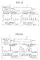
- the signal to noise ratio of optical pulses obtained by filtering the white pulses at a specific wavelength is given by a product of the noise coefficient and the signal to noise ratio of the pump pulse, therefore, the level of the noise coefficient affects the purity of the optical pulses obtained by filtering the white pulses at a specific wavelength, as illustrated in Figure 48.
- the level of the noise coefficient is higher than 0 dB (35 dB in Figure 48)
- the power fluctuation in the pump pulse is amplified and transferred onto the white pulses, so that the waveform of the optical pulse obtained by filtering from the white pulses is also seriously degraded.
- the level of the noise coefficient is less than 0 dB (-13 dB in Figure 48)
- the power fluctuation occurring in the pump pulse is suppressed and is barely transferred onto the white pulses so that the waveform is not degraded and may even be improved. It follows that, by controlling the pump pulse power so that the noise coefficient at a specific wavelength will be less than 0 dB, according to a relation of the noise coefficient to pump pulse power, it is possible to generate optical pulses having a lower noise level than that in the pump pulses.
- the low-noise pulse sources will be explained in detail in the following.
- Figure 46 is a schematic configuration of a low-noise-output white pulse source in which pump pulses generated in a pump pulse generation section 61 are input into the optical medium 2, and white pulses generated in the optical medium 2 are filtered through a wavelength filter 3 to output an optical pulse of a specific wavelength.
- a noise reduction section 60 is further provided to minimize the noise components in the output pulses of the wavelength filter 3.
- the noise reduction section 60 is provided with a function to control the optical power of pump pulse to be input into the optical medium 2, according to a relation of noise coefficient to pump pulse power, so as to minimize the noise coefficient to less than 0 dB.
- An optical branching section 6 is provided either before the input end of the optical medium 2 or after the wavelength filter 3 or at both ends, for the purpose of monitoring the optical power by the noise reduction section 60 to obtain a noise coefficient.
- the noise reduction section 60 controls the pump pulse generation section 61 accorcling to the noise coefficient thus obtained, thereby reducing the noise in the output pulses from the wavelength filter 3.
- Figure 47 is a schematic configuration of the low-noise pulse source of Embodiment 1 in Section 3.
- the pump pulse generation section 61 shown in Figure 46 is comprised by: a pump pulse source 1 which is capable of adjusting the output power; and the noise reduction section 60 shown in Figure 46 is comprised by an optical power measuring section 7 to monitor the optical power of pump pulses through a branching section 6 before the input end of the optical medium 2, and an optical power control section 8 to control the output power from the pump pulse source 1 so as to adjust the optical power of the pump pulses input into the optical medium 2 to be at a target value.
- the relation of the noise coefficient to the pump pulse power is pre-determined, and the target value is selected to reduce the noise coefficient for the specific wavelength of the wavelength filter 3, at less than 0 dB according to the pre-determined relation.
- the pump pulse power is adjusted to be in the vicinity of 2.25 or 2.45 W to minimize the noise coefficient to less than 0 dB at a wavelength of 1505.03 nm.
- the pump pulse power is adjusted to be in the vicinity of 2.31 or 2.49 W; and at a wavelength of 1476.92 nm, the power is adjusted to be 2.35 or 2.51 W.
- Optical power control section 8 adjusts the pump pulse power to be a selected target value by comparing the target value with the power level monitored by the optical power measuring section 7 and feeding-back any difference to the pump pulse source 1.
- pump pulse generation section 61 was comprised by a pump pulse source whose output power is adjustable, but in Embodiment 2, pump pulse generation section 61 is comprised by a pump pulse source and an in-line optical power adjusting section which controls the pump pulse power to be input into the optical medium 2.
- Figure 49 is a schematic configuration of the low-noise optical pulse source of Embodiment 2 in Section 3.
- Figure 49A shows a feed-back scheme and
- Figure 49B shows a feed-forward scheme.
- the stabilization section 60 is comprised by an optical power measuring section 7 and an optical power control section 8.
- Pump pulses generated in the pump pulse source 1 are input, through the optical power adjusting section 9, into the optical medium 2, and the output white pulses are filtered by a wavelength filter 3 to output optical pulses of a specific wavelength.
- the optical power of pump pulses is monitored by the optical power measuring section 7 through the optical branching section 6 disposed on the fore- or aft-stage of the optical power adjusting section 9.
- the optical power control section 8 controls the optical power adjusting section 9 to minimize the difference between the optical power of pump pulses monitored by the power measuring section 7 and a target value to adjust the pump pulse power into the optical medium 2 at the target value.
- the optical power control section 9 may be represented by either or both of optical amplifier and optical attenuator.
- Embodiments 1 and 2 were based on an approach of pre-determining a relation of the noise coefficient to pump pulse power, and the pump pulse power was controlled so that the noise coefficient at the wavelength specified by a wavelength filter 3 is minimized to less than 0 dB.
- the following Embodiments 3 ⁇ 6 fluctuation components are deliberately superimposed on the pump pulses and the noise coefficient depending on pump pulse power is measured in real-time, so that the pump pulse power can be feedback-controlled according to the measured noise coefficient.
- Figure 50 shows Embodiment 3 in Section 3.
- the pump pulse generation section 61 shown in Figure 46 is comprised by: a pump pulse source 1 which is capable of adjusting the output power and an optical power modulator 4; and the noise reduction section 60 shown in Figure 46 is comprised by an optical power control section 11 and a modulation component measuring section 10.
- Pump pulses generated in the pump pulse source 1 are input through the optical power modulator 4 to superimpose a power fluctuation of a given level of modulation index M in into the optical medium 2 which generates white pulses which are filtered through a wavelength filter 3 to produce optical pulses of a specific wavelength.
- the modulation index M out contained in the output pulses from the wavelength filter 3 is measured by the modulation component measuring section 10 through an optical branching section 6 disposed after the output end of the wavelength filter 3.
- Optical power control section 11 figures out a noise coefficient as a ratio M out /M in , and controls the pump pulse source 1 so as to minimize the noise coefficient related to pump pulse power.
- Figure 51 shows Embodiment 4 in Section 3.
- the pump pulse generation section 61 shown in Figure 46 is comprised by: a pump pulse source 1, an in-line optical power adjusting section 9, and an optical power modulator 4; and the noise reduction section 60 shown in Figure 46 is comprised by an optical power control section 11 and a modulation component measuring section 10.
- Pump pulses generated in the pump pulse source 1 are input through the optical power modulator 4 to superimpose a power fluctuation of a given level of modulation index M in and are then input through an optical power adjusting section 9, into the optical medium 2 which generates white pulses which are filtered through a wavelength filter 3 to produce optical pulses of a specific wavelength.
- the modulation index M out contained in the output pulses from the wavelength filter 3 is measured by the modulation component measuring section 10 through an optical branching section 6 disposed after the output end of the wavelength filter 3.
- Optical power control section 11 figures out a noise coefficient as a ratio M out /M in , and controls the optical power adjusting section 9 so as to minimize the noise coefficient related to pump pulse power.
- the optical power control section 9 may use either or both of optical amplifying device or optical attenuating device.
- the optical power adjusting section is provided after the optical power modulation device 4, but it may be provided before the device 4.
- Embodiments 5 and 6 controlled the pump pulse power according to M out contained in the white pulses, because for a constant value of the modulation index Min superimposed on the pump pulse, the noise coefficient is equivalent to modulation index M out .
- Figure 52 shows Embodiment 5 in Section 3.
- the pump pulse generation section 61 shown in Figure 46 is comprised by: a pump pulse source 1 which is capable of adjusting the output power and an optical power modulator 4; and the noise reduction section 60 shown in Figure 46 is comprised by an optical power control section 11 and a modulation component measuring section 10.
- Pump pulses generated in the pump pulse source 1 are input through the optical power modulator 4 to superimpose a power fluctuation of a given level of modulation index M in and are then input into the optical medium 2 which generates white pulses which are filtered through a wavelength filter 3 to produce optical pulses of a specific wavelength.
- the modulation index M out contained in the output pulses from the wavelength filter 3 is measured by the modulation component measuring section 10 through an optical branching section 6 disposed after the output end of the wavelength filter 3.
- Optical power control section 11 controls the pump pulse source 1 so as to minimize the modulation index M out equivalent to noise coefficient related to pump pulse power.
- Figure 53 shows Embodiment 6 in Section 3.
- the pump pulse generation section 61 shown in Figure 46 is comprised by: a pump pulse source 1, an in-line optical power adjusting section 9, and an optical power modulator 4; and the noise reduction section 60 shown in Figure 46 is comprised by an optical power control section 11 and a modulation component measuring section 10.
- Pump pulses generated in the pump pulse source 1 are input through the optical power modulator 4 to superimpose a power fluctuation of a given level of modulation index Min and are then input through an optical power adjusting section 9, into the optical medium 2 which generates white pulses which are filtered through a wavelength filter 3 to produce optical pulses of a specific wavelength.
- the modulation index M out contained in the output pulses from the wavelength filter 3 is measured by the modulation component measuring section 10 through an optical branching section 6 disposed after the output end of the wavelength filter 3.
- Optical power control section 11 controls the optical power adjusting section 9 so as to minimize the modulation index M out equivalent to noise coefficient related to pump pulse power.
- the optical power control section 9 may use either or both of optical amplifying device or optical attenuating device.
- the optical power adjusting section is provided after the optical power modulation device 4, but it may be provided before the device 4.
- the section presents Embodiments 7 and 8 in Section 3.
- Embodiments 7, 8 are based on the direct measurement and feedback control of noise components in an optical pulse obtained by filtering white pulses with a wavelength filter 3 to reduce the noise components.
- the noise components originate from the pump pulse source, and are transferred from the pump pulses to the white pulses in the course of the white pulse generation.
- Figure 54 shows Embodiment 7 in Section 3.
- the pump pulse generation section 61 shown in Figure 46 is comprised by: a pump pulse source 1 which is capable of adjusting the output power; and the noise reduction section 60 shown in Figure 46 is comprised by an optical power control section 13 and a noise component measuring section 12.
- Pump pulses generated in the pump pulse source 1 are input into the optical medium 2 to generate white pulses which are filtered through a wavelength filter 3 to produce optical pulses of a specific wavelength.
- the noise component contained in the output pulses from the wavelength filter 3 is measured by the noise component measuring section 12 through an optical branching section 6 disposed after the output end of the wavelength filter 3.
- the optical power control section 13 controls the pump pulse source 1 so as to minimize the noise components monitored by the noise component measuring section 12.
- Figure 55 shows Embodiment 8 in Section 3.
- the pump pulse generation section 61 shown in Figure 46 is comprised by: a pump pulse source 1 and an in-line optical power adjusting section 9; and the noise reduction section 60 shown in Figure 46 is comprised by an optical power control section 13 and a noise component measuring section 12.
- Pump pulses generated in the pump pulse source 1 are input through the optical power adjusting section 9, and are input into the optical medium 2 to generate optical pulses which are filtered through a wavelength filter 3 to produce optical pulses of a specific wavelength.
- the noise component contained in the output pulses from the wavelength filter 3 is measured by the noise component measuring section 12 through an optical branching section 6 disposed after the output end of the wavelength filter 3.
- the optical power control section 13 controls the optical power adjusting section 9 so as to minimize the noise components monitored by the noise component measuring section 12.
- either or both optical amplifier and optical attenuator may be used in the optical power control section 9.
- Figure 56 shows Embodiment 9 in Section 3 which accepts external pump pulses through a pump pulse input section 65 into the optical medium 2, and a noise reduction section 60 is provided to minimize the noise level in the optical pulses output from the wavelength filter 3.
- the noise reduction section 60 is provided with a function to control the pump pulse input section 65 to adjust optical power of pump pulse to be input into the optical medium 2 to reduce the noise level in the optical pulses output from the wavelength filter 3 even lower than that of the pump pulses according to the relation of the noise coefficient to pump pulse power.
- the optical medium 2 should again satisfy the same requirements as expressed previously, namely that: (1) the chromatic dispersion at the wavelength of the pump pulse decreases from positive value to less than zero in the propagation direction of the pump pulse; and (2) over the entire or partial range of propagation distance in the optical medium, the chromatic dispersion characteristic shows two zero-dispersion wavelengths, both of which approach the wavelength of the pump pulse with the propagation distance from the input end.
- the filter 3 may be a single wavelength, a multiple wavelengths or a variable wavelength filter.
- the modulation component or noise component to be monitored are the maximums in each wavelength band.
- the waveguided nonlinear optical medium 2 in each of the foregoing embodiments may be provided with polarization-maintaining property to generate polarization-maintaining white pulses so that optical waves having a stable polarization may be propagated in the optical medium. It follows that any filtered optical pulse would also have a stable optical polarization.
- the present low-noise pulse source minimizes the noise coefficient of the filtered optical pulse from the white pulses to less than 0 dB by controlling the optical power of pump pulses input into the optical medium, thereby generating optical pulses which have lower noise than that of the pump pulses.
Landscapes
- Physics & Mathematics (AREA)
- Nonlinear Science (AREA)
- General Physics & Mathematics (AREA)
- Optics & Photonics (AREA)
- Optical Modulation, Optical Deflection, Nonlinear Optics, Optical Demodulation, Optical Logic Elements (AREA)
- Optical Communication System (AREA)
Priority Applications (2)
| Application Number | Priority Date | Filing Date | Title |
|---|---|---|---|
| EP08154388.6A EP1970756A3 (fr) | 1997-06-18 | 1998-06-16 | Source d'impulsion optique et applications |
| EP08154374.6A EP1970755A3 (fr) | 1997-06-18 | 1998-06-16 | Source d'impulsion blanche et applications |
Applications Claiming Priority (12)
| Application Number | Priority Date | Filing Date | Title |
|---|---|---|---|
| JP161603/97 | 1997-06-18 | ||
| JP16160397 | 1997-06-18 | ||
| JP16160397 | 1997-06-18 | ||
| JP27459397 | 1997-10-07 | ||
| JP274593/97 | 1997-10-07 | ||
| JP27459397 | 1997-10-07 | ||
| JP08117698A JP3471213B2 (ja) | 1998-03-27 | 1998-03-27 | 低雑音パルス光源 |
| JP81177/98 | 1998-03-27 | ||
| JP81176/98 | 1998-03-27 | ||
| JP8117698 | 1998-03-27 | ||
| JP08117798A JP3471214B2 (ja) | 1998-03-27 | 1998-03-27 | 安定化白色パルス光源 |
| JP8117798 | 1998-03-27 |
Related Child Applications (2)
| Application Number | Title | Priority Date | Filing Date |
|---|---|---|---|
| EP08154388.6A Division EP1970756A3 (fr) | 1997-06-18 | 1998-06-16 | Source d'impulsion optique et applications |
| EP08154374.6A Division EP1970755A3 (fr) | 1997-06-18 | 1998-06-16 | Source d'impulsion blanche et applications |
Publications (2)
| Publication Number | Publication Date |
|---|---|
| EP0886174A2 true EP0886174A2 (fr) | 1998-12-23 |
| EP0886174A3 EP0886174A3 (fr) | 2001-03-07 |
Family
ID=27466533
Family Applications (3)
| Application Number | Title | Priority Date | Filing Date |
|---|---|---|---|
| EP08154388.6A Withdrawn EP1970756A3 (fr) | 1997-06-18 | 1998-06-16 | Source d'impulsion optique et applications |
| EP98401468A Ceased EP0886174A3 (fr) | 1997-06-18 | 1998-06-16 | Source d'impulsions de lumière blanche |
| EP08154374.6A Withdrawn EP1970755A3 (fr) | 1997-06-18 | 1998-06-16 | Source d'impulsion blanche et applications |
Family Applications Before (1)
| Application Number | Title | Priority Date | Filing Date |
|---|---|---|---|
| EP08154388.6A Withdrawn EP1970756A3 (fr) | 1997-06-18 | 1998-06-16 | Source d'impulsion optique et applications |
Family Applications After (1)
| Application Number | Title | Priority Date | Filing Date |
|---|---|---|---|
| EP08154374.6A Withdrawn EP1970755A3 (fr) | 1997-06-18 | 1998-06-16 | Source d'impulsion blanche et applications |
Country Status (2)
| Country | Link |
|---|---|
| US (1) | US5999548A (fr) |
| EP (3) | EP1970756A3 (fr) |
Cited By (8)
| Publication number | Priority date | Publication date | Assignee | Title |
|---|---|---|---|---|
| WO2001002904A1 (fr) * | 1999-06-30 | 2001-01-11 | The Furukawa Electric Co., Ltd. | Fibre optique |
| WO2005024482A1 (fr) * | 2003-09-05 | 2005-03-17 | Leica Microsystems Cms Gmbh | Source de lumiere comprenant plusieurs elements optiques microstructures |
| EP1855155A4 (fr) * | 2005-03-31 | 2008-04-02 | Sumitomo Electric Industries | Dispositif de source lumineuse |
| WO2008086996A1 (fr) * | 2007-01-16 | 2008-07-24 | Carl Zeiss Microimaging Gmbh | Dispositif d'éclairage à éléments optiques non linéaires pour produire une lumière laser dans un large domaine spectral avec une densité de puissance spectrale homogène |
| EP2045643A1 (fr) * | 2000-06-17 | 2009-04-08 | Leica Microsystems CMS GmbH | Agencement d'analyse de préparations microscopiques à l'aide d'un microscope scanner et dispositif d'éclairage pour un microscope scanner |
| WO2009095023A3 (fr) * | 2008-01-31 | 2010-03-11 | Nkt Photonics A/S | Système, dispositif et procédé de stabilisation de la puissance de sortie optique d'un système optique |
| CN111262634A (zh) * | 2018-11-30 | 2020-06-09 | 深圳市中兴微电子技术有限公司 | 色散估计方法、装置、接收机及存储介质 |
| US11474288B2 (en) * | 2017-05-04 | 2022-10-18 | Nkt Photonics A/S | Light system for supplying light |
Families Citing this family (59)
| Publication number | Priority date | Publication date | Assignee | Title |
|---|---|---|---|---|
| DE19527550A1 (de) * | 1995-07-27 | 1997-01-30 | Ficht Gmbh | Verfahren zum Steuern des Zündzeitpunktes bei Brennkraftmaschinen |
| US6115174A (en) | 1998-07-21 | 2000-09-05 | Corvis Corporation | Optical signal varying devices |
| US6344922B1 (en) * | 1998-07-21 | 2002-02-05 | Corvis Corporation | Optical signal varying devices |
| US6839522B2 (en) | 1998-07-21 | 2005-01-04 | Corvis Corporation | Optical signal varying devices, systems and methods |
| US6088152A (en) * | 1999-03-08 | 2000-07-11 | Lucent Technologies Inc. | Optical amplifier arranged to offset Raman gain |
| US6356383B1 (en) * | 1999-04-02 | 2002-03-12 | Corvis Corporation | Optical transmission systems including optical amplifiers apparatuses and methods |
| US6389186B1 (en) * | 1999-04-30 | 2002-05-14 | Lucent Technologies Inc. | Optical waveguide lasers and amplifiers with pump power monitors |
| US6587261B1 (en) * | 1999-05-24 | 2003-07-01 | Corvis Corporation | Optical transmission systems including optical amplifiers and methods of use therein |
| FR2800219B1 (fr) * | 1999-10-22 | 2006-06-30 | Algety Telecom | Procede d'ajustement de puissance pour un systeme de transmission optique a multiplexage en longueur d'onde |
| FR2800218B1 (fr) * | 1999-10-22 | 2002-01-11 | Algety Telecom | Systeme de transmission par fibre optique utilisant des impulsions rz |
| US6744792B1 (en) * | 1999-10-26 | 2004-06-01 | Nortel Networks, Ltd. | Wavelength stabilization of tunable lasers by current modulation |
| US6344925B1 (en) | 2000-03-03 | 2002-02-05 | Corvis Corporation | Optical systems and methods and optical amplifiers for use therein |
| DE20122782U1 (de) | 2000-06-17 | 2007-11-15 | Leica Microsystems Cms Gmbh | Beleuchtungseinrichtung |
| EP1164406B1 (fr) | 2000-06-17 | 2019-04-17 | Leica Microsystems CMS GmbH | Méthode et appareil pour illuminer un objet |
| DE20122783U1 (de) | 2000-06-17 | 2007-11-15 | Leica Microsystems Cms Gmbh | Anordnung zum Untersuchen mikroskopischer Präparate mit einem Scanmikroskop und Beleuchtungseinrichtung für ein Scanmikroskop |
| US6614815B1 (en) * | 2000-06-29 | 2003-09-02 | Lightwave Electronics | Blue laser based on interactions in fiber |
| DE10044690B4 (de) * | 2000-07-04 | 2006-05-11 | Eads Deutschland Gmbh | Verfahren und Vorrichtung zur Messung von Entfernungen und/oder Geschwindigkeiten durch Laserpulse |
| JP4372330B2 (ja) * | 2000-10-30 | 2009-11-25 | 富士通株式会社 | 分布型光増幅装置、光通信用の局および光通信システム |
| TWI226464B (en) * | 2000-11-13 | 2005-01-11 | Sumitomo Electric Industries | Optical fiber, non-linear optical fiber, optical amplifier using the same optical fiber, wavelength converter and optical fiber manufacture method |
| JP3904835B2 (ja) * | 2001-01-29 | 2007-04-11 | 株式会社日立製作所 | 光増幅器、光ファイバラマン光増幅器、及び光システム |
| US6654516B2 (en) * | 2001-08-20 | 2003-11-25 | Texas Instruments Incorporated | Optical system and method |
| US7272158B1 (en) * | 2005-02-15 | 2007-09-18 | Hrl Laboratories, Llc | Highly efficient waveguide pulsed THz electromagnetic radiation source and group-matched waveguide THz electromagnetic radiation source |
| FR2884623B1 (fr) * | 2005-04-15 | 2008-02-08 | Centre Nat Rech Scient | Dispositif de generation d'une lumiere polychromatique a spectre continu par excitation a une longueur d'onde |
| JP4816063B2 (ja) * | 2005-12-20 | 2011-11-16 | 住友電気工業株式会社 | 広帯域光源 |
| US8855316B2 (en) * | 2008-01-25 | 2014-10-07 | Qinetiq Limited | Quantum cryptography apparatus |
| GB0801395D0 (en) * | 2008-01-25 | 2008-03-05 | Qinetiq Ltd | Network having quantum key distribution |
| GB0801408D0 (en) * | 2008-01-25 | 2008-03-05 | Qinetiq Ltd | Multi-community network with quantum key distribution |
| GB0801492D0 (en) * | 2008-01-28 | 2008-03-05 | Qinetiq Ltd | Optical transmitters and receivers for quantum key distribution |
| GB0809038D0 (en) * | 2008-05-19 | 2008-06-25 | Qinetiq Ltd | Quantum key device |
| GB0809045D0 (en) * | 2008-05-19 | 2008-06-25 | Qinetiq Ltd | Quantum key distribution involving moveable key device |
| GB0809044D0 (en) | 2008-05-19 | 2008-06-25 | Qinetiq Ltd | Multiplexed QKD |
| GB0819665D0 (en) * | 2008-10-27 | 2008-12-03 | Qinetiq Ltd | Quantum key dsitribution |
| GB0822253D0 (en) * | 2008-12-05 | 2009-01-14 | Qinetiq Ltd | Method of establishing a quantum key for use between network nodes |
| GB0822356D0 (en) * | 2008-12-08 | 2009-01-14 | Qinetiq Ltd | Non-linear optical device |
| US8275263B1 (en) * | 2009-06-26 | 2012-09-25 | The Boeing Company | Multiplication of phase deviations |
| GB0917060D0 (en) | 2009-09-29 | 2009-11-11 | Qinetiq Ltd | Methods and apparatus for use in quantum key distribution |
| DE102009056092B4 (de) | 2009-11-30 | 2013-02-28 | PicoQuant GmbH. Unternehmen für optoelektronische Forschung und Entwicklung | Lichtquelle mit einem Diodenlaser |
| FR2966291A1 (fr) * | 2010-10-18 | 2012-04-20 | Centre Nat Rech Scient | Source laser nanoseconde |
| GB201020424D0 (en) | 2010-12-02 | 2011-01-19 | Qinetiq Ltd | Quantum key distribution |
| US9270080B1 (en) * | 2011-06-26 | 2016-02-23 | Fianium Ltd | Methods and apparatus pertaining to the use and generation of broadband light |
| EP2904671B1 (fr) * | 2012-10-05 | 2022-05-04 | David Welford | Systèmes et procédés pour amplifier la lumière |
| US10069271B2 (en) | 2014-06-02 | 2018-09-04 | Nlight, Inc. | Scalable high power fiber laser |
| US10310201B2 (en) | 2014-08-01 | 2019-06-04 | Nlight, Inc. | Back-reflection protection and monitoring in fiber and fiber-delivered lasers |
| US9837783B2 (en) | 2015-01-26 | 2017-12-05 | Nlight, Inc. | High-power, single-mode fiber sources |
| US10050404B2 (en) | 2015-03-26 | 2018-08-14 | Nlight, Inc. | Fiber source with cascaded gain stages and/or multimode delivery fiber with low splice loss |
| CN107924023B (zh) | 2015-07-08 | 2020-12-01 | 恩耐公司 | 具有用于增加的光束参数乘积的中心折射率受抑制的纤维 |
| US10768433B2 (en) | 2015-09-24 | 2020-09-08 | Nlight, Inc. | Beam parameter product (bpp) control by varying fiber-to-fiber angle |
| US11179807B2 (en) | 2015-11-23 | 2021-11-23 | Nlight, Inc. | Fine-scale temporal control for laser material processing |
| CN108367389B (zh) | 2015-11-23 | 2020-07-28 | 恩耐公司 | 激光加工方法和装置 |
| US10730785B2 (en) | 2016-09-29 | 2020-08-04 | Nlight, Inc. | Optical fiber bending mechanisms |
| US10673199B2 (en) | 2016-09-29 | 2020-06-02 | Nlight, Inc. | Fiber-based saturable absorber |
| US10673197B2 (en) | 2016-09-29 | 2020-06-02 | Nlight, Inc. | Fiber-based optical modulator |
| WO2018063452A1 (fr) | 2016-09-29 | 2018-04-05 | Nlight, Inc. | Caractéristiques réglables de faisceau |
| US10732439B2 (en) | 2016-09-29 | 2020-08-04 | Nlight, Inc. | Fiber-coupled device for varying beam characteristics |
| US10673198B2 (en) | 2016-09-29 | 2020-06-02 | Nlight, Inc. | Fiber-coupled laser with time varying beam characteristics |
| US10859889B2 (en) * | 2018-11-29 | 2020-12-08 | Universiteit Twente | Systems, methods, and structures for improved supercontinuum generation |
| US12393094B2 (en) | 2020-10-06 | 2025-08-19 | The Boeing Company | Optical waveguide structure with partially overlapping loops in direction dependent material |
| US12399416B2 (en) | 2020-10-06 | 2025-08-26 | The Boeing Company | Optical waveguide structure with partially overlapping loops in direction dependent material |
| US11550201B2 (en) | 2020-10-06 | 2023-01-10 | The Boeing Company | Directional phase matching optical waveguide |
Family Cites Families (5)
| Publication number | Priority date | Publication date | Assignee | Title |
|---|---|---|---|---|
| JP3531761B2 (ja) * | 1994-10-14 | 2004-05-31 | 安藤電気株式会社 | 光増幅器雑音指数測定方法および装置 |
| JP3610529B2 (ja) | 1995-02-24 | 2005-01-12 | 日本電信電話株式会社 | コヒーレント白色光源 |
| DE69634021T2 (de) * | 1995-02-24 | 2005-12-15 | Nippon Telegraph And Telephone Corp. | Kohärente Weisslichtquelle und optische Vorrichtungen mit derselben |
| JP3610532B2 (ja) * | 1995-05-30 | 2005-01-12 | 日本電信電話株式会社 | 高繰り返し光パルス発生装置 |
| JPH10123578A (ja) * | 1996-10-21 | 1998-05-15 | Nippon Telegr & Teleph Corp <Ntt> | 安定化白色パルス光源 |
-
1998
- 1998-06-16 EP EP08154388.6A patent/EP1970756A3/fr not_active Withdrawn
- 1998-06-16 EP EP98401468A patent/EP0886174A3/fr not_active Ceased
- 1998-06-16 US US09/098,323 patent/US5999548A/en not_active Expired - Lifetime
- 1998-06-16 EP EP08154374.6A patent/EP1970755A3/fr not_active Withdrawn
Cited By (15)
| Publication number | Priority date | Publication date | Assignee | Title |
|---|---|---|---|---|
| US6671444B1 (en) | 1999-06-30 | 2003-12-30 | The Furukawa Electric Co., Ltd. | Optical fiber |
| WO2001002904A1 (fr) * | 1999-06-30 | 2001-01-11 | The Furukawa Electric Co., Ltd. | Fibre optique |
| EP2045641A3 (fr) * | 2000-06-17 | 2009-10-28 | Leica Microsystems CMS GmbH | Dispositif d'éclairage |
| US7679822B2 (en) | 2000-06-17 | 2010-03-16 | Leica Microsystems Cms Gmbh | Broadband laser illumination device for a scanning microscope with output stabilization |
| EP2045643A1 (fr) * | 2000-06-17 | 2009-04-08 | Leica Microsystems CMS GmbH | Agencement d'analyse de préparations microscopiques à l'aide d'un microscope scanner et dispositif d'éclairage pour un microscope scanner |
| WO2005024482A1 (fr) * | 2003-09-05 | 2005-03-17 | Leica Microsystems Cms Gmbh | Source de lumiere comprenant plusieurs elements optiques microstructures |
| US7466885B2 (en) | 2003-09-05 | 2008-12-16 | Leica Microsystems Cms Gmbh | Light source comprising a plurality of microstructured optical elements |
| EP1855155A4 (fr) * | 2005-03-31 | 2008-04-02 | Sumitomo Electric Industries | Dispositif de source lumineuse |
| CN100535731C (zh) * | 2005-03-31 | 2009-09-02 | 住友电气工业株式会社 | 光源装置 |
| WO2008086996A1 (fr) * | 2007-01-16 | 2008-07-24 | Carl Zeiss Microimaging Gmbh | Dispositif d'éclairage à éléments optiques non linéaires pour produire une lumière laser dans un large domaine spectral avec une densité de puissance spectrale homogène |
| WO2009095023A3 (fr) * | 2008-01-31 | 2010-03-11 | Nkt Photonics A/S | Système, dispositif et procédé de stabilisation de la puissance de sortie optique d'un système optique |
| US8982918B2 (en) | 2008-01-31 | 2015-03-17 | Nkt Photonics A/S | System, device and method for stabilizing the optical output power of an optical system |
| US11474288B2 (en) * | 2017-05-04 | 2022-10-18 | Nkt Photonics A/S | Light system for supplying light |
| CN111262634A (zh) * | 2018-11-30 | 2020-06-09 | 深圳市中兴微电子技术有限公司 | 色散估计方法、装置、接收机及存储介质 |
| CN111262634B (zh) * | 2018-11-30 | 2020-11-17 | 深圳市中兴微电子技术有限公司 | 色散估计方法、装置、接收机及存储介质 |
Also Published As
| Publication number | Publication date |
|---|---|
| EP1970755A3 (fr) | 2014-08-27 |
| EP1970755A2 (fr) | 2008-09-17 |
| US5999548A (en) | 1999-12-07 |
| EP1970756A3 (fr) | 2014-08-27 |
| EP0886174A3 (fr) | 2001-03-07 |
| EP1970756A2 (fr) | 2008-09-17 |
Similar Documents
| Publication | Publication Date | Title |
|---|---|---|
| US5999548A (en) | White optical pulse source and applications | |
| US6775447B2 (en) | All fiber low noise supercontinuum source | |
| US6813429B2 (en) | Sources of, and methods for generating, optical pulses | |
| US8306378B2 (en) | Optical pulse compressor | |
| CA2339756C (fr) | Production d'un gain raman de pompe vers l'arriere uniforme dans une bande ultra-large a partir des longueurs d'onde d'une pompe a multiplexage par repartition dans le temps | |
| US10615566B2 (en) | Mode-locked and wavelength tunable optical frequency comb generation through dynamic control of microresonators | |
| US6813423B2 (en) | Broadband optical spectrum generating apparatus and pulsed light generating apparatus | |
| US20110122644A1 (en) | Light source apparatus | |
| US7483608B2 (en) | Method of designing optical pulse shaping device and optical pulse shaping device | |
| US20050207757A1 (en) | Method of wavelength conversion and wavelength converter | |
| US20070160092A1 (en) | Broad-band light source | |
| JPH1065623A (ja) | 極超短光パルスの発生方法及び装置 | |
| CN112997113B (zh) | 基于光纤的超连续谱光源 | |
| US7813035B2 (en) | Nonlinearity and dispersion management for pulse reshaping in high energy fiber amplifier | |
| US9075284B2 (en) | Spectral width narrowing method, optical element and light source device | |
| US7376302B2 (en) | Broadband optical spectrum generating apparatus and pulsed light generating apparatus | |
| JP3474773B2 (ja) | 白色パルス光源 | |
| JP3524355B2 (ja) | コヒーレント広帯域光源 | |
| JP2003149695A (ja) | スーパーコンティニウム光源 | |
| JP3471213B2 (ja) | 低雑音パルス光源 | |
| JP2004037948A (ja) | 多波長光源および光通信システム | |
| JP2004037949A (ja) | 多波長光源 | |
| Arend et al. | Extending the flat gain bandwidth of combined Raman-parametric fiber amplifiers using highly nonlinear fiber | |
| Moss et al. | CMOS compatible waveguides for all-optical signal processing | |
| JPH11282031A (ja) | 安定化白色パルス光源 |
Legal Events
| Date | Code | Title | Description |
|---|---|---|---|
| PUAI | Public reference made under article 153(3) epc to a published international application that has entered the european phase |
Free format text: ORIGINAL CODE: 0009012 |
|
| AK | Designated contracting states |
Kind code of ref document: A2 Designated state(s): DE FR GB |
|
| AX | Request for extension of the european patent |
Free format text: AL;LT;LV;MK;RO;SI |
|
| PUAL | Search report despatched |
Free format text: ORIGINAL CODE: 0009013 |
|
| AK | Designated contracting states |
Kind code of ref document: A3 Designated state(s): AT BE CH CY DE DK ES FI FR GB GR IE IT LI LU MC NL PT SE |
|
| AX | Request for extension of the european patent |
Free format text: AL;LT;LV;MK;RO;SI |
|
| 17P | Request for examination filed |
Effective date: 20010810 |
|
| AKX | Designation fees paid |
Free format text: DE FR GB |
|
| 17Q | First examination report despatched |
Effective date: 20071016 |
|
| STAA | Information on the status of an ep patent application or granted ep patent |
Free format text: STATUS: THE APPLICATION HAS BEEN REFUSED |
|
| 18R | Application refused |
Effective date: 20160421 |