EP0886345A2 - Zusammenbau von mehreren Hebelverbindern - Google Patents
Zusammenbau von mehreren Hebelverbindern Download PDFInfo
- Publication number
- EP0886345A2 EP0886345A2 EP98113836A EP98113836A EP0886345A2 EP 0886345 A2 EP0886345 A2 EP 0886345A2 EP 98113836 A EP98113836 A EP 98113836A EP 98113836 A EP98113836 A EP 98113836A EP 0886345 A2 EP0886345 A2 EP 0886345A2
- Authority
- EP
- European Patent Office
- Prior art keywords
- lever
- connector housings
- connector
- connector housing
- male connector
- Prior art date
- Legal status (The legal status is an assumption and is not a legal conclusion. Google has not performed a legal analysis and makes no representation as to the accuracy of the status listed.)
- Ceased
Links
- 230000009471 action Effects 0.000 claims abstract description 7
- 230000000994 depressogenic effect Effects 0.000 claims abstract description 6
- 238000003780 insertion Methods 0.000 description 16
- 230000037431 insertion Effects 0.000 description 16
- 230000008878 coupling Effects 0.000 description 9
- 238000010168 coupling process Methods 0.000 description 9
- 238000005859 coupling reaction Methods 0.000 description 9
- 230000013011 mating Effects 0.000 description 9
- 238000010276 construction Methods 0.000 description 4
- 210000000078 claw Anatomy 0.000 description 3
- 238000000034 method Methods 0.000 description 3
- 230000008569 process Effects 0.000 description 3
- 239000000853 adhesive Substances 0.000 description 1
- 230000001070 adhesive effect Effects 0.000 description 1
- 238000005452 bending Methods 0.000 description 1
- 230000008859 change Effects 0.000 description 1
- 230000000694 effects Effects 0.000 description 1
- 230000005489 elastic deformation Effects 0.000 description 1
- 230000009467 reduction Effects 0.000 description 1
Images







Classifications
-
- H—ELECTRICITY
- H01—ELECTRIC ELEMENTS
- H01R—ELECTRICALLY-CONDUCTIVE CONNECTIONS; STRUCTURAL ASSOCIATIONS OF A PLURALITY OF MUTUALLY-INSULATED ELECTRICAL CONNECTING ELEMENTS; COUPLING DEVICES; CURRENT COLLECTORS
- H01R13/00—Details of coupling devices of the kinds covered by groups H01R12/70 or H01R24/00 - H01R33/00
- H01R13/46—Bases; Cases
- H01R13/514—Bases; Cases composed as a modular blocks or assembly, i.e. composed of co-operating parts provided with contact members or holding contact members between them
-
- H—ELECTRICITY
- H01—ELECTRIC ELEMENTS
- H01R—ELECTRICALLY-CONDUCTIVE CONNECTIONS; STRUCTURAL ASSOCIATIONS OF A PLURALITY OF MUTUALLY-INSULATED ELECTRICAL CONNECTING ELEMENTS; COUPLING DEVICES; CURRENT COLLECTORS
- H01R13/00—Details of coupling devices of the kinds covered by groups H01R12/70 or H01R24/00 - H01R33/00
- H01R13/62—Means for facilitating engagement or disengagement of coupling parts or for holding them in engagement
- H01R13/629—Additional means for facilitating engagement or disengagement of coupling parts, e.g. aligning or guiding means, levers, gas pressure electrical locking indicators, manufacturing tolerances
- H01R13/62933—Comprising exclusively pivoting lever
Definitions
- This invention relates to a lever connector having an operating lever which is operated so that male and female connectors are mated together and unmated from each other utilizing the principles of the lever, and more particularly to a multiple lever connector assembly according to the preamble of claim 1.
- FIG. 19 shows a twin lever connector assembly.
- Two male connector housings 1 are integrally coupled to each other so as to be arranged right and left in parallel with each other.
- Each male connector housing 1 has two lever support shafts 2 protruding from right-hand and left-hand side walls thereof respectively.
- a gate-shaped operating lever 3 having two cam grooves is rotatably mounted on the lever support shafts 2 of each male connector housing 1 so as to straddle the same.
- Each male connector housing 1 has two outer walls formed integrally therewith to be located outside both sides of the operating lever 3 respectively. The outer walls 4 restrict the movement of the lever 3 so that it can be prevented from being disconnected from the lever support shafts 2 when rotatively moved.
- the operating lever 3 is mounted on the connector housing 1 by inserting the lever support shafts 2 into shaft holes 3a thereof respectively.
- Each leg of the operating lever 3 is expanded outwardly by the length of each lever support shaft 2 when the lever support shafts 2 of the connector housing 1 are inserted into the respective shaft holes 3a. Accordingly, the outer walls 4 are pushed by the respective legs of the operating lever 3 to be thereby expanded outwardly.
- each male connector housing 1 Since the outer walls 4 are located at both sides of each male connector housing 1 in the above-described conventional construction, the two male connector housings 1 are coupled together with a space allowing elastic deformation of the two outer walls 4 therebetween. Consequently, the lateral dimension of the multiple lever connector assembly is increased, which poses a problem.
- the present invention has been made in view of the above-described problem and an object of the present invention is to provide a multiple lever connector assembly where in the overall lateral dimension of a plurality of connector housings coupled to one another side by side can be reduced.
- the present invention provides a multiple lever connector assembly with the features of claim 1.
- each operating lever has two projection accommodating grooves depressed therein and extending from edges thereof to the bearing holes thereof for guiding the lever support shafts respectively when mounted on each first connector housing. Since each groove is depressed, an amount of flexure of each operating lever can be reduced though each lever is flexed when mounted on the first connector housing. Consequently, an outer wall of each connector housing can be prevented from being forced to expand outwardly.
- a multiple lever connector assembly is formed into a twin type including a male connector block 112 comprising two male connector housings 111 coupled to each other so that they are arranged side by side, as shown in Fig. 1.
- the male connector housings 111 are to be mated with female connector housings 113 respectively.
- Each female connector housing 113 includes a female connector housing 114 formed into the shape of a rectangular parallelepiped and accommodating a number of female terminals (not shown) therein, as well known in the art.
- a cover 115 is integrally provided on the top of the female connector housing 114.
- Two cam projections 116 coaxially project from central right-hand and left-hand side walls of the female connector housing 114 respectively.
- the male connector block 112 comprises two male connector housings 111 coupled to each other so that they are arranged side by side, as described above.
- Each male connector housing 111 includes a square female connector accommodating chamber 117 capable of accommodating the female connector housing 114 therein.
- a number of male terminal accommodating cavities 118 are defined beneath the female connector accommodating chamber 117. The distal ends of male terminals (not shown) disposed in the respective cavities 118 are to extend in a row into the female connector accommodating chamber 117.
- a two-legged operating lever 120 has two bearing holes 121 formed in legs 120a thereof respectively.
- the lever support shafts 119 are fitted into the bearing holes 121 respectively so that the operating lever 120 is rotatably mounted on the male connector housing 111 so as to straddle the same, as shown in Fig. 3.
- Each leg 120a has an arced cam groove 122 formed about the bearing hole 121 and an insertion groove 123 extending from the right-hand edge of the inner face thereof to the right-hand end of the cam groove 122.
- the cam projections 116 of the female connector housing 114 are inserted through the insertion grooves 123 into the cam grooves 122, thereby engaging them, respectively.
- the male connector block 112 has two outer walls 124 integrally formed on the right-hand and left-hand side walls thereof.
- One of the legs 120a of one operating lever 120 is held between one of the outer wall 124 and the right-hand side wall of one male connector housing 111 while one of the legs 120a of the other operating lever 120 is held between the other outer wall 124 and the left-hand side wall of the other male connector housing 111.
- the width of a space between the outer walls 124 and the side walls of the male connector housings respectively are set so as to be equal to or slightly larger than the thickness of each leg 120a of the operating lever 120.
- the left-hand male connector housing 111 has two engaging sections 125 integrally formed in the front and rear portions of the side wall thereof opposite to the other male connector housing 111.
- the right-hand male connector housing 111 has two engaged sections 126 integrally formed in the front and rear portions of the side wall thereof opposite to the other male connector housing 111.
- These two pairs of engaging and engaged sections 125 and 126 constitute two coupling members 127 coupling the male connector housings 111 together.
- the engaged section 126 includes an engagement groove 126a formed by expanding and then inwardly bending opposite side edges of a concave portion formed in the side wall of the male connector housing 111.
- the engaged section 126 further includes a latch claw 128 projecting from the central concave portion.
- the engaging sections 125 project so as to be opposite to the engaged sections 126 respectively. As shown in Fig. 5, the right-hand and left-hand edges of the projecting face of the engaging section 125 are further projected, thereby serving as engaging projections 125a.
- the engaging projections 125a of each engaging section 125 are engageable with the engagement groove 126a of each engaged section 126.
- the central portion of the upper half of the engaging section 125 is notched obliquely while the lower half thereof is notched to the face of the side wall of the male connector housing 111, thereby serving as a latch hole 125b.
- the latch claw 128 of each engaged section 126 is engaged with the latch hole 125b of each engaging section 125.
- the projected portion of each engaging section 125 and the projected portion of each engaged section 126 are dimensioned so that a clearance between the adjacent faces of the operating levers is smaller than a free space for the engagement between the lever support shaft 119 and the bearing hole 121.
- the lever 120 is taken in hands and the legs 120a are applied to the respective side walls of the male connector housing 111 so that the lever 120 straddles it.
- the lower ends of the legs 120a are pushed against the respective lever support shafts 119.
- the lever 120 is forced down, the legs 120a are flexed such that they are expanded by the respective lever support shafts 119.
- the lever support shafts 119 are fitted into the respective bearing holes 121, whereupon the lever 120 is rotatably mounted on the male connector housing 111.
- the left-hand leg 120a of the operating lever 120 is flexed without restraint.
- the right-hand leg 120a collides with the inner face of the outer wall 124 of the male connector housing 111, the outer wall is flexed outwardly, as the right-hand leg 120a pushes onto the inner face of the wall.
- the other operating lever 120 is then mounted on the left-hand male connector housing 111 in the same manner as described above. Then, the male connector housings 111 are placed to be opposite to each other, and the distal ends of the engaging projections 125a of the left-hand male connector housing 111 are pushed against the engagement grooves 126a of the right-hand male connector housing 111 from below respectively, as shown in Fig. 2.
- the left-hand male connector housing 111 is displaced upwardly relative to the right-hand male connector housing 111 with the engaging projections 125a being engaged with the engagement grooves 126a, so that the latch claws 128 of the right-hand connector housing 111 are engaged with the latch holes 125b of the left-hand male connector housing 111 respectively.
- the two male connector housings 111 are thus coupled to each other side by side.
- the width of the space between the adjacent faces of the operating levers 120 is smaller than the allowance for the engagement between the lever support shaft 119 and the bearing hole 120.
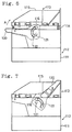
- the mating of the male and female connector housings 111 and 114 will now be described.
- the female connector housings 114 are inserted into the accommodating chambers 117 of the male connector housings 111 from the top thereof respectively.
- the cam projections 116 of each female connector housing 114 are guided by the respective insertion grooves 123 downwardly, engaging the respective cam grooves 122.
- the cam projection 116 is forced downwardly by the cam action between the same and the cam groove 122, whereupon the female connector housing 114 is displaced into the mating engagement with the male connector housing 111 as shown in Fig. 7.
- each operating lever 120 adjacent to that of the other operating lever 120 restricts the movement of the other operating lever 120 in such a direction that the bearing holes 121 are disengaged from the respective lever support shafts 119. Consequently, the outer wall employed in the conventional construction need not be provided between the adjacent male connector housings for restricting the movement of each male connector housing, which renders the connector small-sized.
- each coupling member 127 comprises the engaging section 125 and the engaged section 126 engaged with the engaging section 125 so that the male connector housings 111 are coupled together.
- the manner of coupling should not be limited to this.
- Figs. 8 to 10 illustrate a second embodiment of the present invention.
- a multiple lever connector is formed into a twin type including a male connector block 212 comprising two male connector housings 211 coupled to each other so as to be arranged side by side, as shown in Fig. 8.
- the male connector housings 211 are to be mated with female connectors 213 respectively.
- Each female connector 213 includes a female connector housing 214 formed into the shape of a rectangular parallelepiped and accommodating a number of female terminals therein, as well known in the art.
- a cover 215 is integrally provided on the top of the female connector housing 214.
- Two cam projections 216 coaxially projects from central right-hand and left-hand side walls of the female connector housing 214 respectively.
- the male connector block 212 comprises two male connector housings 211 coupled at a coupling portion 217 to each other so that they are arranged side by side, as described above.
- Each male connector housing 211 includes a square female connector accommodating chamber 218 capable of accommodating the female connector housing 214 therein.
- a number of male terminal accommodating cavities 219 are defined beneath the female connector accommodating chamber 218. The distal ends of male terminals (not shown) disposed in the respective cavities 219 are to project in a row into the female connector accommodating chamber 218.
- the coupling portion 217 couples the male connector housings 211 at the back (the lower portion in Fig. 9) and the bottom (the lower portion in Fig. 10) of the male connector block 212.
- the upper and front portions of the coupling portion 217 are open.
- a two-legged operating lever 221 has two bearing holes 222 formed in legs 221a thereof respectively.
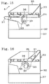
- the lever support shafts 220 are fitted into the bearing holes 222 respectively so that the operating lever 221 is rotatably mounted on the male connector housing 211 so as to straddle the same, as shown in Fig. 10.
- Each leg 221a has an arced cam groove 223 formed about the bearing hole 222 and an insertion groove 224 extending from the right-hand edge of the inner face thereof to the right-hand end of the cam groove 223.
- the cam projections 216 of the female connector housing 214 are inserted through the insertion grooves 224 into the cam grooves 223, thereby engaging them, respectively.
- the male connector block 212 has two outer walls 225 integrally formed on the right-hand and left-hand side walls thereof.
- One of the legs 221a of one operating lever 221 is held between one of the outer wall 225 and the right-hand side wall of one male connector housing 211 while one of the legs 221a of the other operating lever 221 is held between the other outer wall 225 and the left-hand side wall of the other male connector housing 211.
- the width of a space between the outer wall 225 and the side wall of the male connector housing 211 is set so as to be equal to or slightly larger than the thickness of each leg 221a of the operating lever 221.
- the right-hand side wall of the left-hand male connector housing 211 and the left-hand side wall of the right-hand male connector housing 211 are provided with no such outer wall as described above and accordingly, these walls are opposite to each other.
- the width X of a space between the walls are set so that a space larger than the allowance for the engagement between the lever support shaft 220 and the bearing hole 222 is defined between the operating levers 221 when they have been mounted on the respective male connector housings 211.
- a holding groove 212a is formed in a part of the coupling portion 217 of the male connector block 212, the part corresponding to the space between the operating levers 221.
- a restricting plate 226 is detachably forced into the holding groove 212a.
- the thickness of the restricting plate 226 is set so as to be slightly smaller than the space x 0 between the operating levers 221 mounted on the respective male connector housings 211.
- the leg 221a of each operating lever 221 when flexed, comes into contact with the restricting plate 226. Consequently, the amount of flexure of the operating lever 221 is restricted to the value smaller than the allowance y 0 for the engagement between the lever support shaft 220 and the bearing hole 222.
- the lever 221 is taken in hands and the legs 221a are applied to the side walls of the male connector housing 211 so that the lever 221 straddles it.
- the lower ends of the legs 221a are pushed against the respective lever support shafts 220.
- the lever 221 is forced down, the legs 221a are flexed such that they are expanded by the lever support shafts 220 respectively.
- the lever support shafts 220 are fitted into the respective bearing holes 222, whereupon the lever 221 is rotatably mounted on the male connector housing 211.
- the left-hand leg 221a of the operating lever 221 is flexed without restraint.
- the right-hand leg 221a collides with the inner face of the outer wall 225 of the male connector housing 211, it is flexed outwardly, pushing the inner face of the wall.
- the other operating lever 221 is then mounted on the left-hand male connector housing 211 in the same manner as described above. Thereafter, the mounting of the operating levers 221 is completed when the restricting plate 226 is forced into the holding groove 212a formed in the coupling portion 217 of the male connector block 212.
- the right-hand leg 221a of the second operating lever 221 is flexed outwardly when it is mounted on the left-hand male connector housing 211.
- the space x 0 between the operating levers 221 mounted on the respective male connector housings 211 is set to be larger than the allowance y 0 for the engagement between the lever support shaft 220 and the bearing hole 222. Consequently, the required flexure of the operating lever 221 is allowed, so that the lever support shaft 220 is fitted into the bearing hole 222.
- the legs 221a of the lever 221 are flexed and the lever support shafts 220 are drawn out of the respective bearing holes 222 after the restricting plate 226 has been pulled out of the holding groove 212a.
- the restricting plate 226 is forced into the holding groove 212a between the male connector housings 211 to restrict the flexure of the lever 221 after the levers 221 have been mounted on the respective male connector housings 211.
- the above-described construction does not necessitate provision of the outer walls on the left-hand side of one connector housing and the right-hand side of the other connector housing respectively. Two outer walls can be eliminated and the lateral dimension of the male connector block 212 can be reduced accordingly.
- the restricting plate 226 restricting the flexure of each lever 221 is detachable, the lever 221 can be replaced by a new one at need.
- the restricting plate 226 may be undetachably mounted in the holding groove 212a, for example, by use of adhesive. In this case, too, the effect of the present invention can be achieved.
- the restricting plate 226 is forced into the holding groove 212a to be held in position in the foregoing embodiment, it may be inserted into the space between the male connector housings 211 so that the rotative movement of the lever 221 is allowed.
- cam projections 216 are formed on the housing 214 of each female connector 213 in the foregoing embodiment, they may project from the cover 215 of each female connector 213 instead. Furthermore, the male and female terminals may be disposed in the reversed relation to that described above.
- Figs. 11 to 18 illustrate a third embodiment of the invention.
- the multiple lever connector assembly is formed into a twin type including two male connectors 312 having respective operating levers 311 and coupled to each other so that they are arranged side by side, as shown in Fig. 11.
- the male connectors 312 are to be mated with female connectors 313 respectively. Since the male connectors 312 have the same construction, one of them will be described.
- Each female connector 313 includes a female connector housing 314 formed into the shape of a rectangular parallelepiped and accommodating a number of female terminals therein, as well known in the art.
- a cover 315 is integrally provided on the top of the female connector housing 314.
- Two cam projections 316 coaxially projects from central right-hand and left-hand side walls of the female connector housing 314 respectively.
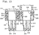
- the male connector 312 includes a male connector housing 317 formed into the shape of a rectangular parallelepiped and a square female connector accommodating chamber 318 capable of accommodating the female connector housing 314 therein.
- a number of male terminal accommodating cavities 319 are defined beneath the female connector accommodating chamber 318. The distal ends of male terminals (not shown) disposed in the respective cavities 319 are to project in a row into the female connector accommodating chamber 318.
- Two lever support shafts 320 coaxially project from the outer faces of the right-hand and left-hand side walls of the female connector accommodating chamber 318 of the male connector housing 317 respectively.
- the length of projection of each lever support shaft 320 is set to be about 1.5 mm.
- a two-legged operating lever 311 has two bearing holes 321 formed in legs 311a thereof respectively as shown in Fig 14.
- the lever support shafts 320 are fitted into the bearing holes 321 respectively so that the operating lever 311 is rotatably mounted on the male connector housing 317 so as to straddle the same.
- Each male connector housing 317 has two outer walls 322 integrally formed on the right-hand and left-hand side walls thereof.
- the legs 311a of the lever 311 are put between the right-hand and left-hand side walls of the male connector housing 317 and the outer walls 322 respectively.
- the width of a space between the outer walls 322 and the side walls of the male connector housings 317 respectively are set so as to be equal to or slightly larger than the thickness of each leg 311a of the operating lever 311.
- Each leg 311a has an arced cam groove 323 formed about the bearing hole 321 and an insertion groove 324 extending from the right-hand edge of the inner face thereof to the right-hand end of the cam groove 323.
- the cam projections 316 of the cover 315 provided on the female connector housing 314 are inserted through the insertion grooves 324 into the cam grooves 323, thereby engaging them, respectively.
- Each leg 311a of the operating lever 311 further has a projection accommodating groove 325 depressed in the inner face thereof and extending from the left-hand edge thereof to the bearing hole 321.
- the groove 325 has such a width that the lever support shaft 320 is allowed to enter the same and a depth set to be about one half of the allowance for engagement between the lever support shaft 320 and the bearing hole 325 or about 1 mm.
- the groove 325 extends so as to be deviated from line A (Fig. 17) drawn between the cam projection 316 and the lever support shaft 320 in the state that the maximum resistance is reached when the lever 311 is rotatively moved for the mating of the male and female connectors 312 and 313, as will be understood in the later description of the operation. More specifically, the groove 325 is formed to extend at an angle of about 60 degrees to line A.
- the mounting of the operating lever 311 on the male connector housing 317 will now be described.
- the operating lever 311 is first disposed to straddle the male connector housing 317 from above.
- the legs 311a of the lever 311 are then inserted into the spaces between the side walls of the male connector housing 317 and the outer walls 322 respectively, and then, the edges of the projection accommodating grooves 325 are applied to the respective lever support shafts 320.
- the lever 311 is forced down in this state, the legs 311a are expanded by the lever support shafts 320 to be pushed against the inner faces of the outer walls 322 respectively.
- the outer walls 322 of the male connector housing 317 are flexed by the respective legs 311a of the operating lever 311 so as to expand outwardly and consequently, the lever support shafts 320 are engaged with the respective bearing holes 321 as in the conventional lever connector.
- the operating lever 311 is provided with the projection accommodating grooves 325 formed to extend from the edges of the legs 311a of the bearing holes 321 respectively. Accordingly, the distal ends of the lever support shafts 320 are located in the projection accommodating grooves 325 until the lever support shafts 320 are fitted into the bearing holes 321, respectively.
- each groove 325 is depressed from the inner surface of the leg 311a, the thickness of the portion of the leg 311a where the groove 325 is formed is reduced as compared with the other portion of the lever 311. Consequently, even though each leg 311a of the operating lever 311 is flexed to expand in the same manner as in the prior art, an amount of flexure of each leg 311a in the embodiment is about two-thirds of that in the conventional lever connector in which the amount of flexure corresponds to the thickness of each leg of the operating lever without the projection accommodating groove 325. Thus, the insertion resistance of the operating lever 311 can be reduced accordingly, which improves the assembling efficiency.
- each leg 311a of the operating lever 311 and each outer wall 322 of the male connector housing 317 can reduce a space defined between the adjacent outer walls 322 of both male connector housings 317 for the purpose of allowing each outer wall to flex. Consequently, the size of the lever connector assembly can be reduced.
- the female connector housing 314 is inserted into the accommodating chamber 318 of the male connector housing 317 from the top thereof.
- the cam projections 316 of each female connector housing 314 are guided downwardly by the respective insertion grooves 324 of the operating lever 311, engaging the respective cam grooves 323.
- the cam projection 316 is forced downwardly by the cam action between the same and the cam groove 323, whereupon the female connector housing 314 is displaced into the mating engagement with the male connector housing 317 as shown in Fig. 16.
- each cam groove 323 pushes the cam projection 316 downwardly.
- the insertion resistance due to the frictional resistance between each pair of male and female terminals acts on the operating lever 311 so that it is pushed upwardly.
- the insertion resistance is not uniform during the rotative movement of the lever 311 but varies with the angle of rotative movement. More specifically, the insertion resistance varies as shown in Fig. 18 and the maximum insertion resistance appears in a first half of the rotative movement of the lever 311. The lever 311 is subjected to the largest force pushing it upwardly when having been rotatively moved to the position where the maximum insertion resistance appears.
- cam projections 316 are provided on the housing 314 of the female connector 313 in the foregoing embodiment, they may project from the cover 315 of the female connector 313, instead. Furthermore, the male and female terminals may be disposed in the reversed relation to that described above.
Landscapes
- Details Of Connecting Devices For Male And Female Coupling (AREA)
Applications Claiming Priority (10)
| Application Number | Priority Date | Filing Date | Title |
|---|---|---|---|
| JP66820/93 | 1993-11-18 | ||
| JP66819/93 | 1993-11-18 | ||
| JP6682093U JP2568738Y2 (ja) | 1993-11-18 | 1993-11-18 | レバー式コネクタ |
| JP6681993U JP2568737Y2 (ja) | 1993-11-18 | 1993-11-18 | レバー式コネクタ |
| JP6681993 | 1993-11-18 | ||
| JP6682093 | 1993-11-18 | ||
| JP1993066836U JP2583277Y2 (ja) | 1993-11-19 | 1993-11-19 | レバー式コネクタ |
| JP6683693 | 1993-11-19 | ||
| JP66836/93 | 1993-11-19 | ||
| EP94118239A EP0654863B1 (de) | 1993-11-18 | 1994-11-18 | Zusammenbau von mehreren Hebelverbindern |
Related Parent Applications (1)
| Application Number | Title | Priority Date | Filing Date |
|---|---|---|---|
| EP94118239A Division EP0654863B1 (de) | 1993-11-18 | 1994-11-18 | Zusammenbau von mehreren Hebelverbindern |
Publications (2)
| Publication Number | Publication Date |
|---|---|
| EP0886345A2 true EP0886345A2 (de) | 1998-12-23 |
| EP0886345A3 EP0886345A3 (de) | 1999-11-17 |
Family
ID=27299258
Family Applications (2)
| Application Number | Title | Priority Date | Filing Date |
|---|---|---|---|
| EP94118239A Expired - Lifetime EP0654863B1 (de) | 1993-11-18 | 1994-11-18 | Zusammenbau von mehreren Hebelverbindern |
| EP98113836A Ceased EP0886345A3 (de) | 1993-11-18 | 1994-11-18 | Zusammenbau von mehreren Hebelverbindern |
Family Applications Before (1)
| Application Number | Title | Priority Date | Filing Date |
|---|---|---|---|
| EP94118239A Expired - Lifetime EP0654863B1 (de) | 1993-11-18 | 1994-11-18 | Zusammenbau von mehreren Hebelverbindern |
Country Status (3)
| Country | Link |
|---|---|
| US (1) | US5586894A (de) |
| EP (2) | EP0654863B1 (de) |
| DE (1) | DE69423294T2 (de) |
Cited By (1)
| Publication number | Priority date | Publication date | Assignee | Title |
|---|---|---|---|---|
| EP1158624A3 (de) * | 2000-05-01 | 2002-04-03 | Sumitomo Wiring Systems, Ltd. | Hebelsteckverbinder |
Families Citing this family (9)
| Publication number | Priority date | Publication date | Assignee | Title |
|---|---|---|---|---|
| JP3472666B2 (ja) * | 1996-07-24 | 2003-12-02 | 矢崎総業株式会社 | コネクタ |
| GB9713593D0 (en) * | 1997-06-28 | 1997-09-03 | Smiths Industries Plc | Connectors |
| JP3585083B2 (ja) * | 1997-12-22 | 2004-11-04 | 矢崎総業株式会社 | コネクタロック機構 |
| JP2003249309A (ja) * | 2002-02-26 | 2003-09-05 | Sumitomo Wiring Syst Ltd | 分割コネクタ |
| US7317619B2 (en) * | 2004-08-02 | 2008-01-08 | International Business Machines Corporation | Apparatus for inserting and ejecting an electronic enclosure within a cabinet |
| JP5009538B2 (ja) * | 2006-02-02 | 2012-08-22 | 矢崎総業株式会社 | レバー式コネクタ |
| DE102006006914B4 (de) * | 2006-02-15 | 2008-07-24 | Phoenix Contact Gmbh & Co. Kg | Vorrichtung zur Befestigung eines Steckverbinders auf einem Tragelement |
| DE102020201330B4 (de) * | 2019-08-23 | 2024-05-29 | Robert Bosch Gesellschaft mit beschränkter Haftung | Steckverbinder-Baugruppe |
| DE102020201331B4 (de) * | 2019-08-23 | 2024-07-04 | Robert Bosch Gesellschaft mit beschränkter Haftung | Steckverbinder-Baugruppe |
Family Cites Families (9)
| Publication number | Priority date | Publication date | Assignee | Title |
|---|---|---|---|---|
| US4241966A (en) * | 1979-04-26 | 1980-12-30 | Thomas & Betts Corporation | Connector with ejector-retainer means |
| US4469393A (en) * | 1981-10-02 | 1984-09-04 | Westinghouse Electric Corp. | Modular connector |
| US4447101A (en) * | 1982-04-12 | 1984-05-08 | Litton Systems, Inc. | Connector with removable ejector latch |
| US4995821A (en) * | 1990-04-17 | 1991-02-26 | Amp Incorporated | Module retention/ejection system |
| US5135410A (en) * | 1990-05-30 | 1992-08-04 | Sumitomo Wiring Systems, Ltd. | Electric connector assembly |
| JP2914593B2 (ja) * | 1991-06-26 | 1999-07-05 | 矢崎総業株式会社 | 操作レバーを利用した低挿入力コネクタ |
| JP2624049B2 (ja) * | 1991-09-13 | 1997-06-25 | 住友電装株式会社 | コネクタ |
| JP2772320B2 (ja) * | 1992-10-07 | 1998-07-02 | 矢崎総業株式会社 | 低挿入力コネクタ |
| JP2583261Y2 (ja) * | 1992-12-24 | 1998-10-22 | 住友電装株式会社 | レバー式コネクタ |
-
1994
- 1994-11-17 US US08/343,898 patent/US5586894A/en not_active Expired - Lifetime
- 1994-11-18 EP EP94118239A patent/EP0654863B1/de not_active Expired - Lifetime
- 1994-11-18 EP EP98113836A patent/EP0886345A3/de not_active Ceased
- 1994-11-18 DE DE69423294T patent/DE69423294T2/de not_active Expired - Fee Related
Cited By (2)
| Publication number | Priority date | Publication date | Assignee | Title |
|---|---|---|---|---|
| EP1158624A3 (de) * | 2000-05-01 | 2002-04-03 | Sumitomo Wiring Systems, Ltd. | Hebelsteckverbinder |
| US6488516B2 (en) | 2000-05-01 | 2002-12-03 | Sumitomo Wiring System, Ltd. | Lever-type connector |
Also Published As
| Publication number | Publication date |
|---|---|
| EP0654863A3 (de) | 1996-06-19 |
| DE69423294T2 (de) | 2000-07-20 |
| DE69423294D1 (de) | 2000-04-13 |
| US5586894A (en) | 1996-12-24 |
| EP0654863A2 (de) | 1995-05-24 |
| EP0654863B1 (de) | 2000-03-08 |
| EP0886345A3 (de) | 1999-11-17 |
Similar Documents
| Publication | Publication Date | Title |
|---|---|---|
| US6644992B2 (en) | Lever-type connector | |
| US6183277B1 (en) | Lever fitting-type connector | |
| US20020064994A1 (en) | Connector | |
| US6716069B2 (en) | Connector with a housing and a retainer held securely on the housing | |
| EP1211752A2 (de) | Elektrischer Steckverbinder der Art mit geringer Steckkraft | |
| US5435738A (en) | Lever-type connector | |
| JP3301329B2 (ja) | コネクタ | |
| EP1418649B1 (de) | Verbinder | |
| US5980283A (en) | Lever-fitting type connector with lever insertion limitation and withdrawal portion | |
| US7114981B1 (en) | Receptacle connector with latch mechanism | |
| EP0886345A2 (de) | Zusammenbau von mehreren Hebelverbindern | |
| JP3683516B2 (ja) | コネクタのロック機構 | |
| EP0646992B1 (de) | Elektrische Steckverbindung mit einem verbesserten Verriegelungshebel | |
| US6048226A (en) | Front holder-incorporating connector | |
| KR100615894B1 (ko) | 커넥터의 하우징 및 이를 이용한 커넥터 | |
| US6860767B2 (en) | Connector having an improved front holder design for retaining terminals | |
| JPH09245869A (ja) | 端子係止具付きコネクタ | |
| CN114628937B (zh) | 连接器 | |
| US6322387B2 (en) | Latching connector assembly | |
| JP3961233B2 (ja) | コネクタの誤結防止構造 | |
| EP1315247A2 (de) | Elektrischer Steckverbinder mit Abdeck- und Ausrichtmitteln | |
| JP3402435B2 (ja) | プリント基板用コネクタ | |
| JP4274570B2 (ja) | コネクタ | |
| US5810619A (en) | Double lock connector with flexible lance on spacer | |
| JPH1079269A (ja) | プリント基板用コネクタ |
Legal Events
| Date | Code | Title | Description |
|---|---|---|---|
| PUAI | Public reference made under article 153(3) epc to a published international application that has entered the european phase |
Free format text: ORIGINAL CODE: 0009012 |
|
| 17P | Request for examination filed |
Effective date: 19980729 |
|
| AC | Divisional application: reference to earlier application |
Ref document number: 654863 Country of ref document: EP |
|
| AK | Designated contracting states |
Kind code of ref document: A2 Designated state(s): DE GB |
|
| PUAL | Search report despatched |
Free format text: ORIGINAL CODE: 0009013 |
|
| AK | Designated contracting states |
Kind code of ref document: A3 Designated state(s): DE GB |
|
| GRAG | Despatch of communication of intention to grant |
Free format text: ORIGINAL CODE: EPIDOS AGRA |
|
| 17Q | First examination report despatched |
Effective date: 20020129 |
|
| STAA | Information on the status of an ep patent application or granted ep patent |
Free format text: STATUS: THE APPLICATION HAS BEEN REFUSED |
|
| 18R | Application refused |
Effective date: 20020725 |