EP0886402A2 - Procédé et dispositif de communication électrique - Google Patents
Procédé et dispositif de communication électrique Download PDFInfo
- Publication number
- EP0886402A2 EP0886402A2 EP98304714A EP98304714A EP0886402A2 EP 0886402 A2 EP0886402 A2 EP 0886402A2 EP 98304714 A EP98304714 A EP 98304714A EP 98304714 A EP98304714 A EP 98304714A EP 0886402 A2 EP0886402 A2 EP 0886402A2
- Authority
- EP
- European Patent Office
- Prior art keywords
- receive
- transmit
- data
- providing
- pairs
- Prior art date
- Legal status (The legal status is an assumption and is not a legal conclusion. Google has not performed a legal analysis and makes no representation as to the accuracy of the status listed.)
- Withdrawn
Links
Images



Classifications
-
- H—ELECTRICITY
- H04—ELECTRIC COMMUNICATION TECHNIQUE
- H04L—TRANSMISSION OF DIGITAL INFORMATION, e.g. TELEGRAPHIC COMMUNICATION
- H04L12/00—Data switching networks
- H04L12/28—Data switching networks characterised by path configuration, e.g. LAN [Local Area Networks] or WAN [Wide Area Networks]
- H04L12/40—Bus networks
- H04L12/40006—Architecture of a communication node
-
- H—ELECTRICITY
- H04—ELECTRIC COMMUNICATION TECHNIQUE
- H04L—TRANSMISSION OF DIGITAL INFORMATION, e.g. TELEGRAPHIC COMMUNICATION
- H04L12/00—Data switching networks
- H04L12/28—Data switching networks characterised by path configuration, e.g. LAN [Local Area Networks] or WAN [Wide Area Networks]
- H04L12/40—Bus networks
- H04L12/407—Bus networks with decentralised control
- H04L12/413—Bus networks with decentralised control with random access, e.g. carrier-sense multiple-access with collision detection [CSMA-CD]
Definitions
- the invention relates to electronic communications networks. More particularly, the invention relates to a high speed physical layer for CSMA/CD systems.
- 100BASE-TX technology offers full duplex operation at 125 MHz, yet it only requires two pair of cables when it is used on category 5 UTP or shielded twisted pair (STP). Further, 100BASE-TX is widely supported by industry. Unfortunately, this technology provides only marginal signal quality on poor to moderate CAT5 data grade unshielded twisted pair cable (UTP). See the ISO/IEC1801 Wiring Specification. 100BASE-TX is very difficult to implement because of its high bandwidth requirements. Thus, although this technology may be implemented with two pair of cables, in fact it requires all four pair of an unshielded twisted pair cable to ease noise sensitivities. Further, interoperability is difficult to achieve because of the small signal margin available, e.g.
- 100BASE-T4 technology supports CAT 3, 4, and 5 UTP cable.
- this technology only operates at half duplex, which limits its application for switched environments.
- there is no significant industry support for this technology because, for example, the complex waveshaping required to implement this technology has made interoperability difficult to achieve.
- performance of this technology is only marginal on CAT3 wire.
- 100BASE-T2 supports CAT 3, 4, and 5 UTP cables. Further, this technology provides full duplex operation. However, complex signalling requirements of this technology mandates the use of a digital signal processor (DSP). At this time, there is no known industry support for this technology. Finally, it should be noted that this technology is implemented with a continuous carrier that requires high power during ambient operation. This makes 100BASE-T2 technology unattractive for low power or portable applications, such as for use with laptop computers.
- DSP digital signal processor
- None of the prior art techniques provides an electronic communications network technology that offers full duplex operation and robust performance on marginal CAT5 wiring, while taking advantage of industry standard 100BASE-TX functionality.
- No known technology is complementary to 100BASE-TX, as well as compatible with such 100BASE-T features as auto-negotiation.
- the present invention seeks to provide an improved electronic communication network.
- an electronic communication apparatus for providing full duplex exchange at 100 million bits per second via an electronic communications network, comprising: a receive port (31) terminating a receive path and adapted to provide connections to at least two pairs of receive cables; a transmit port (11) terminating a transmit path and adapted to provide connections to at least two pairs of transmit cables; and a receive carrier sense circuit, coupled to said receive port, for detecting carrier amplitude that is indicative of data transmission to provide a carrierless IDLE that requires very low power during ambient operation.
- Preferred embodiments are operable to transmit and receive on two separate pairs of cables (10), thereby reducing the bandwidth per cable pair, reducing attenuation, and allowing an increase in the minimum transmit amplitude, wherein a carrier is not sent during idle, but only during actual transmit; operable to perform transmit carrier detection using amplitude detection techniques found in either the 1 OBASE-T or 1 OOBASE-T4 protocols; operable to use a 2.5 volts peak amplitude during data transmission; operable to send link pulses on both transmit pairs to verify that a full duplex data exchange using said apparatus is supported by said network.
- said receive and transmit cables cumulatively comprise four pairs (10) of data grade unshielded twisted pair cable.
- a media independent interface as defined by the IEEE 802.3u specification.
- said transmit path comprises a multiplexer (12), wherein transmit data received at said transmit data port are multiplexed by said multiplexer in nibble wide groups to allow transmission on said two pairs of transmit cables, and wherein a first nibble goes onto a 1,2 pair p1p2 and a second nibble goes onto a 4,5 pair p4p5; a scrambler (14) to reduce emissions and Near End Crosstalk (NEXT), and to improve transition distribution, wherein a different stream cypher is used for pair 1 and pair 2 of said transmit cables to provide relative dispersion in NEXT content, and wherein said stream cypher is synchronized at a remote receiver with the occurrence of a start of frame delimiter; a 4B to 5B coding circuit (16), as defined by the IEEE 802.3u specification, wherein currently defined J,K and T,R code groups are used to indicate start_delimiter and end_delimiters, respectively; a regulated mark inversion (RMI) encoder (18)
- said receive path comprises one or more of a phase lock loop (PLL), wherein start_delimiters are used to align data being received; a receive adaptive equalization circuit (Fig. 6) for compensating for signal losses encountered in said network; a receive regulated mark inversion decoder circuit (24) for receiving and decoding incoming data; a receive decoder circuit (26) for receiving and decoding an incoming data stream by looking for the occurrence of a preamble, and then aligning a decoder on a start delimiter; a receive descrambler circuit (28) for receiving scrambled data and deciphering said data according to the position of a cypher by using an initialization seed, wherein said descrambler circuit is operable to determine that said preamble and a start of frame delimiter have arrived, thereby placing said apparatus into an initialization state; and a receive deMUX circuit (30) for receiving incoming data and de-multiplex said data from two receive channels, wherein said receive deMUX circuit follows an
- the preferred embodiments provide an electronic communications network technology, which is referred to herein as 100BASE-TD.
- This technology offers full duplex operation and robust performance on marginal CAT5 wiring. It highly leverages 100BASE-TX functional blocks and is very complementary to 100BASE-TX, for example with regard to such 100BASE-TX features as auto-negotiation, 4B to 5B coding, and scrambling.
- Preferred embodiments provide a carrierless IDLE that requires very low power during ambient operation.
- preferred embodiments allow a reduction in the bandwidth per cable pair. This both reduces attenuation and allows an increase in the minimum transmit amplitude. In this way, a carrier need not be sent during idle, but only during actual transmit.
- the reduced bandwidth and higher transmit voltage allows transmit carrier detection using standard amplitude detection techniques, such as those found in 10BASE-T and 100BASE-T4.
- the preferred embodiment of the invention provides a protocol having a slower baud rate than that of 100BASE-TX, e.g. 62.5 MHz as opposed to 125 MHz for 100BASE-TX. Additionally, the invention operates with a higher transmission voltage than that of 1 OOBASE-TX, e.g. 2.5 volts peak amplitude during transmit as opposed to 1 volt peak amplitude during transmit for 100BASE-TX.
- 100BASE-TX also known as Fast Ethernet
- Fast Ethernet also known as Fast Ethernet
- Its continuous transmission technique requires as much as 200mA during quiescent states, which makes it difficult to meet power savings objectives for Green Frame applications, i.e. low power or energy conserving applications.
- Preferred embodiments provide an electronic communications network technology, which is referred to herein as 100BASE-TD.
- This technology offers full duplex operation and robust performance on marginal CATS wiring. It highly leverages 100BASE-TX functional blocks and is very complementary to 100BASE-TX, for example with regard to such 100BASE-TX features as auto-negotiation, 4B5B coding and scrambling. Further, preferred embodiments provide a carrierless IDLE that requires very low power during ambient operation.
- preferred embodiments allow a reduction in the bandwidth per cable pair. This both reduces attenuation and allows an increase in the minimum transmit amplitude. In this way, a carrier need not be sent during idle, but only during actual transmit.
- the reduced bandwidth and higher transmit voltage allows transmit carrier detection using standard amplitude detection techniques, such as those found in 100BASE-T and 100BASE-TX.
- the preferred embodiment of the invention provides a protocol having a slower baud rate than that of 100BASE-TX, e.g. 62.5 MHz as opposed to 125 MHz for 100BASE-TX. Additionally, the invention operates with a higher transmission voltage than that of 100BASE-TX, e.g. 2.5 volts peak amplitude during transmit as opposed to 1 volt peak amplitude during transmit for 100BASE-TX.
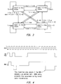
- 100BASE-TD complements 100BASE-TX, by providing a robust physical layer to be used when all four pairs of a CATS UTP cable are available. With the availability of auto-negotiation, it relatively straightforward for a pair of devices to indicate that they support 100BASE-TD. By sending link pulses on both transmit pairs, it is possible to verify that the wire supports the 100BASE-TD technology as well. Auto negotiation uses a repetitive sequence of pulses on the cable to indicate capability of each link partner. In 100BASE-T, there are 16 clock pulses and up to 16 data pulses used to convey information between nodes on the link. While this normally occurs only on one transmit pair and one receive pair, it may also be incorporated into multiple pairs to ensure that the wiring supports multi-pair technology, e.g.
- 100BSE-TD (see Fig. 1).
- the DATA pulses contain information such as technology ability, speed, duplex mode, and allow the two ends of the link to find the highest common denominator.
- 100BASE-TD is thought to be a superior 100Mbps technology because it offers higher reliability and full-duplex operation at a lower average power.
- Fig. 2 is a block schematic diagram of a preferred high speed physical layer for CSMA/CD systems.
- the preferred embodiment of the invention requires four pair of CATS UTP cable. As can be seen on Fig. 2, four pairs of cables 10 are required to provide a network connection using the 100BASE-TD protocol disclosed herein.
- the preferred embodiment of the invention includes at least one transmit port 11 that couples a user system to a network to allow transmission of data thereto, and at least one receive port 31 that couples the user system to the network to allow reception of data thereby.
- 100BASE-TD uses the exact same MII interface as defined by the IEEE 802.3u specification. See Table A below.
- PHY RX_CLK Nibble wide data stream coming from PHY RX_DV PHY RX_CLK Indicates that receive data is valid. This signal is asserted prior to SFD and deasserted prior to EFD RX_ER PHY RX_CLK Indicates a receive error has occurred. This might be due to MLT-3 code violations or 5B4B decode errors CRS PHY N/A This signal is asserted whenever transmit or receive is in progress.
- COL PHY N/A This signal is asserted whenever a collision is detected. In 10Mbps mode, this signal will operate like SQE after a packet has been transmitted.
- RX_CLK PHY The receive data clock which is continuous. If no data is present this clock will be synchronized to the transmit clock and when data is detected, will switch over by holding a pulse high or low for an extended time. This can only occur when RX_DV is false. This signal is nominally 1/4 the data rate.
- TX_EN STA TX_CLK Indicates that transmit data is valid on the rising edge of TX_CLK.
- TX_ER STA TX_CLK Indicates a transmit error has occurred. This signal tells the PHY to begin transmitting HALT symbols to indicate an error exists,m rather than the actual data being transferred.
- TX_CLK PHY N/A The transmit data clock is generated by the PHY as a source for the STA to generate data/control signals. This clock is nominally 1/4 the data rate.
- MDIO STA/PHY MDC Bidirectional signal to transmit control/address/ data between the STA and PHY. Valid on rising edge of MDC.
- the preferred embodiment of the invention includes a multiplexer MUX 12. Transmit data received at a transmit data port 11 are multiplexed by the MUX 12 in nibble wide groups to allow transmission on two pairs. The first nibble goes onto the 1,2 pair p1p2 and the second nibble goes onto the 4,5 pair p4p5. This adds a 4BT clock cycle (40nS each) latency to the system.
- a scrambler 14 is used to reduce emissions and Near End Crosstalk (NEXT), and to improve transition distribution.
- a Stream Cypher (which is a type of data scrambler) is used because of its simplicity and the fact that it does not propagate errors.
- the Stream Cypher seeds for pair 1 and pair 2 are different to provide relative dispersion in NEXT content.
- SFD Start of Frame Delimiter
- the Stream Cypher may be synchronized at the receiver with the occurrence of Start of Frame Delimiter (SFD), i.e . an indication in the 802.3 frame that a packet is beginning. Because the subsequent RMI coder (discuss below) does not create a baseline wander phenomena, the scrambler may be aligned in this way.
- SFD Start of Frame Delimiter
- 100BASE-TD uses the exact same 4B to 5B coding circuit 16 as defined by the IEEE 802.3u specification. This allows leverage of the circuit in a 10/100TX/100TD transceiver.
- the currently defined J,K and T,R code group may be used to indicate start_delimiter and end_delimiters respectively.
- the preferred embodiment of the invention includes a regulated mark inversion (RMI) encoder 18 (see Fig. 3).
- RMI is an encoding technique that tracks the Running Digital Sum (RDS) of the transmitted data and ensures that a DC balance is maintained. This code generates a +1 or a -1 if the binary data presented to it is a one. It generates a 0 if the data presented to it is a zero. It alternates between +1s and -1s at each transition to 0. If the RDS exceeds a limit (e.g. 10 baud) it jumps from the +1 to the -1, or vice-versa.
- the data transition When combined with the 4B to 5B coding, the data transition normally from +1 to 0, 0 to -1,0 to +1, and -1 to 0.
- the use of RMI coding maintains the DC content of the transmitted signal at 0 and thus prevents baseline wander. This simplifies receiver design for a system that incorporate the 100BASE-TD protocol.
- the preferred embodiment of the invention includes a waveshaping circuit 20.
- RMI is transmitted at 62.5 Megabaud.
- the only requirement for waveshaping is to keep the harmonic components down below that of an MLT-125 spectral mask, i.e. the power spectral density curve (energy vs. frequency). This can be done with a relatively simple transmit waveshaper, as is well known in the art.
- the receive portion of the system is also shown in Fig. 2.
- the receive carrier sense circuit, receive phase lock loop (PLL) circuit, receive adaptive equalization circuit, and automatic gain control circuit is each discussed below and are indicated collectively in Fig. 2 by the numeric designation 22.
- a conventional squelch may be used.
- the amplitude of the minimum signal level received is greater than 600mV.
- a squelch level of 350mV is used in the presently preferred embodiment of the invention.
- 100BASE-TD uses a carrierless IDLE
- the PLL must be able to acquire phase lock within 46 baud times after carrier has become present.
- a single PLL may be used for both receive channels, where separate phase detectors are used to center the sampler on the received eye. Whole bits overlapped in time create an eye diagram (see Fig. 5). Because of cable propagation delay differences, skew between pairs may be as much as 50ns. Therefore, a good design should account for up to 100ns skew.
- the start_delimiters may be used on the receiver to align data being received. Skew compensation may take up to another 8BT of delay.
- Adaptive equalization is a technique that is used in receivers to compensate for the signal losses that are encountered in a transmission medium.
- the primary sources of signal loss are the following:
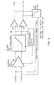
- Adaptive Equalizer Control may be performed digitally by evaluating the amplitude of small and large pulses then modifying the AGC 60 and VGHFB 62 control signals to equalize the relative amplitudes (see Fig. 6.)
- the AGC is used to set up an absolute maximum level (typically based upon large pulse amplitudes as they are minimally affected by UTP cable attenuation) and then the VGHFB circuit parameters may be modified until the long and short pulse amplitudes are matched.
- the key benefit of a digital implementation is that it may be operated at a very low bandwidth by increasing the number of bits used to count the period between updates.
- equalizer adaptation algorithm is best implemented with a digital control circuit By doing so, equalizer settings may be maintained during periods of time when no energy is present. It is possible to use one channel to perform adaptation or to use both receive channels in a way that arrives at a best fit adaptation that compensates for the average channel loss of the two pairs.
- the receive RMI decoder circuit 24 (Fig. 2) receives and decodes the incoming RMI signal. It has the ability to detect coding errors, which may be useful for improving Undetected Bit Error Rates (UBER) beyond that provided by the 5B to 4B Decoder.
- UBER Undetected Bit Error Rates
- the receive 5B to 4B decoder circuit 26 receives and decodes the incoming data stream. It looks for the occurrence of preamble, and then aligns its 5B decoder on the Start-Delimiter. In some embodiments of the invention a filler byte of preamble may be required to ensure proper alignment of 5B symbols with 4B data nibbles at the MII.
- the receive descrambler circuit 28 receives the scrambled 4B data and deciphers it according to the position of the cypher by using its initialization seed.
- the descrambler circuit determines that the preamble and start of Frame Delimiter (SFD) have arrived, which places it into its initialization state.
- SFD Frame Delimiter
- the receive deMUX circuit 30 (Fig. 2) receives the incoming 4B data and demultiplexes it from the two receive channels for delivery to receiver port 31. It follows a simple algorithm which starts with the 3,6 pair then switches to the 7,8 pair, and then repeats (see Fig. 7.)
- Waveshaping must be simple, yet must keep energy levels above 60MHz down below a reasonable level. Waveshaping must be performed to allow common magnetics, e.g. isolation transformers, for 10/100TX/100TD.
- Equalizer Digital Feedack mechanism must hold during silence. This type of circuit has been implemented on 100T4 and 100VG applications. It should be carefully designed to adapt during a few packets worth of time.
- Zero Phase PLL acquisition is designed to implement proper lock on the data cells prior to the detection of Start Delimiter. If bit errors are to occur during the preamble they must not be passed to the MII. A criteria for losing bits on the beginning of carrier must be defined. A digital oversampling technique is preferred (see Fig. 8) because oversampling allows rapid digital acquisition of transition positions.
- RMI Disparity Level is defined such that it ensures DC balance without ever making a +1-1 or -1+1 transition during normal operation.
Landscapes
- Engineering & Computer Science (AREA)
- Computer Networks & Wireless Communication (AREA)
- Signal Processing (AREA)
- Dc Digital Transmission (AREA)
- Small-Scale Networks (AREA)
- Detection And Prevention Of Errors In Transmission (AREA)
- Communication Control (AREA)
- Synchronisation In Digital Transmission Systems (AREA)
- Bidirectional Digital Transmission (AREA)
- Cable Transmission Systems, Equalization Of Radio And Reduction Of Echo (AREA)
Applications Claiming Priority (2)
| Application Number | Priority Date | Filing Date | Title |
|---|---|---|---|
| US87669697A | 1997-06-16 | 1997-06-16 | |
| US876696 | 1997-06-16 |
Publications (2)
| Publication Number | Publication Date |
|---|---|
| EP0886402A2 true EP0886402A2 (fr) | 1998-12-23 |
| EP0886402A3 EP0886402A3 (fr) | 1999-07-21 |
Family
ID=25368384
Family Applications (1)
| Application Number | Title | Priority Date | Filing Date |
|---|---|---|---|
| EP98304714A Withdrawn EP0886402A3 (fr) | 1997-06-16 | 1998-06-15 | Procédé et dispositif de communication électrique |
Country Status (3)
| Country | Link |
|---|---|
| US (1) | US7116678B2 (fr) |
| EP (1) | EP0886402A3 (fr) |
| JP (1) | JPH11234316A (fr) |
Families Citing this family (5)
| Publication number | Priority date | Publication date | Assignee | Title |
|---|---|---|---|---|
| KR20020096799A (ko) * | 2001-06-15 | 2002-12-31 | (주)오버넷 | 시그널링 신호체계를 이용한 비동기 엠아이아이 데이터전송 시스템 |
| US20080280652A1 (en) * | 2007-05-08 | 2008-11-13 | Firefly Mobile, Inc. | Reconfigurable keypad method in handset device operable with plural subsystems |
| US8406337B2 (en) * | 2007-07-31 | 2013-03-26 | Agilent Technologies, Inc. | Method and apparatus for sending DC-balanced signals over a transmission line |
| US9064953B2 (en) * | 2013-06-12 | 2015-06-23 | Infineon Technologies Austria Ag | Semiconductor device including a drift zone and a drift control zone |
| US9318483B2 (en) | 2013-12-23 | 2016-04-19 | Infineon Technologies Austria Ag | Reverse blocking transistor device |
Family Cites Families (11)
| Publication number | Priority date | Publication date | Assignee | Title |
|---|---|---|---|---|
| US5280500A (en) * | 1991-10-10 | 1994-01-18 | Crescendo Communications, Inc. | Method and apparatus for multilevel encoding for a local area network |
| US5439571A (en) * | 1991-11-19 | 1995-08-08 | Bioseparations, Inc. | Apparatus and method for enhanced resolution continuous flow zone electrophoresis |
| US5216714A (en) * | 1991-12-13 | 1993-06-01 | 3Com Corporation | Method and apparatus for controlling the spectral content of a data stream |
| US5438571A (en) * | 1992-11-06 | 1995-08-01 | Hewlett-Packard Company | High speed data transfer over twisted pair cabling |
| GB9314480D0 (en) * | 1993-07-09 | 1993-08-25 | Hewlett Packard Co | Encoding data |
| US5544323A (en) * | 1993-09-23 | 1996-08-06 | Standard Microsystems Corp. | High bit rate ethernet connection |
| US5784573A (en) * | 1994-11-04 | 1998-07-21 | Texas Instruments Incorporated | Multi-protocol local area network controller |
| DE69527935T2 (de) * | 1995-03-06 | 2003-04-30 | Hewlett-Packard Co. (N.D.Ges.D.Staates Delaware), Palo Alto | Gleichtaktfreier ternärer Kode |
| EP0824817B1 (fr) * | 1996-03-11 | 2005-08-03 | Hewlett-Packard Company, A Delaware Corporation | Appareil et procede de transmission de blocs de mots de donnees avec des mots de controle |
| GB9614561D0 (en) * | 1996-07-11 | 1996-09-04 | 4Links Ltd | Communication system with improved code |
| EP0863640A3 (fr) * | 1997-03-04 | 2005-09-21 | Texas Instruments Incorporated | Dispositif d'interface perfectionné pour la couche physique |
-
1998
- 1998-06-12 JP JP10181492A patent/JPH11234316A/ja active Pending
- 1998-06-15 EP EP98304714A patent/EP0886402A3/fr not_active Withdrawn
-
2004
- 2004-04-30 US US10/837,264 patent/US7116678B2/en not_active Expired - Lifetime
Also Published As
| Publication number | Publication date |
|---|---|
| US20040218621A1 (en) | 2004-11-04 |
| EP0886402A3 (fr) | 1999-07-21 |
| JPH11234316A (ja) | 1999-08-27 |
| US7116678B2 (en) | 2006-10-03 |
Similar Documents
| Publication | Publication Date | Title |
|---|---|---|
| US5673254A (en) | Enhancements to 802.3 media access control and associated signaling schemes for ethernet switching | |
| EP0714191B1 (fr) | Transfert de données à grande vitesse par câbles à paires torsadées | |
| US5438571A (en) | High speed data transfer over twisted pair cabling | |
| US7415013B1 (en) | Reduced pin gigabit media independent interface | |
| US8422512B2 (en) | Method and system for an extended range ethernet line code | |
| US7920597B2 (en) | Method and system for low power idle signal transmission in ethernet networks | |
| US7227869B2 (en) | Serial media independent interface | |
| US7602806B2 (en) | Signaling and coding methods and apparatus for long-range 10 and 100 MBPS ethernet transmission | |
| US6169729B1 (en) | 200 Mbps PHY/MAC apparatus and method | |
| US6088827A (en) | 1000BASE-T packetized trellis coder | |
| US6618392B1 (en) | Network transceiver using signal detect input to control modes of operation | |
| US6944587B2 (en) | Ethernet adapting apparatus | |
| US20060064513A1 (en) | System and method for providing compatibility between different transceivers in a multi-pair communication system | |
| US7570591B2 (en) | Method and apparatus for negotiating link speed and configuration | |
| US5881074A (en) | 1000base-t packetized trellis coder | |
| US7031333B1 (en) | Reduced pin count media independent interface | |
| US7116678B2 (en) | High speed physical layer for CSMA/CD systems | |
| US6842481B1 (en) | Apparatus and method for secure media independent interface communications by corrupting transmit data on selected repeater port | |
| Crayford | " Fast Ethernet" alternatives for client-server computing | |
| Buchanan | Ethernet | |
| Jain | Recent Advances in 100 Mbps LAN Technologies |
Legal Events
| Date | Code | Title | Description |
|---|---|---|---|
| PUAI | Public reference made under article 153(3) epc to a published international application that has entered the european phase |
Free format text: ORIGINAL CODE: 0009012 |
|
| AK | Designated contracting states |
Kind code of ref document: A2 Designated state(s): AT BE CH CY DE DK ES FI FR GB GR IE IT LI LU MC NL PT SE |
|
| AX | Request for extension of the european patent |
Free format text: AL;LT;LV;MK;RO;SI |
|
| PUAL | Search report despatched |
Free format text: ORIGINAL CODE: 0009013 |
|
| RIC1 | Information provided on ipc code assigned before grant |
Free format text: 6H 04L 12/413 A, 6H 04L 12/44 B |
|
| AK | Designated contracting states |
Kind code of ref document: A3 Designated state(s): AT BE CH CY DE DK ES FI FR GB GR IE IT LI LU MC NL PT SE |
|
| AX | Request for extension of the european patent |
Free format text: AL;LT;LV;MK;RO;SI |
|
| AKX | Designation fees paid | ||
| REG | Reference to a national code |
Ref country code: DE Ref legal event code: 8566 |
|
| STAA | Information on the status of an ep patent application or granted ep patent |
Free format text: STATUS: THE APPLICATION IS DEEMED TO BE WITHDRAWN |
|
| 18D | Application deemed to be withdrawn |
Effective date: 20000122 |