EP0886882B1 - Lampe luminescente a gaz, notamment pour phare de vehicule - Google Patents
Lampe luminescente a gaz, notamment pour phare de vehicule Download PDFInfo
- Publication number
- EP0886882B1 EP0886882B1 EP97916330A EP97916330A EP0886882B1 EP 0886882 B1 EP0886882 B1 EP 0886882B1 EP 97916330 A EP97916330 A EP 97916330A EP 97916330 A EP97916330 A EP 97916330A EP 0886882 B1 EP0886882 B1 EP 0886882B1
- Authority
- EP
- European Patent Office
- Prior art keywords
- gas discharge
- discharge lamp
- electrode
- cap
- lamp according
- Prior art date
- Legal status (The legal status is an assumption and is not a legal conclusion. Google has not performed a legal analysis and makes no representation as to the accuracy of the status listed.)
- Expired - Lifetime
Links
Images
Classifications
-
- H—ELECTRICITY
- H05—ELECTRIC TECHNIQUES NOT OTHERWISE PROVIDED FOR
- H05B—ELECTRIC HEATING; ELECTRIC LIGHT SOURCES NOT OTHERWISE PROVIDED FOR; CIRCUIT ARRANGEMENTS FOR ELECTRIC LIGHT SOURCES, IN GENERAL
- H05B41/00—Circuit arrangements or apparatus for igniting or operating discharge lamps
- H05B41/02—Details
- H05B41/04—Starting switches
- H05B41/042—Starting switches using semiconductor devices
-
- F—MECHANICAL ENGINEERING; LIGHTING; HEATING; WEAPONS; BLASTING
- F21—LIGHTING
- F21S—NON-PORTABLE LIGHTING DEVICES; SYSTEMS THEREOF; VEHICLE LIGHTING DEVICES SPECIALLY ADAPTED FOR VEHICLE EXTERIORS
- F21S41/00—Illuminating devices specially adapted for vehicle exteriors, e.g. headlamps
- F21S41/10—Illuminating devices specially adapted for vehicle exteriors, e.g. headlamps characterised by the light source
- F21S41/14—Illuminating devices specially adapted for vehicle exteriors, e.g. headlamps characterised by the light source characterised by the type of light source
- F21S41/17—Discharge light sources
-
- F—MECHANICAL ENGINEERING; LIGHTING; HEATING; WEAPONS; BLASTING
- F21—LIGHTING
- F21S—NON-PORTABLE LIGHTING DEVICES; SYSTEMS THEREOF; VEHICLE LIGHTING DEVICES SPECIALLY ADAPTED FOR VEHICLE EXTERIORS
- F21S41/00—Illuminating devices specially adapted for vehicle exteriors, e.g. headlamps
- F21S41/10—Illuminating devices specially adapted for vehicle exteriors, e.g. headlamps characterised by the light source
- F21S41/19—Attachment of light sources or lamp holders
- F21S41/192—Details of lamp holders, terminals or connectors
-
- H—ELECTRICITY
- H01—ELECTRIC ELEMENTS
- H01J—ELECTRIC DISCHARGE TUBES OR DISCHARGE LAMPS
- H01J61/00—Gas-discharge or vapour-discharge lamps
- H01J61/02—Details
- H01J61/56—One or more circuit elements structurally associated with the lamp
-
- H—ELECTRICITY
- H01—ELECTRIC ELEMENTS
- H01J—ELECTRIC DISCHARGE TUBES OR DISCHARGE LAMPS
- H01J61/00—Gas-discharge or vapour-discharge lamps
- H01J61/84—Lamps with discharge constricted by high pressure
Definitions
- the invention relates to a gas discharge lamp, in particular for motor vehicle headlights, by type of the main claim.
- Gas discharge lamp or high pressure discharge lamp is the ballast required for supply the lamp with the necessary ignition and burning voltage in a molded housing arranged on the rear part of the Reflector of the motor vehicle headlight unit arranged is.
- This housing increases the overall depth the motor vehicle headlight unit, the high-voltage carrying Lines from the molded housing to Burner vessel of the lamp must be guided. This brings Isolation problems and line losses.
- a low-pressure gas discharge lamp is already known from EP-A-0 150 799 the genus mentioned at the beginning, in which the ballast is arranged on the lamp base.
- An inductive ignition component contained in the ballast, in particular an ignition pulse transmitter, according to one advantageous embodiment of the invention a closed Core, preferably a toroidal core, whereby with a low number of turns can achieve a high inductance leaves. This leads to a slow ignition pulse, and the ignition voltage can be kept low. Farther the low number of turns enables a compact and small volume construction.
- the closed core preferably encompasses one of the both end areas provided with an electrode bushing of the burner vessel, which also leads to a reduction contributes to the size.
- Lamp base By at least partially encapsulating or potting the components required for the ballast with an end region of the burner vessel with plastic material can be a simple and inexpensive way Lamp base are formed, in addition to its function as Lamp base still holds the components together and to that Burner vessel binds.
- This lamp base also serves at the same time as an insulating body, expediently the electrical connections of the lamp base as well are encapsulated or encapsulated, so that practically the entire lamp base is formed in one operation.
- the im Lamp base extending area of the outer lead expediently encapsulated or encapsulated at the same time become.
- auxiliary electrode preferably in the vicinity of the first main electrode near the base is arranged.
- the Polarity of the first main electrode near the base is negative against the polarity of the others, with the auxiliary electrode connected second main electrode. This will ensured that after the initial spark from the first main electrode near the base to the auxiliary electrode jumps through the glass wall of the burner vessel through, the subsequent spark towards the second main electrode follow the first main electrode without changing polarity can.
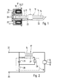
- the gas discharge lamp shown in Fig. 1 consists of essentially from a burner vessel 10 which in one Lamp base 11 is embedded. That made of glass or one other transparent, temperature-resistant material existing burner vessel 10 has a central combustion chamber 12 with flattened spherical shape or ellipsoidal shape, the two on the opposite sides are tubular Has extensions 13, 14. The end areas of this tubular Extensions 13, 14 are gas-tight feedthroughs designed for two main electrodes 15, 16, which is slightly from both sides in the combustion chamber 12 stretch in. Between these main electrodes 15, 16 arcs are formed during operation.
- the lamp base 11 is as a molded body or injection molded body trained and consists of insulating plastic material. It contains an ignition pulse transmitter 17 which from a toroidal core 18 and a winding arrangement 24, 27 for the Toroidal core 18 is made.
- the ring core 18 concentrically surrounds the first tubular extension 13, which is in the lamp base 11 stretched in. Furthermore are in the lamp base 11 contain electronic components 19, which only are shown schematically and together with the Ignition pulse transformer 17 form a ballast that the Lamp with the required ignition and burning voltage provided.
- the lamp base 11 also has two ring-shaped ones electrical connections 20, 21, of which the inner with the first main electrode 15 and of which the outer with the ignition pulse transmitter 17 is connected.
- a second Connection of the ignition pulse transmitter 17 is with a outer line 22 connected from the lamp base 11 extends essentially parallel to the burner vessel 10 and at its free end with the second main electrode 16 is electrically connected.
- This outer line 22 is designed as a wire or rod.
- the outer line 22 In the connection area between the first tubular extension 13 and the combustion chamber 12 is the outer line 22 to this first extension 13 out there and forms an outer auxiliary electrode 23, which is thus electrically connected to the second main electrode 16 is connected.
- This auxiliary electrode 23 can also as a conductive strip, e.g. as a conductive paint strip made of conductive silver or the like.
- the ignition pulse transmitter 17, the burner vessel 10, the electronic components 19, the electrical connections 20, 21 and the outer line 22 are together with Injection molded plastic material to form the lamp base 11 or shed.
- the lamp base 11 can the lamp in a socket for example one Motor vehicle headlights are inserted.
- Fig. 2 is a possible circuit for a ballast shown.
- the two electrical connections 20, 21 are connected in series via a first winding 24 of the ignition pulse transmitter 17 with the two main electrodes 15, 16 of the burner vessel 10 connected to one another.
- the two electrical connections 20, 21 via the series connection of a capacitor 25 with a Resistor 26 connected. Is parallel to the capacitor 25 the series connection of a second winding 27 of the ignition pulse transmitter 17 switched with a spark gap 28.
- the circuit shown in Fig. 2 merely represents one of many known options for such Ballast.
- Other circuits for ballasts of gas discharge lamps are, for example, in "Lamps and Lighting", 2nd edition, S. T. Henderson and A. M. Marsden, p. 328 ff.
- the lamp base 11 also as a prefabricated housing for Recording of the components, such as ignition pulse transmitters 17, Burner vessel 10, electrical components 19, electrical Connections 20, 21 and outer line 22 may be formed.
- the auxiliary electrode 23 also omitted, have a different shape or as Electrode supplied separately with an ignition voltage be trained.
Landscapes
- Engineering & Computer Science (AREA)
- General Engineering & Computer Science (AREA)
- Non-Portable Lighting Devices Or Systems Thereof (AREA)
- Common Detailed Techniques For Electron Tubes Or Discharge Tubes (AREA)
Abstract
Claims (10)
- Lampe luminescente à gaz, en particulier pour phares de véhicules à moteur, comprenant une ampoule en verre ou en une matière analogue, présentant au moins deux électrodes pourvues d'un socle de lampe présentant les raccords électriques et un régulateur de la puissance de wattage électronique, qui fournit à la lampe la tension d'allumage et de fonctionnement nécessaire, disposé dans le socle de lampe,
caractérisée en ce quele socle de lampe (11) pourvu du régulateur de la puissance de wattage est constitué de façon à pouvoir être enfiché dans un logement du socle,l'ampoule (10) se compose essentiellement d'une chambre de combustion (12) et de deux prolongements (13, 14) en forme de tubes, s'étendant à partir de cette chambre de combustion(12) en sens opposés, et contenant chacun une électrode principale (15, 16), les zones terminales opposées des prolongements (13, 14) contenant les passages pour les électrodes, etle branchement d'électrodes, disposé dans la zone terminale (14) de l'ampoule (10) éloignée du socle de la lampe (11), retourne par une ligne extérieure (20) au socle de la lampe (11) et est branché à cet endroit à un raccordement électrique correspondant. - Lampe luminescente à gaz selon la revendication 1,
caractérisée en ce que
un composant d'allumage (17) à induction, contenu dans le régulateur de la puissance de wattage, en particulier un transformateur d'impulsions d'allumage, possède un noyau fermé (18). - Lampe luminescente à gaz selon la revendication 2,
caractérisée en ce que
le noyau fermé (18) est un noyau annulaire. - Lampe luminescente à gaz selon la revendication 2 ou 3,
caractérisée en ce que
le noyau fermé (18) entoure l'une des deux zones terminales (13) de l'ampoule (10) qui est pourvue d'un branchement d'électrodes. - Lampe luminescente à gaz selon l'une des revendications précédentes,
caractérisée en ce que
les composants (17, 18), nécessaires au régulateur de la puissance de wattage, sont enrobés par injection ou coulés en même temps qu'une zone terminale (13) de l'ampoule (10) au moins en partie avec la matière plastique qui constitue le socle de la lampe (11). - Lampe luminescente à gaz selon la revendication 5,
caractérisée en ce que
les raccords électriques (20, 21) du socle de la lampe sont également injectés ou coulés en même temps. - Lampe luminescente à gaz selon l'une des revendications précédentes,
caractérisée en ce que
la ligne extérieure (22) est reliée à une électrode auxiliaire (23) ou forme une telle électrode. - Lampe luminescente à gaz selon la revendication 7,
caractérisée en ce que
l'électrode auxiliaire (23) est disposée à proximité de la première électrode principale (15) proche du socle. - Lampe luminescente à gaz selon l'une des revendications 7 ou 8,
caractérisée en ce que
l'électrode auxiliaire (23) est constituée par un fil ou une lame conductrice à l'extérieur de l'ampoule (10). - Lampe luminescente à gaz selon l'une des revendications 7 à 9,
caractérisée en ce que
la polarité de la première électrode (15) proche du socle est négative par rapport à la polarité de l'autre deuxième électrode principale (16), qui est reliée à l'électrode auxiliaire (23) .
Applications Claiming Priority (3)
| Application Number | Priority Date | Filing Date | Title |
|---|---|---|---|
| DE19610385A DE19610385A1 (de) | 1996-03-16 | 1996-03-16 | Gasentladungslampe, insbesondere für Kraftfahrzeug-Scheinwerfer |
| DE19610385 | 1996-03-16 | ||
| PCT/DE1997/000425 WO1997035336A1 (fr) | 1996-03-16 | 1997-03-06 | Lampe luminescente a gaz, notamment pour phare de vehicule |
Publications (3)
| Publication Number | Publication Date |
|---|---|
| EP0886882A1 EP0886882A1 (fr) | 1998-12-30 |
| EP0886882B1 true EP0886882B1 (fr) | 2000-05-31 |
| EP0886882B2 EP0886882B2 (fr) | 2005-04-13 |
Family
ID=7788496
Family Applications (1)
| Application Number | Title | Priority Date | Filing Date |
|---|---|---|---|
| EP97916330A Expired - Lifetime EP0886882B2 (fr) | 1996-03-16 | 1997-03-06 | Lampe luminescente a gaz, notamment pour phare de vehicule |
Country Status (6)
| Country | Link |
|---|---|
| US (1) | US6194834B1 (fr) |
| EP (1) | EP0886882B2 (fr) |
| JP (1) | JP2000506673A (fr) |
| DE (2) | DE19610385A1 (fr) |
| ES (1) | ES2148958T3 (fr) |
| WO (1) | WO1997035336A1 (fr) |
Families Citing this family (23)
| Publication number | Priority date | Publication date | Assignee | Title |
|---|---|---|---|---|
| EP0852455B1 (fr) * | 1996-12-07 | 2002-05-29 | NGK Spark Plug Co. Ltd. | Dispositif de commande de l'éclairage d'un véhicule |
| DE19803139A1 (de) * | 1998-01-28 | 1999-07-29 | Patent Treuhand Ges Fuer Elektrische Gluehlampen Mbh | Zündvorrichtung für eine Entladungslampe |
| DE69915164T2 (de) * | 1998-05-08 | 2004-09-09 | Denso Corp., Kariya | Gerät für eine Entladungslampe |
| DE19831042A1 (de) | 1998-07-13 | 2000-02-17 | Patent Treuhand Ges Fuer Elektrische Gluehlampen Mbh | Beleuchtungssystem mit einer Hochdruckentladungslampe |
| DE19913942C1 (de) * | 1999-03-26 | 2000-04-13 | Vogt Electronic Ag | Gasentladungslampensockel mit Zündeinrichtung |
| JP3316629B2 (ja) * | 1999-05-14 | 2002-08-19 | スタンレー電気株式会社 | 車両用放電灯点灯ユニット |
| FR2795691B1 (fr) † | 1999-07-02 | 2001-08-17 | Valeo Vision | Projecteur de vehicule automobile equipe d'une lampe a decharge et de moyens de blindage electromagnetique perfectionnes |
| DE19939310C2 (de) * | 1999-08-19 | 2001-06-13 | Vogt Electronic Ag | Hochspannungszündmodul |
| EP1598592B1 (fr) * | 1999-09-30 | 2008-07-23 | Matsushita Electric Works, Ltd. | Dispositif d'éclairage |
| US6536918B1 (en) * | 2000-08-23 | 2003-03-25 | General Electric Company | Lighting system for generating pre-determined beam-pattern |
| EP1352547B1 (fr) * | 2000-12-19 | 2005-02-16 | VOGT electronic AG | Culot de lampe a decharge comportant un dispositif d'amorcage |
| JP2003017283A (ja) * | 2001-06-29 | 2003-01-17 | Ushio Inc | 光源装置 |
| US7859176B2 (en) * | 2003-12-02 | 2010-12-28 | Koninklijke Philips Electronics N.V. | High-pressure discharge lamp assembly |
| DE102004056002A1 (de) | 2004-11-19 | 2006-05-24 | Patent-Treuhand-Gesellschaft für elektrische Glühlampen mbH | Hochdruckentladungslampe mit Impulszündvorrichtung und Betriebsverfahren für eine Hochdruckentladungslampe |
| DE102004055976A1 (de) * | 2004-11-19 | 2006-05-24 | Patent-Treuhand-Gesellschaft für elektrische Glühlampen mbH | Schaltungsanordnung zum Betrieb einer Hochdruckentladungslampe |
| EP1979920B1 (fr) | 2006-01-20 | 2012-03-07 | Vogt Electronic Components GmbH | Transformateur d'allumage et module d'allumage pour lampe a decharge |
| US7760061B2 (en) * | 2006-08-31 | 2010-07-20 | General Electric Company | Lamp transformer |
| US7855625B2 (en) * | 2006-08-31 | 2010-12-21 | General Electric Company | Lamp transformer |
| US7746211B2 (en) * | 2006-12-27 | 2010-06-29 | General Electric Company | Lamp transformer assembly |
| DE102007017338A1 (de) | 2007-02-13 | 2008-08-14 | Patent-Treuhand-Gesellschaft für elektrische Glühlampen mbH | Zündtransformator für eine Entladungslampe |
| DE102008059561A1 (de) | 2008-11-28 | 2010-06-10 | Osram Gesellschaft mit beschränkter Haftung | Integrierte Gasentladungslampe |
| DE102009033068B4 (de) * | 2009-07-03 | 2019-01-17 | SUMIDA Components & Modules GmbH | Ansteuermodul für Gasentladungslampe |
| US8299879B2 (en) * | 2011-02-10 | 2012-10-30 | Leco Corporation | Transformer assembly using an internal load and method for forming same |
Family Cites Families (16)
| Publication number | Priority date | Publication date | Assignee | Title |
|---|---|---|---|---|
| US4097777A (en) * | 1976-11-10 | 1978-06-27 | General Electric Company | Arc discharge lamp including starting circuit |
| US4322658A (en) * | 1980-03-19 | 1982-03-30 | General Electric Company | High intensity discharge lamp containing electronic starting aid |
| NL8006802A (nl) * | 1980-12-16 | 1982-07-16 | Philips Nv | Starter voor het ontsteken van een gas- en/of dampontladingsbuis, alsmede elektrische inrichting en lamp voorzien van een dergelijke starter. |
| HU183313B (en) * | 1981-02-06 | 1984-04-28 | Egyesuelt Izzolampa | Lighting system and electric lighting unit of compact structure |
| EP0150799B1 (fr) * | 1984-01-25 | 1989-05-24 | PAROL Leuchtkomponenten GmbH | Système d'assemblage pour lampes fluorescentes |
| DE3416714A1 (de) * | 1984-05-05 | 1985-11-07 | Philips Patentverwaltung Gmbh, 2000 Hamburg | Hochdruckentladungslampe |
| CA1253913A (fr) * | 1984-06-18 | 1989-05-09 | Cornelis A.J. Jacobs | Lampe a decharge sous vapeur de sodium haute pression |
| DE3519611A1 (de) | 1985-05-31 | 1986-12-04 | Patent-Treuhand-Gesellschaft für elektrische Glühlampen mbH, 8000 München | Kraftfahrzeugscheinwerfereinheit |
| US5059865A (en) * | 1988-02-18 | 1991-10-22 | General Electric Company | Xenon-metal halide lamp particularly suited for automotive applications |
| DE69007314T2 (de) * | 1989-04-04 | 1994-09-29 | Philips Nv | Schaltanordnung. |
| CA2097628A1 (fr) † | 1992-06-04 | 1993-12-05 | Charles M. Coushaine | Capsule vehiculaire a event |
| EP0576071B1 (fr) * | 1992-06-23 | 1996-09-04 | Koninklijke Philips Electronics N.V. | Lampe à décharge dans la vapeur de mercure à haute pression |
| US5489825A (en) * | 1992-11-09 | 1996-02-06 | Tunewell Technology Limited | Transformer |
| JPH06314555A (ja) | 1993-04-30 | 1994-11-08 | Toshiba Lighting & Technol Corp | 高圧放電灯およびこれを用いた投光装置 |
| DE4317368A1 (de) * | 1993-05-25 | 1994-12-01 | Patent Treuhand Ges Fuer Elektrische Gluehlampen Mbh | Verfahren zum Betrieb einer Hochdruckentladungslampe |
| US5510967A (en) † | 1994-12-13 | 1996-04-23 | Osram Sylvania Inc. | Hid headlamp assembly |
-
1996
- 1996-03-16 DE DE19610385A patent/DE19610385A1/de not_active Ceased
-
1997
- 1997-03-06 DE DE59701814T patent/DE59701814D1/de not_active Expired - Fee Related
- 1997-03-06 EP EP97916330A patent/EP0886882B2/fr not_active Expired - Lifetime
- 1997-03-06 US US09/142,788 patent/US6194834B1/en not_active Expired - Fee Related
- 1997-03-06 WO PCT/DE1997/000425 patent/WO1997035336A1/fr not_active Ceased
- 1997-03-06 ES ES97916330T patent/ES2148958T3/es not_active Expired - Lifetime
- 1997-03-06 JP JP9533022A patent/JP2000506673A/ja not_active Abandoned
Also Published As
| Publication number | Publication date |
|---|---|
| DE19610385A1 (de) | 1997-09-18 |
| ES2148958T3 (es) | 2000-10-16 |
| DE59701814D1 (de) | 2000-07-06 |
| JP2000506673A (ja) | 2000-05-30 |
| EP0886882A1 (fr) | 1998-12-30 |
| EP0886882B2 (fr) | 2005-04-13 |
| WO1997035336A1 (fr) | 1997-09-25 |
| US6194834B1 (en) | 2001-02-27 |
Similar Documents
| Publication | Publication Date | Title |
|---|---|---|
| EP0886882B1 (fr) | Lampe luminescente a gaz, notamment pour phare de vehicule | |
| DE68908214T2 (de) | Elektrodenlose Niederdruckentladungslampe. | |
| EP0203545B1 (fr) | Projecteur pour véhicule automobile | |
| DE69815457T2 (de) | Betriebsgerät für Entladungslampe | |
| DE19610388A1 (de) | Zündeinrichtung für eine Entladungslampe | |
| EP1635619B1 (fr) | Lampe à décharge haute-pression avec transformateur | |
| DE4310307A1 (de) | Scheinwerfer für Fahrzeuge | |
| DE4039689C2 (de) | Entladungslampen-Anordnung in Kraftfahrzeugscheinwerfern | |
| DE19610387A1 (de) | Gasentladungslampe, insbesondere für Kraftfahrzeug-Scheinwerfer | |
| EP0455884B1 (fr) | Lampe fixée d'un côté | |
| DE68908780T2 (de) | Elektrische Lampe. | |
| DE8431386U1 (de) | Adapter für eine einseitig gesockelte Niederdruckentladungslampe | |
| EP0404285A1 (fr) | Boîtier isolant avec une traversée de conducteurs électriques | |
| DD202480A5 (de) | Vorschaltungsanordnung zu gasentladungslampen sowie leuchtungseinheit mit einer vorschaltung und zumindest einer hochdruckgasentladungslampe | |
| DE19900888A1 (de) | Beidseitig gesockelte gerade Leuchtstoffröhre | |
| DE3404207C2 (fr) | ||
| DE3201575C2 (de) | Beleuchtungsanordnung mit einer Hochdruckgasentladungslampe und einer Glühlampe | |
| DE3307763A1 (de) | Einseitig gesockelte niederdruckentladungslampe | |
| DE69408787T2 (de) | Entladungslampe mit einem bimetallischen Schalter versehen und zu einer Lampe passender bimetallischen Schalter | |
| DE2822344C2 (de) | Glimmentladungslampe | |
| WO2006076879A1 (fr) | Lampe a decharge gazeuse haute pression | |
| DD201955A5 (de) | Hochdruck-natriumdampflampe | |
| EP0304037B1 (fr) | Système d'allumage pour moteurs à combustion | |
| DE19517993A1 (de) | Gasentladungslampe mit Adapter | |
| DE3147692A1 (de) | Entladungslampen mit interner starthilfe, die an eine elektrode kapazitiv gekoppelt ist |
Legal Events
| Date | Code | Title | Description |
|---|---|---|---|
| PUAI | Public reference made under article 153(3) epc to a published international application that has entered the european phase |
Free format text: ORIGINAL CODE: 0009012 |
|
| AK | Designated contracting states |
Kind code of ref document: A1 Designated state(s): DE ES FR GB IT SE |
|
| 17P | Request for examination filed |
Effective date: 19981016 |
|
| GRAG | Despatch of communication of intention to grant |
Free format text: ORIGINAL CODE: EPIDOS AGRA |
|
| 17Q | First examination report despatched |
Effective date: 19990712 |
|
| GRAG | Despatch of communication of intention to grant |
Free format text: ORIGINAL CODE: EPIDOS AGRA |
|
| GRAH | Despatch of communication of intention to grant a patent |
Free format text: ORIGINAL CODE: EPIDOS IGRA |
|
| GRAH | Despatch of communication of intention to grant a patent |
Free format text: ORIGINAL CODE: EPIDOS IGRA |
|
| GRAA | (expected) grant |
Free format text: ORIGINAL CODE: 0009210 |
|
| AK | Designated contracting states |
Kind code of ref document: B1 Designated state(s): DE ES FR GB IT SE |
|
| PG25 | Lapsed in a contracting state [announced via postgrant information from national office to epo] |
Ref country code: GB Free format text: LAPSE BECAUSE OF FAILURE TO SUBMIT A TRANSLATION OF THE DESCRIPTION OR TO PAY THE FEE WITHIN THE PRESCRIBED TIME-LIMIT Effective date: 20000531 |
|
| REF | Corresponds to: |
Ref document number: 59701814 Country of ref document: DE Date of ref document: 20000706 |
|
| ITF | It: translation for a ep patent filed | ||
| GBT | Gb: translation of ep patent filed (gb section 77(6)(a)/1977) |
Effective date: 20000727 |
|
| ET | Fr: translation filed | ||
| REG | Reference to a national code |
Ref country code: ES Ref legal event code: FG2A Ref document number: 2148958 Country of ref document: ES Kind code of ref document: T3 |
|
| PLBI | Opposition filed |
Free format text: ORIGINAL CODE: 0009260 |
|
| 26 | Opposition filed |
Opponent name: OSRAM GMBH Effective date: 20010228 |
|
| PLBF | Reply of patent proprietor to notice(s) of opposition |
Free format text: ORIGINAL CODE: EPIDOS OBSO |
|
| REG | Reference to a national code |
Ref country code: GB Ref legal event code: IF02 |
|
| PLBF | Reply of patent proprietor to notice(s) of opposition |
Free format text: ORIGINAL CODE: EPIDOS OBSO |
|
| PGFP | Annual fee paid to national office [announced via postgrant information from national office to epo] |
Ref country code: GB Payment date: 20050223 Year of fee payment: 9 |
|
| PUAH | Patent maintained in amended form |
Free format text: ORIGINAL CODE: 0009272 |
|
| STAA | Information on the status of an ep patent application or granted ep patent |
Free format text: STATUS: PATENT MAINTAINED AS AMENDED |
|
| PGFP | Annual fee paid to national office [announced via postgrant information from national office to epo] |
Ref country code: SE Payment date: 20050323 Year of fee payment: 9 |
|
| 27A | Patent maintained in amended form |
Effective date: 20050413 |
|
| AK | Designated contracting states |
Kind code of ref document: B2 Designated state(s): DE ES FR GB IT SE |
|
| PGFP | Annual fee paid to national office [announced via postgrant information from national office to epo] |
Ref country code: ES Payment date: 20050413 Year of fee payment: 9 |
|
| PGFP | Annual fee paid to national office [announced via postgrant information from national office to epo] |
Ref country code: DE Payment date: 20050513 Year of fee payment: 9 |
|
| PG25 | Lapsed in a contracting state [announced via postgrant information from national office to epo] |
Ref country code: ES Free format text: LAPSE BECAUSE OF FAILURE TO SUBMIT A TRANSLATION OF THE DESCRIPTION OR TO PAY THE FEE WITHIN THE PRESCRIBED TIME-LIMIT Effective date: 20050724 |
|
| GBV | Gb: ep patent (uk) treated as always having been void in accordance with gb section 77(7)/1977 [no translation filed] |
Effective date: 20000531 |
|
| PGFP | Annual fee paid to national office [announced via postgrant information from national office to epo] |
Ref country code: IT Payment date: 20060331 Year of fee payment: 10 |
|
| EN | Fr: translation not filed | ||
| PG25 | Lapsed in a contracting state [announced via postgrant information from national office to epo] |
Ref country code: DE Free format text: LAPSE BECAUSE OF NON-PAYMENT OF DUE FEES Effective date: 20061003 |
|
| PG25 | Lapsed in a contracting state [announced via postgrant information from national office to epo] |
Ref country code: SE Free format text: LAPSE BECAUSE OF NON-PAYMENT OF DUE FEES Effective date: 20060307 |
|
| PGFP | Annual fee paid to national office [announced via postgrant information from national office to epo] |
Ref country code: FR Payment date: 20070331 Year of fee payment: 11 |
|
| PG25 | Lapsed in a contracting state [announced via postgrant information from national office to epo] |
Ref country code: IT Free format text: LAPSE BECAUSE OF NON-PAYMENT OF DUE FEES Effective date: 20070306 |
|
| PG25 | Lapsed in a contracting state [announced via postgrant information from national office to epo] |
Ref country code: FR Free format text: LAPSE BECAUSE OF NON-PAYMENT OF DUE FEES Effective date: 20080330 |