EP0886882B2 - Gasentladungslampe, insbesondere für kraftfahrzeug-scheinwerfer - Google Patents
Gasentladungslampe, insbesondere für kraftfahrzeug-scheinwerfer Download PDFInfo
- Publication number
- EP0886882B2 EP0886882B2 EP97916330A EP97916330A EP0886882B2 EP 0886882 B2 EP0886882 B2 EP 0886882B2 EP 97916330 A EP97916330 A EP 97916330A EP 97916330 A EP97916330 A EP 97916330A EP 0886882 B2 EP0886882 B2 EP 0886882B2
- Authority
- EP
- European Patent Office
- Prior art keywords
- gas discharge
- discharge lamp
- electrode
- cap
- ballast
- Prior art date
- Legal status (The legal status is an assumption and is not a legal conclusion. Google has not performed a legal analysis and makes no representation as to the accuracy of the status listed.)
- Expired - Lifetime
Links
Images
Classifications
-
- H—ELECTRICITY
- H05—ELECTRIC TECHNIQUES NOT OTHERWISE PROVIDED FOR
- H05B—ELECTRIC HEATING; ELECTRIC LIGHT SOURCES NOT OTHERWISE PROVIDED FOR; CIRCUIT ARRANGEMENTS FOR ELECTRIC LIGHT SOURCES, IN GENERAL
- H05B41/00—Circuit arrangements or apparatus for igniting or operating discharge lamps
- H05B41/02—Details
- H05B41/04—Starting switches
- H05B41/042—Starting switches using semiconductor devices
-
- F—MECHANICAL ENGINEERING; LIGHTING; HEATING; WEAPONS; BLASTING
- F21—LIGHTING
- F21S—NON-PORTABLE LIGHTING DEVICES; SYSTEMS THEREOF; VEHICLE LIGHTING DEVICES SPECIALLY ADAPTED FOR VEHICLE EXTERIORS
- F21S41/00—Illuminating devices specially adapted for vehicle exteriors, e.g. headlamps
- F21S41/10—Illuminating devices specially adapted for vehicle exteriors, e.g. headlamps characterised by the light source
- F21S41/14—Illuminating devices specially adapted for vehicle exteriors, e.g. headlamps characterised by the light source characterised by the type of light source
- F21S41/17—Discharge light sources
-
- F—MECHANICAL ENGINEERING; LIGHTING; HEATING; WEAPONS; BLASTING
- F21—LIGHTING
- F21S—NON-PORTABLE LIGHTING DEVICES; SYSTEMS THEREOF; VEHICLE LIGHTING DEVICES SPECIALLY ADAPTED FOR VEHICLE EXTERIORS
- F21S41/00—Illuminating devices specially adapted for vehicle exteriors, e.g. headlamps
- F21S41/10—Illuminating devices specially adapted for vehicle exteriors, e.g. headlamps characterised by the light source
- F21S41/19—Attachment of light sources or lamp holders
- F21S41/192—Details of lamp holders, terminals or connectors
-
- H—ELECTRICITY
- H01—ELECTRIC ELEMENTS
- H01J—ELECTRIC DISCHARGE TUBES OR DISCHARGE LAMPS
- H01J61/00—Gas-discharge or vapour-discharge lamps
- H01J61/02—Details
- H01J61/56—One or more circuit elements structurally associated with the lamp
-
- H—ELECTRICITY
- H01—ELECTRIC ELEMENTS
- H01J—ELECTRIC DISCHARGE TUBES OR DISCHARGE LAMPS
- H01J61/00—Gas-discharge or vapour-discharge lamps
- H01J61/84—Lamps with discharge constricted by high pressure
Definitions
- the invention relates to a gas discharge lamp, in particular for motor vehicle headlights, after the genus of the main claim.
- a gas discharge lamp or high-pressure discharge lamp known, for example, from DE-A-35 19 611
- the required ballast for supplying the lamp with the necessary Zündund firing voltage is arranged in a mold housing, which is arranged at the rear part of the reflector of the motor vehicle headlight unit.
- This housing thereby increases the depth of the motor vehicle headlight unit, the high-voltage lines must be performed by the mold housing to the burner vessel of the lamp. This brings with it isolation problems and line losses.
- DE 43 18 395 A1 discloses an arc discharge headlight capsule is known, in which an electrical assembly is disposed behind the end of an arc tube.
- Ballast Due to the electrical feedback of the in Lamp socket remote end portion of the burner vessel arranged electrode passage over an outer Line to the lamp base or arranged therein Ballast is a total of a simple and cost-effective, compact solution that reaches out especially for use in motor vehicle headlamps suitable.
- the ballast in the lamp base can be a very small total volume be achieved, and the size of the motor vehicle headlight unit as such, it increases practically not.
- accommodation in the lamp base are the means for ignition voltage generation practically directly next to an electrode of the burner vessel arranged and form a solid unit, so that the cable length of the high voltage cables in particular the outer line on the burner vessel becomes minimal.
- An inductive included in the ballast Ignition component in particular a Zündimpulsschreibtrager, owns according to the invention a closed core, preferably one Toroidal core, resulting in a low number of turns achieve a high inductance. This leads to a slow ignition pulse, and the ignition voltage can be kept low. Furthermore, the low number of turns a compact and small volume Construction.
- the closed core surrounds one of the two with an electrode leadthrough provided end portions of the burner vessel, what also contributes to a reduction in size.
- a lamp base who, in addition to his task as a lamp base still holds the components together and on the burner vessel binds.
- This lamp base serves at the same time as an insulating body, expediently the electrical connections of the lamp socket likewise encapsulated or encapsulated, so that practically the entire lamp base in one operation is formed.
- the ignition voltage in an advantageous manner by Attachment of an auxiliary electrode can be reduced.
- the outer line is expediently with connected to an auxiliary electrode or forms such, preferably this auxiliary electrode is in the vicinity the socket-near first main electrode is arranged.
- auxiliary electrode as outside on the burner vessel fitting wire or more conductive Strip is formed.
- polarity of the sockelnahen first main electrode negative about the polarity of others, with the Auxiliary electrode connected second main electrode. This ensures that after the initial spark, the from the socket-near first main electrode to Auxiliary electrode jumps, through the glass wall of the burner vessel through, the spark following the second main electrode without polarity change of the first Main electrode can follow.
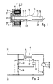
- the gas discharge lamp shown in Fig. 1 consists essentially of a burner vessel 10, which is embedded in a lamp base 11.
- the end Glass or other transparent, temperature resistant Material existing burner vessel 10 has a central combustion chamber 12 with a flattened spherical shape or Ellipsoidgestalt, the opposite Pages two tubular extensions 13, 14 has.
- the End portions of these tubular extensions 13, 14 are as gas-tight current feedthroughs for two main electrodes 15, 16 are formed, coming from both sides slightly into the combustion chamber 12 hineinerglazed. Between These main electrodes 15, 16 are formed during operation the arc out.
- the lamp base 11 is cast or Injection molded body formed and consists of insulating Plastic material. It contains a Zündimpulsschreiber 17, which consists of a ring core 18 and a Winding arrangement 24, 27 for the ring core 18 is made.
- the ring core 18 concentrically surrounds the first tubular extension 13. which is in the lamp base 11 hineinerstreckt, Furthermore, in the lamp base 11 contain electronic components 19, the only schematic are shown and together with the Zündimpulsschreiber 17 form a ballast, the the lamp with the required ignition and burning voltage provided.
- the lamp base 11 also has two annular electrical connections 20, 21, of which the inner with the first main electrode 15 and of those the outer connected to the Zündimpulsschreibtrager 17 is.
- a second connection of the ignition pulse transformer 17 is connected to an outer conduit 22, extending from the lamp base 11 from substantially parallel extends to the burner vessel 10 and at the free End with the second main electrode 16 electrically connected is.
- This outer conduit 22 is as a wire or rod formed.
- the outer conduit 22 to this first Extension 13 led out and forms there an outer Auxiliary electrode 23, thus electrically connected to the second Main electrode 16 is connected.
- This auxiliary electrode 23 can also be used as a conductive strip, e.g.
- the Polarity of the socket-near ersen main electrode 15 is negative with respect to the polarity of the second main electrode 16 and the auxiliary electrode 23 to ensure that after the initial spark, that of the main electrode 15 to the auxiliary electrode 23 through the glass jumps, the sequence spark to the second main electrode 16 without polarity change of the main electrode 15th can follow.
- the Zündimpulsschreibtrager 17, the burner vessel 10, the electronic. Components 19, the electrical Connections 20, 21 and the outer line .22 be together with plastic material to form the Lamp caps 11 overmoulded or potted. With help of the lamp cap 11, the lamp in a socket receptacle for example, a motor vehicle headlight be plugged in.
- Fig. 2 is a possible circuit for a Ballast shown.
- the two electrical connections 20, 21 are via the series connection of a first Winding 24 of Zündimpulsschreibtragers 17 with the two main electrodes 15, 16 of the burner vessel 10 interconnected.
- the two electrical connections 20, 21 via the series circuit a capacitor 25 with a resistor 26 connected.
- Parallel to the capacitor 25 is the series circuit a second winding 27 of the Zündimpulsschreibtragers 17 connected with a spark gap 28.
- the circuit shown in Fig. 2 only one of many known possibilities for such Ballast.
- Other circuits for ballasts of gas discharge lamps are for example in "Lamps and Lighting", 2nd Edition, S.T. Henderson and M. Marsden, p. 328 et seq., and described. From the variety of circuits shown there Ballasts also show, among other things, that the Zündimpulsschreibtrager 17 at some Circuits also designed as a simple throttle or coil can be.
- the lamp base 11 as a prefabricated Housing for receiving the components, such as Zündimpulsschreibtrager 17, burner vessel 10, electrical Components 19, electrical connections 20, 21 and outer Line 22, be formed.
- the Auxiliary electrode 23 also omitted, another shape have or act as a separate ignition voltage Electrode be formed.
Landscapes
- Engineering & Computer Science (AREA)
- General Engineering & Computer Science (AREA)
- Non-Portable Lighting Devices Or Systems Thereof (AREA)
- Common Detailed Techniques For Electron Tubes Or Discharge Tubes (AREA)
Abstract
Description
Aus der DE 43 18 395 A1 ist eine Bogenentladungs- Scheinwerferkapsel bekannt, bei der eine elektrische Baugruppe hinter dem Ende einer Bogenröhre angeordnet ist.
- Fig. 1
- eine Schnittdarstellung der mit einem Lampensockel versehenen Gasentladungslampe als Ausführungsbeispiel und
- Fig. 2
- eine mögliche Ausgestaltung eines Vorschaltgeräts.
Claims (8)
- Gasentladungslampe, insbesondere für Kraftfahrzeug-Scheinwerfer, mit einem wenigstens zwei Elektroden aufweisenden Brennergefäß aus Glas od.dgl., das mit einem elektrische Anschlüsse (20,21) aufweisenden Lampensocke (11) versehen ist, und mit einem elektronischen, die Lampe mit der erforderlichen Zünd- und Brennspannung versorgenden Vorschaltgerät, das im Lampensockel angeordnet ist, wobei der mit dem Vorschaltgerät versehene Lampensockel (11) in eine Sockelaufnahme einsteckbar ausgebildet ist, wobei das Brennergefäß (10) im wesentlichen aus einem Brennraum (12) und zwei sich von diesem aus in entgegengesetzte Richtungen erstreckenden, je eine Hauptelektrode (15, 16) enthaltenden rohrartigen Fortsätzen (13, 14) besteht, wobei die entgegengesetzten Endbereiche der Fortsätze (13, 14) die Elektrodendurchführungen enthalten, und wobei die im vom Lampensockel (11) entfernten Endbereich (14) des Brennergefäßes (10) angeordnete Elektrodendurchführung über eine äußere Leitung (22) zum Lampensockel (11) zurückgeführt und dort mit einem entsprechenden elektrischen Anschluß verbunden ist, dadurch gekennzeichnet, daß ein im Vorschaltgerät enthaltenes induktives Zündbauteil (17), insbesondere ein Zündimpulsübertrager, einen geschlossenen Kern (18) besitzt und daß der geschlossene Kern (18) einen der beiden mit einer Elektrodendurchführung versehenen Endbereiche (13) des Brennergefäßes (10) umgreift.
- Gasentladungslampe nach Anspruch 1, dadurch gekennzeichnet, daß der geschlossene Kern (18) ein Ringkern ist.
- Gasentladungslampe nach einem der vorhergehenden Ansprüche, dadurch gekennzeichnet, daß die für das Vorschaltgerät erforderlichen Bauelemente (17, 19) zusammen mit einem Endbereich (13) des Brennergefäßes (10) wenigstens teilweise mit den Lampensockel (11) bildendem Kunststoffmaterial umspritzt oder vergossen sind.
- Gasentladungslampe nach Anspruch 3, dadurch gekennzeichnet, daß die elektrischen Anschlüsse (20, 21) des Lampensockels ebenfalls mitumspritzt oder mitvergossen sind.
- Gasentladungslampe nach einem der vorhergehenden Ansprüche, dadurch gekennzeichnet, daß die äußere Leitung (22) mit einer Hilfselektrode (23) verbunden ist oder eine solche bildet.
- Gasentladungslampe nach Anspruch 5, dadurch gekennzeichnet, daß die Hilfselektrode (23) in der Nähe der sockelnahen ersten Hauptelektrode (15) angeordnet ist.
- Gasentladungslampe nach Anspruch 5 oder 6, dadurch gekennzeichnet, daß die Hilfselektrode (23) als außen am Brennergefäß (10) anliegender Draht oder leitfähiger Streifen ausgebildet ist.
- Gasentladungslampe nach einem der Ansprüche 5 bis 7, dadurch gekennzeichnet, daß die Polarität der sockelnahen ersten Hauptelektrode (15) negativ ist gegenüber der Polarität der anderen, mit der Hilfselektrode (23) verbundenen zweiten Haupteleklrode (16).
Applications Claiming Priority (3)
| Application Number | Priority Date | Filing Date | Title |
|---|---|---|---|
| DE19610385A DE19610385A1 (de) | 1996-03-16 | 1996-03-16 | Gasentladungslampe, insbesondere für Kraftfahrzeug-Scheinwerfer |
| DE19610385 | 1996-03-16 | ||
| PCT/DE1997/000425 WO1997035336A1 (de) | 1996-03-16 | 1997-03-06 | Gasentladungslampe, insbesondere für kraftfahrzeug-scheinwerfer |
Publications (3)
| Publication Number | Publication Date |
|---|---|
| EP0886882A1 EP0886882A1 (de) | 1998-12-30 |
| EP0886882B1 EP0886882B1 (de) | 2000-05-31 |
| EP0886882B2 true EP0886882B2 (de) | 2005-04-13 |
Family
ID=7788496
Family Applications (1)
| Application Number | Title | Priority Date | Filing Date |
|---|---|---|---|
| EP97916330A Expired - Lifetime EP0886882B2 (de) | 1996-03-16 | 1997-03-06 | Gasentladungslampe, insbesondere für kraftfahrzeug-scheinwerfer |
Country Status (6)
| Country | Link |
|---|---|
| US (1) | US6194834B1 (de) |
| EP (1) | EP0886882B2 (de) |
| JP (1) | JP2000506673A (de) |
| DE (2) | DE19610385A1 (de) |
| ES (1) | ES2148958T3 (de) |
| WO (1) | WO1997035336A1 (de) |
Families Citing this family (23)
| Publication number | Priority date | Publication date | Assignee | Title |
|---|---|---|---|---|
| US5959407A (en) * | 1996-12-07 | 1999-09-28 | Ngk Spark Plug Co., Ltd. | Vehicle lighting drive apparatus |
| DE19803139A1 (de) * | 1998-01-28 | 1999-07-29 | Patent Treuhand Ges Fuer Elektrische Gluehlampen Mbh | Zündvorrichtung für eine Entladungslampe |
| EP1278403B1 (de) * | 1998-05-08 | 2004-04-21 | Denso Corporation | Zündtransformator für Gasentadungslampe |
| DE19831042A1 (de) | 1998-07-13 | 2000-02-17 | Patent Treuhand Ges Fuer Elektrische Gluehlampen Mbh | Beleuchtungssystem mit einer Hochdruckentladungslampe |
| DE19913942C1 (de) * | 1999-03-26 | 2000-04-13 | Vogt Electronic Ag | Gasentladungslampensockel mit Zündeinrichtung |
| JP3316629B2 (ja) * | 1999-05-14 | 2002-08-19 | スタンレー電気株式会社 | 車両用放電灯点灯ユニット |
| FR2795691B1 (fr) † | 1999-07-02 | 2001-08-17 | Valeo Vision | Projecteur de vehicule automobile equipe d'une lampe a decharge et de moyens de blindage electromagnetique perfectionnes |
| DE19939310C2 (de) * | 1999-08-19 | 2001-06-13 | Vogt Electronic Ag | Hochspannungszündmodul |
| WO2001023803A1 (en) * | 1999-09-30 | 2001-04-05 | Matsushita Electric Works, Ltd. | Illumination device |
| US6536918B1 (en) * | 2000-08-23 | 2003-03-25 | General Electric Company | Lighting system for generating pre-determined beam-pattern |
| WO2002051214A1 (de) * | 2000-12-19 | 2002-06-27 | Vogt Electronic Ag | Gasentladungslampensockel mit zündeinrichtung |
| JP2003017283A (ja) * | 2001-06-29 | 2003-01-17 | Ushio Inc | 光源装置 |
| WO2005055272A2 (en) * | 2003-12-02 | 2005-06-16 | Koninklijke Philips Electronics N.V. | High-pressure discharge lamp assembly |
| DE102004056002A1 (de) * | 2004-11-19 | 2006-05-24 | Patent-Treuhand-Gesellschaft für elektrische Glühlampen mbH | Hochdruckentladungslampe mit Impulszündvorrichtung und Betriebsverfahren für eine Hochdruckentladungslampe |
| DE102004055976A1 (de) * | 2004-11-19 | 2006-05-24 | Patent-Treuhand-Gesellschaft für elektrische Glühlampen mbH | Schaltungsanordnung zum Betrieb einer Hochdruckentladungslampe |
| ATE548739T1 (de) | 2006-01-20 | 2012-03-15 | Vogt Electronic Components Gmbh | Zündtransformator und zündmodul für eine entladungsleuchte |
| US7760061B2 (en) * | 2006-08-31 | 2010-07-20 | General Electric Company | Lamp transformer |
| US7855625B2 (en) * | 2006-08-31 | 2010-12-21 | General Electric Company | Lamp transformer |
| US7746211B2 (en) * | 2006-12-27 | 2010-06-29 | General Electric Company | Lamp transformer assembly |
| DE102007017338A1 (de) * | 2007-02-13 | 2008-08-14 | Patent-Treuhand-Gesellschaft für elektrische Glühlampen mbH | Zündtransformator für eine Entladungslampe |
| DE102008059561A1 (de) * | 2008-11-28 | 2010-06-10 | Osram Gesellschaft mit beschränkter Haftung | Integrierte Gasentladungslampe |
| DE102009033068B4 (de) * | 2009-07-03 | 2019-01-17 | SUMIDA Components & Modules GmbH | Ansteuermodul für Gasentladungslampe |
| US8299879B2 (en) * | 2011-02-10 | 2012-10-30 | Leco Corporation | Transformer assembly using an internal load and method for forming same |
Citations (2)
| Publication number | Priority date | Publication date | Assignee | Title |
|---|---|---|---|---|
| DE4318395A1 (de) † | 1992-06-04 | 1993-12-23 | Gte Prod Corp | Belüfteter Gasentladungslampen-Modul für Fahrzeuge |
| EP0717232A2 (de) † | 1994-12-13 | 1996-06-19 | Osram Sylvania Inc. | Entlastungslampe hoher Intensität für einen Kraftfahrzeugscheinwerfer |
Family Cites Families (14)
| Publication number | Priority date | Publication date | Assignee | Title |
|---|---|---|---|---|
| US4097777A (en) * | 1976-11-10 | 1978-06-27 | General Electric Company | Arc discharge lamp including starting circuit |
| US4322658A (en) * | 1980-03-19 | 1982-03-30 | General Electric Company | High intensity discharge lamp containing electronic starting aid |
| NL8006802A (nl) * | 1980-12-16 | 1982-07-16 | Philips Nv | Starter voor het ontsteken van een gas- en/of dampontladingsbuis, alsmede elektrische inrichting en lamp voorzien van een dergelijke starter. |
| HU183313B (en) * | 1981-02-06 | 1984-04-28 | Egyesuelt Izzolampa | Lighting system and electric lighting unit of compact structure |
| EP0150799B1 (de) * | 1984-01-25 | 1989-05-24 | PAROL Leuchtkomponenten GmbH | Montageeinheit für Leuchstofflampen |
| DE3416714A1 (de) * | 1984-05-05 | 1985-11-07 | Philips Patentverwaltung Gmbh, 2000 Hamburg | Hochdruckentladungslampe |
| CA1253913A (en) * | 1984-06-18 | 1989-05-09 | Cornelis A.J. Jacobs | High-pressure sodium discharge lamp |
| DE3519611A1 (de) * | 1985-05-31 | 1986-12-04 | Patent-Treuhand-Gesellschaft für elektrische Glühlampen mbH, 8000 München | Kraftfahrzeugscheinwerfereinheit |
| US5059865A (en) * | 1988-02-18 | 1991-10-22 | General Electric Company | Xenon-metal halide lamp particularly suited for automotive applications |
| EP0391470B1 (de) * | 1989-04-04 | 1994-03-16 | Koninklijke Philips Electronics N.V. | Schaltanordnung |
| EP0576071B1 (de) * | 1992-06-23 | 1996-09-04 | Koninklijke Philips Electronics N.V. | Quecksilberhochdruckentladungslampe |
| US5489825A (en) * | 1992-11-09 | 1996-02-06 | Tunewell Technology Limited | Transformer |
| JPH06314555A (ja) * | 1993-04-30 | 1994-11-08 | Toshiba Lighting & Technol Corp | 高圧放電灯およびこれを用いた投光装置 |
| DE4317368A1 (de) * | 1993-05-25 | 1994-12-01 | Patent Treuhand Ges Fuer Elektrische Gluehlampen Mbh | Verfahren zum Betrieb einer Hochdruckentladungslampe |
-
1996
- 1996-03-16 DE DE19610385A patent/DE19610385A1/de not_active Ceased
-
1997
- 1997-03-06 ES ES97916330T patent/ES2148958T3/es not_active Expired - Lifetime
- 1997-03-06 JP JP9533022A patent/JP2000506673A/ja not_active Abandoned
- 1997-03-06 EP EP97916330A patent/EP0886882B2/de not_active Expired - Lifetime
- 1997-03-06 US US09/142,788 patent/US6194834B1/en not_active Expired - Fee Related
- 1997-03-06 WO PCT/DE1997/000425 patent/WO1997035336A1/de not_active Ceased
- 1997-03-06 DE DE59701814T patent/DE59701814D1/de not_active Expired - Fee Related
Patent Citations (2)
| Publication number | Priority date | Publication date | Assignee | Title |
|---|---|---|---|---|
| DE4318395A1 (de) † | 1992-06-04 | 1993-12-23 | Gte Prod Corp | Belüfteter Gasentladungslampen-Modul für Fahrzeuge |
| EP0717232A2 (de) † | 1994-12-13 | 1996-06-19 | Osram Sylvania Inc. | Entlastungslampe hoher Intensität für einen Kraftfahrzeugscheinwerfer |
Also Published As
| Publication number | Publication date |
|---|---|
| US6194834B1 (en) | 2001-02-27 |
| ES2148958T3 (es) | 2000-10-16 |
| EP0886882A1 (de) | 1998-12-30 |
| WO1997035336A1 (de) | 1997-09-25 |
| EP0886882B1 (de) | 2000-05-31 |
| DE19610385A1 (de) | 1997-09-18 |
| DE59701814D1 (de) | 2000-07-06 |
| JP2000506673A (ja) | 2000-05-30 |
Similar Documents
| Publication | Publication Date | Title |
|---|---|---|
| EP0886882B1 (de) | Gasentladungslampe, insbesondere für kraftfahrzeug-scheinwerfer | |
| EP0203545B1 (de) | Kraftfahrzeugscheinwerfereinheit | |
| DE69812195T2 (de) | Entladungslampeneinheit | |
| DE4310307A1 (de) | Scheinwerfer für Fahrzeuge | |
| DE19610388A1 (de) | Zündeinrichtung für eine Entladungslampe | |
| DE69815457T2 (de) | Betriebsgerät für Entladungslampe | |
| EP1635619B1 (de) | Hochdruckentladungslampe mit Transformator | |
| EP0975007A1 (de) | Beleuchtungssystem mit einer Hochdruckentladungslampe | |
| DE4039689C2 (de) | Entladungslampen-Anordnung in Kraftfahrzeugscheinwerfern | |
| DE19610387A1 (de) | Gasentladungslampe, insbesondere für Kraftfahrzeug-Scheinwerfer | |
| DE2605845A1 (de) | Zuendkerzenstecker | |
| DE68908780T2 (de) | Elektrische Lampe. | |
| DE19624243A1 (de) | Entladungslampe | |
| DE8431386U1 (de) | Adapter für eine einseitig gesockelte Niederdruckentladungslampe | |
| DE10043883A1 (de) | Ummantelung für ein Glühstiftmodul einer Zündspulenanordnung | |
| DE19844293C2 (de) | Beleuchtungseinrichtung | |
| DE3234024C2 (de) | ||
| EP0304037B1 (de) | Zündsystem für Brennkraftmaschinen | |
| DE3544869A1 (de) | Zuendeinheit | |
| DD201955A5 (de) | Hochdruck-natriumdampflampe | |
| DE2822344C2 (de) | Glimmentladungslampe | |
| EP0026733A1 (de) | Vorgefertigter, einteilig winkelförmig gestalteter Muffenkörper | |
| DE19517993A1 (de) | Gasentladungslampe mit Adapter | |
| WO1993010576A1 (de) | Klemme für ein zündgerät | |
| DE7928015U1 (de) | Vorgefertigter elastischer Muffenkörper für kunststoffisolierte geschirmte Starkstromkabel |
Legal Events
| Date | Code | Title | Description |
|---|---|---|---|
| PUAI | Public reference made under article 153(3) epc to a published international application that has entered the european phase |
Free format text: ORIGINAL CODE: 0009012 |
|
| AK | Designated contracting states |
Kind code of ref document: A1 Designated state(s): DE ES FR GB IT SE |
|
| 17P | Request for examination filed |
Effective date: 19981016 |
|
| GRAG | Despatch of communication of intention to grant |
Free format text: ORIGINAL CODE: EPIDOS AGRA |
|
| 17Q | First examination report despatched |
Effective date: 19990712 |
|
| GRAG | Despatch of communication of intention to grant |
Free format text: ORIGINAL CODE: EPIDOS AGRA |
|
| GRAH | Despatch of communication of intention to grant a patent |
Free format text: ORIGINAL CODE: EPIDOS IGRA |
|
| GRAH | Despatch of communication of intention to grant a patent |
Free format text: ORIGINAL CODE: EPIDOS IGRA |
|
| GRAA | (expected) grant |
Free format text: ORIGINAL CODE: 0009210 |
|
| AK | Designated contracting states |
Kind code of ref document: B1 Designated state(s): DE ES FR GB IT SE |
|
| PG25 | Lapsed in a contracting state [announced via postgrant information from national office to epo] |
Ref country code: GB Free format text: LAPSE BECAUSE OF FAILURE TO SUBMIT A TRANSLATION OF THE DESCRIPTION OR TO PAY THE FEE WITHIN THE PRESCRIBED TIME-LIMIT Effective date: 20000531 |
|
| REF | Corresponds to: |
Ref document number: 59701814 Country of ref document: DE Date of ref document: 20000706 |
|
| ITF | It: translation for a ep patent filed | ||
| GBT | Gb: translation of ep patent filed (gb section 77(6)(a)/1977) |
Effective date: 20000727 |
|
| ET | Fr: translation filed | ||
| REG | Reference to a national code |
Ref country code: ES Ref legal event code: FG2A Ref document number: 2148958 Country of ref document: ES Kind code of ref document: T3 |
|
| PLBI | Opposition filed |
Free format text: ORIGINAL CODE: 0009260 |
|
| 26 | Opposition filed |
Opponent name: OSRAM GMBH Effective date: 20010228 |
|
| PLBF | Reply of patent proprietor to notice(s) of opposition |
Free format text: ORIGINAL CODE: EPIDOS OBSO |
|
| REG | Reference to a national code |
Ref country code: GB Ref legal event code: IF02 |
|
| PLBF | Reply of patent proprietor to notice(s) of opposition |
Free format text: ORIGINAL CODE: EPIDOS OBSO |
|
| PGFP | Annual fee paid to national office [announced via postgrant information from national office to epo] |
Ref country code: GB Payment date: 20050223 Year of fee payment: 9 |
|
| PUAH | Patent maintained in amended form |
Free format text: ORIGINAL CODE: 0009272 |
|
| STAA | Information on the status of an ep patent application or granted ep patent |
Free format text: STATUS: PATENT MAINTAINED AS AMENDED |
|
| PGFP | Annual fee paid to national office [announced via postgrant information from national office to epo] |
Ref country code: SE Payment date: 20050323 Year of fee payment: 9 |
|
| 27A | Patent maintained in amended form |
Effective date: 20050413 |
|
| AK | Designated contracting states |
Kind code of ref document: B2 Designated state(s): DE ES FR GB IT SE |
|
| PGFP | Annual fee paid to national office [announced via postgrant information from national office to epo] |
Ref country code: ES Payment date: 20050413 Year of fee payment: 9 |
|
| PGFP | Annual fee paid to national office [announced via postgrant information from national office to epo] |
Ref country code: DE Payment date: 20050513 Year of fee payment: 9 |
|
| PG25 | Lapsed in a contracting state [announced via postgrant information from national office to epo] |
Ref country code: ES Free format text: LAPSE BECAUSE OF FAILURE TO SUBMIT A TRANSLATION OF THE DESCRIPTION OR TO PAY THE FEE WITHIN THE PRESCRIBED TIME-LIMIT Effective date: 20050724 |
|
| GBV | Gb: ep patent (uk) treated as always having been void in accordance with gb section 77(7)/1977 [no translation filed] |
Effective date: 20000531 |
|
| PGFP | Annual fee paid to national office [announced via postgrant information from national office to epo] |
Ref country code: IT Payment date: 20060331 Year of fee payment: 10 |
|
| EN | Fr: translation not filed | ||
| PG25 | Lapsed in a contracting state [announced via postgrant information from national office to epo] |
Ref country code: DE Free format text: LAPSE BECAUSE OF NON-PAYMENT OF DUE FEES Effective date: 20061003 |
|
| PG25 | Lapsed in a contracting state [announced via postgrant information from national office to epo] |
Ref country code: SE Free format text: LAPSE BECAUSE OF NON-PAYMENT OF DUE FEES Effective date: 20060307 |
|
| PGFP | Annual fee paid to national office [announced via postgrant information from national office to epo] |
Ref country code: FR Payment date: 20070331 Year of fee payment: 11 |
|
| PG25 | Lapsed in a contracting state [announced via postgrant information from national office to epo] |
Ref country code: IT Free format text: LAPSE BECAUSE OF NON-PAYMENT OF DUE FEES Effective date: 20070306 |
|
| PG25 | Lapsed in a contracting state [announced via postgrant information from national office to epo] |
Ref country code: FR Free format text: LAPSE BECAUSE OF NON-PAYMENT OF DUE FEES Effective date: 20080330 |