EP0886907B1 - Kompakter elektrischer stellantrieb - Google Patents
Kompakter elektrischer stellantrieb Download PDFInfo
- Publication number
- EP0886907B1 EP0886907B1 EP97914393A EP97914393A EP0886907B1 EP 0886907 B1 EP0886907 B1 EP 0886907B1 EP 97914393 A EP97914393 A EP 97914393A EP 97914393 A EP97914393 A EP 97914393A EP 0886907 B1 EP0886907 B1 EP 0886907B1
- Authority
- EP
- European Patent Office
- Prior art keywords
- piston
- electrically operated
- tubular body
- operated cylinder
- cylinder according
- Prior art date
- Legal status (The legal status is an assumption and is not a legal conclusion. Google has not performed a legal analysis and makes no representation as to the accuracy of the status listed.)
- Expired - Lifetime
Links
Images


Classifications
-
- F—MECHANICAL ENGINEERING; LIGHTING; HEATING; WEAPONS; BLASTING
- F16—ENGINEERING ELEMENTS AND UNITS; GENERAL MEASURES FOR PRODUCING AND MAINTAINING EFFECTIVE FUNCTIONING OF MACHINES OR INSTALLATIONS; THERMAL INSULATION IN GENERAL
- F16H—GEARING
- F16H25/00—Gearings comprising primarily only cams, cam-followers and screw-and-nut mechanisms
- F16H25/18—Gearings comprising primarily only cams, cam-followers and screw-and-nut mechanisms for conveying or interconverting oscillating or reciprocating motions
- F16H25/20—Screw mechanisms
-
- H—ELECTRICITY
- H02—GENERATION; CONVERSION OR DISTRIBUTION OF ELECTRIC POWER
- H02K—DYNAMO-ELECTRIC MACHINES
- H02K7/00—Arrangements for handling mechanical energy structurally associated with dynamo-electric machines, e.g. structural association with mechanical driving motors or auxiliary dynamo-electric machines
- H02K7/06—Means for converting reciprocating motion into rotary motion or vice versa
-
- F—MECHANICAL ENGINEERING; LIGHTING; HEATING; WEAPONS; BLASTING
- F16—ENGINEERING ELEMENTS AND UNITS; GENERAL MEASURES FOR PRODUCING AND MAINTAINING EFFECTIVE FUNCTIONING OF MACHINES OR INSTALLATIONS; THERMAL INSULATION IN GENERAL
- F16H—GEARING
- F16H25/00—Gearings comprising primarily only cams, cam-followers and screw-and-nut mechanisms
- F16H25/18—Gearings comprising primarily only cams, cam-followers and screw-and-nut mechanisms for conveying or interconverting oscillating or reciprocating motions
- F16H25/20—Screw mechanisms
- F16H2025/2062—Arrangements for driving the actuator
- F16H2025/2075—Coaxial drive motors
Definitions
- the present invention relates to an electric actuator, of the type comprising an electric motor, a tubular body comprising a piston and connecting means between the engine and the piston.
- the electric cylinders used until now are actuated by a electric motor placed outside the cylinder body, which ensures, by through a gearbox, the rotational movement of a threaded rod driving the cylinder piston.
- Document DE-C-35 38710 describes a telescopic cylinder according to the prior art in which the electric motor is located inside the cylinder.
- the object of the invention is to propose an electric actuator so arranged to eliminate these drawbacks.
- the invention relates to an electric actuator comprising, as only elements with relative displacement in a direction of actuation of the cylinder, a tubular body and a piston constituted by a tube containing a electric motor slidably mounted inside the tubular body via rotation blocking means which can slide in a longitudinal direction slide of the tubular body and connecting means between the electric motor housed inside the piston and the piston to making the electric motor integral with the piston and cooperating with the wall inside of the tubular body to be able to move the piston and the motor electric in push or pull, the tubular body and the piston being cylindrical and the motor being a geared motor of which one end is integral of the piston and an output shaft is adapted to be able to drive in rotation a nut provided with a thread engaged with an additional thread formed on the inner wall of the tubular body.
- the electric geared motor transmits its rotation to the nut, located in end of the reducer, and which bears directly on the thread of the body of the cylinder.
- Such a structure therefore eliminates the threaded transmission rod the force of the jack and the correlative risks of buckling thereof, since it is the tubular body of the jack which receives the reactions.
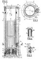
- Figure 1 is a perspective view of a first embodiment of the electric actuator according to the invention, shown in the extended position of the piston.
- Figure 2 is a view in axial longitudinal section of the cylinder of the Figure 1, shown in the retracted position of the piston inside the body.
- Figure 3 is a cross-sectional view along line 3-3 of Figure 2, the gearmotor being removed.
- Figure 4 is a partial elevational view on an enlarged scale along line 4-4 of Figure 3;
- Figure 5 is a partial sectional view on an enlarged scale of a detail in Figure 2.
- Figure 6 is a view similar to Figure 2 of a second form of the electric actuator according to the invention.
- Figure 7 is a half-section along the line 7 of figure 6.
- the electric actuator illustrated in the drawings includes an electric geared motor 1 arranged inside a tubular piston 2 coaxially with the axis longitudinal XX of the latter.
- This piston 2 cylindrical, is itself slidably mounted along the axis XX inside a tubular body 3.
- Piston 2 is closed at one of its ends by a transverse flange 4 to which is fixed a end face of the gearmotor 1. Its opposite end is closed by a plug 5 pierced with a bore 6 for receive a fastener not shown.
- the nut 9 has a central sleeve 9 a enveloping the shaft 8 and is provided with an external thread 11 engaged with a complementary thread 12 formed on the inner wall of the cylindrical body 3 over a length corresponding to the stroke provided for the piston 2.
- the thread 11 and the thread 12 have rectangular sections, preferably square ( Figure 5), with between mating teeth 11 a, 12 a, a large clearance j, that is to say preferably of the order of 0.5 mm approx.
- the nut 9 is fixed to a disc 13 pierced with a central opening and mounted concentrically to a central cylindrical collar 4a of the flange 4 surrounding the sleeve 9 a.
- the nut 9 is secured to the disc 13 by longitudinal screws 14, one of which is visible in FIG. 2.
- Needle bearings 15 are interposed between on the one hand the disc 13 and on the other hand the flange 4 and a nut-ring 16 screwed to the end of the flange 4 a .
- the cylinder is also equipped with means for locking the cylindrical piston 2 in rotation with respect to the body 3.
- these means consist of a tubular stud 17 fixed to the piston 2, extending transversely through the body 3 and able to slide in a longitudinal slide 18 of the body 3.
- the stud 17 is fixed to the piston 2 by screws 17 a and delimits an opening 10 for passage for an electric wire 22.
- a sheath 21 for protecting the electric wire or cable 30 for supplying the gearmotor 1.
- the wire 30 extends inside a helical spring 22 forming a loop 22 has U-into the sheath 21.
- This sheath preferably U shaped as seen in Figure 3, extends longitudinally from one end to the other of the body 3 to which it is fixed by appropriate means, not shown.
- a shutter 23 closes the sheath 21 at the level of the flange 28.
- the sheath 21 receives part of the length of the electric wire 30.
- the two strands of the loop 22 a extend in a plane substantially perpendicular to that of FIG. 2 , as shown in Figure 3.
- the wire 30 extends first from the end of the gear motor 1 facing the plug 5, then between the gear motor 1 and the piston 2 to the tubular stud 17 that it through, through its opening 10, to enter the sheath 21.
- the wire 30 passes through a passage opening 25 in the sheath 21 and a cable gland 24 to be connected to the sector.
- the body 3 On the side opposite the plug 5 of the piston 2, the body 3 is closed by a cover 26 fixed to body 3 for example by screws 27.
- the cylinder is also provided with sealing means.
- the end of the body 3 contiguous to the terminal plug 5 is provided with a ring 28 fixed to the body 3 by screws 20.
- a seal 29 is interposed between the ring 28, the end of the body 3 and the piston 2, this seal 29 being housed in a corresponding body throat 3.
- a second sealing ring 31 and piston guide 2 is housed in the inner wall of the body 3, in order to complete the seal with the piston 2.
- Another seal 32 is advantageously interposed between the cover 26 and the body 3, by being housed in a groove formed in the end of the body 3.
- Wire 30 being connected to the mains power supply, and the gear motor 1 as well the piston 2 being assumed in their positions lower extremities, shown in Figure 2, when the geared motor 1 is actuated in the appropriate direction, its shaft end 8 rotates the nut 9.
- the thread 11 slides with play in the internal thread 12 in exerting a longitudinal thrust on the disc 13. This thrust is transmitted to the flange 4 via the bearings with needles 15, and therefore with tubular piston 2, which starts to come out of the body 3 with its fastener 7 and the interior gear motor 1.
- the wire 30 is driven so that the loop formed by this wire in the sheath 21 is unwound gradually by the transverse stud 17, while remaining protected by the sheath-spring 22, while correspondingly this stud 17 moves in translation in the slide 18.
- the nut 9 is advantageously made of a hard material such as steel, while the tubular body 3 is formed of a composite material with high mechanical strength and very low coefficient of sliding. Such a pair of materials ensures satisfactory sliding between the nut 9 and the body 3.
- the large clearance j mentioned above is reserved between teeth 11a and 12a ( Figure 5). Indeed, a small clearance (for example 0.1 mm), would be likely to cause a jamming of the nut 9 in the body 3 and therefore the blocking of the jack.
- the fact that the thread 11 and the thread 12 have teeth 11 a, 12 a rectangular section, preferably square, has the advantage that in case of failure of the power supply, the nut 9 remains in its position inside the body 3, and does not descend; the piston 2 then remains in the position where it is located.
- piston 2 significantly reduces the size of the entire cylinder and makes it particularly compact.
- this transformation allows to remove the threaded rod from the electric cylinders classics and therefore the correlative risk of buckling of this rod.
- the second embodiment of the jack illustrated in Figures 6 and 7, includes a shirt cylindrical outer 33 enveloping the body 3. On this last is made a longitudinal flat 34 delimiting with the corresponding sector of the shirt 33 a space 35 which contains the spring 22 inside which passes the electric wire 30 forming a loop as in the previous achievement.
- the spring 22 passes through a stud 36 fixed to the piston 2 and able to slide in a longitudinal clearance 37 of the body 3.
- a screw 38 mounted on the pad 36 keeps the spring 22 integral with the latter, while that a second screw 39 passing through the jacket 33 maintains the spring 22 in place in the space 35.
- the jack At its upper end (the cylinder being assumed to be vertical) the jack comprises a sealing ring 41 of the annular interval between the jacket 33 and the plug 5. The seal is ensured by a seal 42 housed between the body 3 and the ring 41.
- a flange 43 is fixed to the jacket 33 and to the cover 26 by screw 44, a seal 45 being interposed between cover 26 and flange 43.
- the electric wire 30 crosses so seals a cable gland 46 in the vicinity of the flange 43.
- the outer jacket 33 preferably in composite material, advantageously fulfills a function sound insulation of the cylinder.
- This cylinder can be easily miniaturized to be suitable for appropriate applications, its possibilities of application being also universal.
Landscapes
- Engineering & Computer Science (AREA)
- General Engineering & Computer Science (AREA)
- Power Engineering (AREA)
- Mechanical Engineering (AREA)
- Connection Of Motors, Electrical Generators, Mechanical Devices, And The Like (AREA)
- Transmission Devices (AREA)
- Pens And Brushes (AREA)
- Cable Accessories (AREA)
- Control Of Motors That Do Not Use Commutators (AREA)
- Braking Arrangements (AREA)
- Valve Device For Special Equipments (AREA)
- Fluid-Damping Devices (AREA)
- Actuator (AREA)
Claims (11)
- Elektrischer Stellantrieb, der als einzige in einer Betatigungsrichtung des Stellantriebs verschiebbare Elemente einen feststehenden rohrförmigen Körper (3) und einen beweglichen Kolben (2) aufweist, der durch ein Rohr gebildet ist, das einen Elektromotor (1) einschließt, das im Innern des rohrförmigen Körpers (3) unter Zwischenanordnung von Drehblockademitteln gleitend angebracht ist, die in einer Gleitbahn in Längsrichtung des rohrförmigen Körpers (3) verschiebbar sind, und Verbindungsmittel (4, 9, 13) zwischen dem Elektromotor (1), der im Innern des Kolbens (2) angeordnet ist, und dem Kolben (2), um den Elektromotor (1) mit dem Kolben (2) fest zu verbinden, wobei sie mit der Innenwand des rohrförmigen Körpers (3) zusammenwirken, um den Kolben (2) und den Elektromotor (1) vorschieben und rückziehen zu können, wobei der rohrförmige Körper (3) und der Kolben (2) zylindrisch sind, und wobei der Motor (1) ein Getriebemotor ist, dessen eines Ende fest mit dem Kolben (2) verbunden ist, und dessen Abtriebswelle (8) dazu ausgelegt ist, eine Nuss (9) in Drehung zu versetzen, die mit einem Außengewinde (11) versehen ist, das im Eingriff mit einem komplementären Innengewinde (12) steht, das in der Innenwand des rohrförmigen Körpers (3) gebildet ist.
- Elektrischer Stellantrieb nach Anspruch 1, dadurch gekennzeichnet, dass die Gewindestege (11a, 12a) des Außengewindes (11) der Nuss (9) und des komplementären Innengewindes (12) des Körpers (3) rechteckigen Querschnitt aufweisen, wobei zwischen den Gewindestegen des Außengewindes ein Spiel (j) bevorzugt in der Größenordnung von ungefähr 0,5 mm vorliegt.
- Elektrischer Stellantrieb nach Anspruch 2, dadurch gekennzeichnet, dass die Nuss (9) an einer Scheibe (13) befestigt ist, die zwischen der Nuss und einem Querflansch (4) des Kolbens (2) angeordnet ist, wobei der Getriebemotor (1) an dem Flansch befestigt ist.
- Elektrischer Stellantrieb nach einem der Ansprüche 1 bis 3, dadurch gekennzeichnet, dass die Nuss (9) aus einem harten Material, wie etwa Stahl besteht, und dass der rohrförmige Körper (3) aus einem Verbundstoffmaterial mit hoher mechanischer Widerstandsfähigkeit und sehr gutem Gleitkoeffizienten besteht.
- Elektrischer Stellantrieb nach einem der Ansprüche 1 bis 4, dadurch gekennzeichnet, dass die Drehblockademittel für den Kolben (2) einen Klotz (17) umfassen, der am Kolben fest angebracht ist und sich quer zum rohrförmigen Körper (3) in der Langsgleitbahn (18) des rohrförmigen Körpers (3) erstreckt.
- Elektrischer Stellantrieb nach Anspruch 5, dadurch gekennzeichnet, dass in der Wand des Körpers (3) ein Schutzschlauch (21) für eine elektrische Leitung (30) zur Stromversorgung des Motors (1) angeordnet ist, die sich im Innern einer Spiralfeder (22) erstreckt, die in dem Schutzschlauch (21) eine Schleife (22a) bildet, und dass dieser Schutzschlauch sich in Längsrichtung erstreckt, um eine Schleife aufzunehmen, die durch einen Teil der Länge der Leitung gebildet ist, so dass diese Schleife sich entrollen oder neu bilden kann, um die Translationsbewegung des Motors (1) und des Kolbens (2) aufzunehmen, und dass Offnungen (10) für den Hindurchtritt der Leitung in dem Körper (3), in der Wand des Kolbens (2) und dem Klotz (17) sowie in dem Schutzschlauch (21) für den Anschluss an das Stromnetz gebildet sind.
- Elektrischer Stellantrieb nach einem der Ansprüche 1 bis 6, dadurch gekennzeichnet, dass er mit Dichtungsmitteln versehen ist.
- Elektrischer Stellantrieb nach Anspruch 7, dadurch gekennzeichnet, dass der Kolben (2) mit einem Abschlussdeckel (5) an seinem Ende in Gegenüberlage zu der Nuss (9) gebildet ist, dass das angrenzende Ende des Körpers (3) mit einem Ring (28) des Kolbens versehen ist, und dass zwischen dem Ring, dem Körper und dem Kolben eine Dichtung (29) angeordnet ist.
- Elektrischer Stellantrieb nach Anspruch 8, dadurch gekennzeichnet, dass das Ende des Körpers (3) in Gegenüberlage zu dem Ring (28) durch einen Deckel (26) gebildet ist, der mit einer Dichtung (32) zwischen dem Deckel und dem Ende des Körpers (2) versehen ist.
- Elektrischer Stellantrieb nach einem der Ansprüche 1 bis 9, dadurch gekennzeichnet, dass die Wand des Körpers (3) einen Außenmantel (33) umfasst, der den rohrförmigen Körper (3) umhüllt.
- Elektrischer Stellantrieb nach Anspruch 10, dadurch gekennzeichnet, dass zwischen dem Mantel (33) und dem Körper (3) ein Raum (35) gebildet ist, der die elektrische Leitung (30) enthält.
Applications Claiming Priority (3)
| Application Number | Priority Date | Filing Date | Title |
|---|---|---|---|
| FR9603172 | 1996-03-13 | ||
| FR9603172A FR2746226B1 (fr) | 1996-03-13 | 1996-03-13 | Verin electrique compact |
| PCT/FR1997/000454 WO1997034356A1 (fr) | 1996-03-13 | 1997-03-13 | Verin electrique compact |
Publications (2)
| Publication Number | Publication Date |
|---|---|
| EP0886907A1 EP0886907A1 (de) | 1998-12-30 |
| EP0886907B1 true EP0886907B1 (de) | 2002-12-04 |
Family
ID=9490153
Family Applications (1)
| Application Number | Title | Priority Date | Filing Date |
|---|---|---|---|
| EP97914393A Expired - Lifetime EP0886907B1 (de) | 1996-03-13 | 1997-03-13 | Kompakter elektrischer stellantrieb |
Country Status (7)
| Country | Link |
|---|---|
| US (1) | US6100609A (de) |
| EP (1) | EP0886907B1 (de) |
| AT (1) | ATE229241T1 (de) |
| CA (1) | CA2248596A1 (de) |
| DE (1) | DE69717608D1 (de) |
| FR (1) | FR2746226B1 (de) |
| WO (1) | WO1997034356A1 (de) |
Families Citing this family (18)
| Publication number | Priority date | Publication date | Assignee | Title |
|---|---|---|---|---|
| US6041308A (en) * | 1996-09-04 | 2000-03-21 | Priceline.Com Incorporated | System and method for motivating submission of conditional purchase offers |
| DE19903718C1 (de) * | 1999-01-30 | 2000-06-29 | Josef Schlattmann | Linearantrieb mit Gewindespindel |
| US6259175B1 (en) * | 1999-11-18 | 2001-07-10 | Dana Corporation | Linear actuator |
| FR2805679B1 (fr) * | 2000-02-25 | 2002-05-31 | Meritor Light Vehicle Sys Ltd | Actionneur a deplacement lineaire perfectionne |
| US6944599B1 (en) | 2000-09-13 | 2005-09-13 | Ebay Inc. | Monitoring and automatic notification of irregular activity in a network-based transaction facility |
| USD502477S1 (en) * | 2002-12-04 | 2005-03-01 | Darryl Beadle | Linear actuator |
| US7675253B2 (en) * | 2006-11-15 | 2010-03-09 | Schlumberger Technology Corporation | Linear actuator using magnetostrictive power element |
| US8820489B2 (en) * | 2007-03-07 | 2014-09-02 | Arvinmeritor Technology, Llc | Electric motor with static brake |
| US8430059B2 (en) | 2008-06-11 | 2013-04-30 | Boston Scientific Scimed, Inc. | Precision pen height control for micro-scale direct writing technology |
| CA2646110A1 (en) * | 2008-11-21 | 2010-05-21 | Ramon B. Gustilo | Bone drill devices, systems and methods |
| US8097987B2 (en) * | 2009-07-31 | 2012-01-17 | Hiwin Mikrosystem Corp. | Movable magnet type linear motor with improved end cover assembly |
| DK177259B1 (da) * | 2010-11-16 | 2012-08-27 | Reac Ab | Røraktuator |
| DE102012014135B4 (de) * | 2012-07-18 | 2024-12-24 | Brose Fahrzeugteile Se & Co. Kommanditgesellschaft, Bamberg | Spindelantrieb |
| USD735666S1 (en) * | 2013-11-01 | 2015-08-04 | Viking Access Systems, Llc | Gate operator housing |
| DE102015208217A1 (de) * | 2015-05-04 | 2016-11-10 | Stabilus Gmbh | Gewindetriebanordnung und Sitzanordnung mit einer Gewindetriebanordnung |
| USD821302S1 (en) * | 2015-06-19 | 2018-06-26 | Dayco Ip Holdings, Llc | Venturi device |
| WO2017019027A1 (en) | 2015-07-28 | 2017-02-02 | Halliburton Energy Services, Inc. | Curved links for wiring conduit |
| CN113726090B (zh) * | 2021-08-10 | 2023-12-08 | 锐迈科技股份有限公司 | 一种电机驱动结构及电机驱动装置 |
Citations (1)
| Publication number | Priority date | Publication date | Assignee | Title |
|---|---|---|---|---|
| DE7215209U (de) * | 1972-12-21 | Hammerl N | Elektrisches Vorschubgerat |
Family Cites Families (8)
| Publication number | Priority date | Publication date | Assignee | Title |
|---|---|---|---|---|
| US3751998A (en) * | 1971-05-18 | 1973-08-14 | A Vasilatos | Linear actuator |
| FR2151646A5 (de) * | 1971-08-31 | 1973-04-20 | Bretagne Atel Chantiers | |
| US4428423A (en) * | 1982-05-06 | 1984-01-31 | Uop Inc. | Well screen end fitting assembly and method of making same |
| US4496921A (en) * | 1982-07-15 | 1985-01-29 | Polaroid Corporation | Electromagnetic actuator having adjustable plunger |
| DE3538710C1 (de) * | 1985-10-31 | 1986-12-18 | Helmut 2420 Eutin Krueger-Beuster | Elektromotorischer Zug- und Schubantrieb |
| US5117700A (en) * | 1991-02-25 | 1992-06-02 | Ross-Hime Designs, Incorporated | Miniature linear actuator |
| DE9412104U1 (de) * | 1994-07-28 | 1994-11-17 | Dewert Antriebs- und Systemtechnik GmbH & Co KG, 32278 Kirchlengern | Elektromotorische Verstelleinrichtung |
| KR0122703Y1 (ko) * | 1994-09-16 | 1998-10-01 | 김광호 | 모터 |
-
1996
- 1996-03-13 FR FR9603172A patent/FR2746226B1/fr not_active Expired - Fee Related
-
1997
- 1997-03-13 EP EP97914393A patent/EP0886907B1/de not_active Expired - Lifetime
- 1997-03-13 AT AT97914393T patent/ATE229241T1/de not_active IP Right Cessation
- 1997-03-13 CA CA002248596A patent/CA2248596A1/fr not_active Abandoned
- 1997-03-13 DE DE69717608T patent/DE69717608D1/de not_active Expired - Lifetime
- 1997-03-13 US US09/142,761 patent/US6100609A/en not_active Expired - Fee Related
- 1997-03-13 WO PCT/FR1997/000454 patent/WO1997034356A1/fr not_active Ceased
Patent Citations (1)
| Publication number | Priority date | Publication date | Assignee | Title |
|---|---|---|---|---|
| DE7215209U (de) * | 1972-12-21 | Hammerl N | Elektrisches Vorschubgerat |
Also Published As
| Publication number | Publication date |
|---|---|
| CA2248596A1 (fr) | 1997-09-18 |
| WO1997034356A1 (fr) | 1997-09-18 |
| ATE229241T1 (de) | 2002-12-15 |
| FR2746226A1 (fr) | 1997-09-19 |
| DE69717608D1 (de) | 2003-01-16 |
| US6100609A (en) | 2000-08-08 |
| FR2746226B1 (fr) | 1998-05-29 |
| EP0886907A1 (de) | 1998-12-30 |
Similar Documents
| Publication | Publication Date | Title |
|---|---|---|
| FR2746226A1 (fr) | Verin electrique compact | |
| WO2016016542A1 (fr) | Réducteur de couple | |
| EP1587205B1 (de) | Spindelantrieb mit einer mit einem Sensor versehenen Kolbenstange | |
| EP1687051A1 (de) | Sicherheitsinjektionsvorrichtung für eine spritze | |
| EP1515051B1 (de) | Stellantrieb mit zwei Betriebsarten | |
| EP1039587A1 (de) | Steckerteil bestimmt für Montage auf einem elektrischen Kabel mit einem schraubenförmig gewellten Aussenleiter und Verfahren zur Montage | |
| FR3072433B1 (fr) | Boitier de transmission et engin roulant equipe d'un tel boitier | |
| CA1311350C (fr) | Procede et dispositif d'extraction d'un troncon de tube d'echangeur dechaleur | |
| FR2662772A1 (fr) | Temoin d'usure pour garniture de friction. | |
| EP0505297A1 (de) | Hydraulischer Zylinder mit Vorrichtung zum Anzeigen der Kolbenstellung | |
| WO2019149540A1 (fr) | Actionneur d'embrayage | |
| EP2039968B1 (de) | Steuervorrichtung mit perfektionierten Abdichtmitteln | |
| FR2969686B1 (fr) | Unite d'entrainement et de transmission, element fonctionnel et montage forme de cette unite et de l'element fonctionnel | |
| WO2025186665A1 (fr) | Actionneur linéaire à indexation interne | |
| WO2021043826A1 (fr) | Vis inversee a billes multi-pistes | |
| FR2765910A1 (fr) | Actionneur de condamnation-decondamnation pour serrure de porte de vehicule automobile, et serrure equipee d'un tel actionneur | |
| FR2681911A1 (fr) | Dispositif de butee pour lanceur de demarreur pour moteur a combustion interne et procede pour la mise en óoeuvre d'un tel dispositif. | |
| EP2037143B1 (de) | Perfektionierte Steuervorrichtung | |
| FR2774744A1 (fr) | Appareil d'eclairage etanche | |
| FR2689875A1 (fr) | Treuil réversible. | |
| FR2879544A1 (fr) | Dispositif de verrouillage d'un frein de stationnement automatique d'un vehicule | |
| FR3025365A1 (fr) | Dispositif d’installation d’une gaine retractable sur un agencement electrique | |
| EP3350491B1 (de) | Vorrichtung zur umwandlung einer schwingbewegung eines zahnrads in eine übersetzungsbewegung eines schiebers und ventil mit solch einer vorrichtung | |
| FR2873170A1 (fr) | Demarreur, notamment de vehicule automobile, equipe d'un lanceur a roue libre par friction | |
| FR2690122A1 (fr) | Ensemble de crémaillère de direction assistée pour véhicule automobile. |
Legal Events
| Date | Code | Title | Description |
|---|---|---|---|
| PUAI | Public reference made under article 153(3) epc to a published international application that has entered the european phase |
Free format text: ORIGINAL CODE: 0009012 |
|
| 17P | Request for examination filed |
Effective date: 19980914 |
|
| AK | Designated contracting states |
Kind code of ref document: A1 Designated state(s): AT BE CH DE DK ES FI FR GB IT LI LU NL SE |
|
| 17Q | First examination report despatched |
Effective date: 19990311 |
|
| GRAG | Despatch of communication of intention to grant |
Free format text: ORIGINAL CODE: EPIDOS AGRA |
|
| GRAG | Despatch of communication of intention to grant |
Free format text: ORIGINAL CODE: EPIDOS AGRA |
|
| GRAH | Despatch of communication of intention to grant a patent |
Free format text: ORIGINAL CODE: EPIDOS IGRA |
|
| GRAH | Despatch of communication of intention to grant a patent |
Free format text: ORIGINAL CODE: EPIDOS IGRA |
|
| GRAA | (expected) grant |
Free format text: ORIGINAL CODE: 0009210 |
|
| AK | Designated contracting states |
Kind code of ref document: B1 Designated state(s): AT BE CH DE DK ES FI FR GB IT LI LU NL SE |
|
| PG25 | Lapsed in a contracting state [announced via postgrant information from national office to epo] |
Ref country code: NL Free format text: LAPSE BECAUSE OF FAILURE TO SUBMIT A TRANSLATION OF THE DESCRIPTION OR TO PAY THE FEE WITHIN THE PRESCRIBED TIME-LIMIT Effective date: 20021204 Ref country code: IT Free format text: LAPSE BECAUSE OF FAILURE TO SUBMIT A TRANSLATION OF THE DESCRIPTION OR TO PAY THE FEE WITHIN THE PRE;WARNING: LAPSES OF ITALIAN PATENTS WITH EFFECTIVE DATE BEFORE 2007 MAY HAVE OCCURRED AT ANY TIME BEFORE 2007. THE CORRECT EFFECTIVE DATE MAY BE DIFFERENT FROM THE ONE RECORDED.SCRIBED TIME-LIMIT Effective date: 20021204 Ref country code: GB Free format text: LAPSE BECAUSE OF FAILURE TO SUBMIT A TRANSLATION OF THE DESCRIPTION OR TO PAY THE FEE WITHIN THE PRESCRIBED TIME-LIMIT Effective date: 20021204 Ref country code: FI Free format text: LAPSE BECAUSE OF FAILURE TO SUBMIT A TRANSLATION OF THE DESCRIPTION OR TO PAY THE FEE WITHIN THE PRESCRIBED TIME-LIMIT Effective date: 20021204 Ref country code: AT Free format text: LAPSE BECAUSE OF FAILURE TO SUBMIT A TRANSLATION OF THE DESCRIPTION OR TO PAY THE FEE WITHIN THE PRESCRIBED TIME-LIMIT Effective date: 20021204 |
|
| REF | Corresponds to: |
Ref document number: 229241 Country of ref document: AT Date of ref document: 20021215 Kind code of ref document: T |
|
| REG | Reference to a national code |
Ref country code: GB Ref legal event code: FG4D Free format text: NOT ENGLISH |
|
| REG | Reference to a national code |
Ref country code: CH Ref legal event code: EP |
|
| REF | Corresponds to: |
Ref document number: 69717608 Country of ref document: DE Date of ref document: 20030116 |
|
| PG25 | Lapsed in a contracting state [announced via postgrant information from national office to epo] |
Ref country code: SE Free format text: LAPSE BECAUSE OF FAILURE TO SUBMIT A TRANSLATION OF THE DESCRIPTION OR TO PAY THE FEE WITHIN THE PRESCRIBED TIME-LIMIT Effective date: 20030304 Ref country code: DK Free format text: LAPSE BECAUSE OF FAILURE TO SUBMIT A TRANSLATION OF THE DESCRIPTION OR TO PAY THE FEE WITHIN THE PRESCRIBED TIME-LIMIT Effective date: 20030304 |
|
| PG25 | Lapsed in a contracting state [announced via postgrant information from national office to epo] |
Ref country code: DE Free format text: LAPSE BECAUSE OF FAILURE TO SUBMIT A TRANSLATION OF THE DESCRIPTION OR TO PAY THE FEE WITHIN THE PRESCRIBED TIME-LIMIT Effective date: 20030305 |
|
| PG25 | Lapsed in a contracting state [announced via postgrant information from national office to epo] |
Ref country code: LU Free format text: LAPSE BECAUSE OF NON-PAYMENT OF DUE FEES Effective date: 20030313 |
|
| PG25 | Lapsed in a contracting state [announced via postgrant information from national office to epo] |
Ref country code: LI Free format text: LAPSE BECAUSE OF NON-PAYMENT OF DUE FEES Effective date: 20030331 Ref country code: CH Free format text: LAPSE BECAUSE OF NON-PAYMENT OF DUE FEES Effective date: 20030331 Ref country code: BE Free format text: LAPSE BECAUSE OF NON-PAYMENT OF DUE FEES Effective date: 20030331 |
|
| NLV1 | Nl: lapsed or annulled due to failure to fulfill the requirements of art. 29p and 29m of the patents act | ||
| GBV | Gb: ep patent (uk) treated as always having been void in accordance with gb section 77(7)/1977 [no translation filed] |
Effective date: 20021204 |
|
| PG25 | Lapsed in a contracting state [announced via postgrant information from national office to epo] |
Ref country code: ES Free format text: LAPSE BECAUSE OF FAILURE TO SUBMIT A TRANSLATION OF THE DESCRIPTION OR TO PAY THE FEE WITHIN THE PRESCRIBED TIME-LIMIT Effective date: 20030627 |
|
| BERE | Be: lapsed |
Owner name: *WERNEST Effective date: 20030331 |
|
| PLBE | No opposition filed within time limit |
Free format text: ORIGINAL CODE: 0009261 |
|
| STAA | Information on the status of an ep patent application or granted ep patent |
Free format text: STATUS: NO OPPOSITION FILED WITHIN TIME LIMIT |
|
| REG | Reference to a national code |
Ref country code: CH Ref legal event code: PL |
|
| 26N | No opposition filed |
Effective date: 20030905 |
|
| PG25 | Lapsed in a contracting state [announced via postgrant information from national office to epo] |
Ref country code: FR Free format text: LAPSE BECAUSE OF NON-PAYMENT OF DUE FEES Effective date: 20031127 |
|
| REG | Reference to a national code |
Ref country code: FR Ref legal event code: ST |