EP0887100B1 - Systeme comprenant un dispositif de filtrage et son dispositif de support - Google Patents
Systeme comprenant un dispositif de filtrage et son dispositif de support Download PDFInfo
- Publication number
- EP0887100B1 EP0887100B1 EP98111760A EP98111760A EP0887100B1 EP 0887100 B1 EP0887100 B1 EP 0887100B1 EP 98111760 A EP98111760 A EP 98111760A EP 98111760 A EP98111760 A EP 98111760A EP 0887100 B1 EP0887100 B1 EP 0887100B1
- Authority
- EP
- European Patent Office
- Prior art keywords
- connections
- filter apparatus
- filter
- nozzles
- housing
- Prior art date
- Legal status (The legal status is an assumption and is not a legal conclusion. Google has not performed a legal analysis and makes no representation as to the accuracy of the status listed.)
- Expired - Lifetime
Links
- 238000001914 filtration Methods 0.000 title description 2
- 239000000835 fiber Substances 0.000 claims abstract description 8
- 239000012528 membrane Substances 0.000 claims abstract 3
- 238000007789 sealing Methods 0.000 claims description 11
- 230000006978 adaptation Effects 0.000 claims description 2
- 239000012530 fluid Substances 0.000 abstract 1
- 239000011324 bead Substances 0.000 description 9
- 238000000502 dialysis Methods 0.000 description 8
- 230000006835 compression Effects 0.000 description 2
- 238000007906 compression Methods 0.000 description 2
- 238000001631 haemodialysis Methods 0.000 description 2
- 230000000322 hemodialysis Effects 0.000 description 2
- 238000002347 injection Methods 0.000 description 2
- 239000007924 injection Substances 0.000 description 2
- 230000013011 mating Effects 0.000 description 2
- 238000004873 anchoring Methods 0.000 description 1
- 238000005266 casting Methods 0.000 description 1
- 238000004891 communication Methods 0.000 description 1
- 230000000295 complement effect Effects 0.000 description 1
- 150000001875 compounds Chemical class 0.000 description 1
- 238000010276 construction Methods 0.000 description 1
- 238000005516 engineering process Methods 0.000 description 1
- 239000007788 liquid Substances 0.000 description 1
- 238000004519 manufacturing process Methods 0.000 description 1
- 239000000463 material Substances 0.000 description 1
- 230000002093 peripheral effect Effects 0.000 description 1
- 230000001954 sterilising effect Effects 0.000 description 1
Images





Classifications
-
- B—PERFORMING OPERATIONS; TRANSPORTING
- B01—PHYSICAL OR CHEMICAL PROCESSES OR APPARATUS IN GENERAL
- B01D—SEPARATION
- B01D61/00—Processes of separation using semi-permeable membranes, e.g. dialysis, osmosis or ultrafiltration; Apparatus, accessories or auxiliary operations specially adapted therefor
- B01D61/24—Dialysis ; Membrane extraction
- B01D61/28—Apparatus therefor
-
- A—HUMAN NECESSITIES
- A61—MEDICAL OR VETERINARY SCIENCE; HYGIENE
- A61M—DEVICES FOR INTRODUCING MEDIA INTO, OR ONTO, THE BODY; DEVICES FOR TRANSDUCING BODY MEDIA OR FOR TAKING MEDIA FROM THE BODY; DEVICES FOR PRODUCING OR ENDING SLEEP OR STUPOR
- A61M1/00—Suction or pumping devices for medical purposes; Devices for carrying-off, for treatment of, or for carrying-over, body-liquids; Drainage systems
- A61M1/14—Dialysis systems; Artificial kidneys; Blood oxygenators ; Reciprocating systems for treatment of body fluids, e.g. single needle systems for hemofiltration or pheresis
- A61M1/16—Dialysis systems; Artificial kidneys; Blood oxygenators ; Reciprocating systems for treatment of body fluids, e.g. single needle systems for hemofiltration or pheresis with membranes
-
- A—HUMAN NECESSITIES
- A61—MEDICAL OR VETERINARY SCIENCE; HYGIENE
- A61M—DEVICES FOR INTRODUCING MEDIA INTO, OR ONTO, THE BODY; DEVICES FOR TRANSDUCING BODY MEDIA OR FOR TAKING MEDIA FROM THE BODY; DEVICES FOR PRODUCING OR ENDING SLEEP OR STUPOR
- A61M1/00—Suction or pumping devices for medical purposes; Devices for carrying-off, for treatment of, or for carrying-over, body-liquids; Drainage systems
- A61M1/14—Dialysis systems; Artificial kidneys; Blood oxygenators ; Reciprocating systems for treatment of body fluids, e.g. single needle systems for hemofiltration or pheresis
- A61M1/16—Dialysis systems; Artificial kidneys; Blood oxygenators ; Reciprocating systems for treatment of body fluids, e.g. single needle systems for hemofiltration or pheresis with membranes
- A61M1/1621—Constructional aspects thereof
- A61M1/1652—Holding or locking systems for the membrane unit
-
- B—PERFORMING OPERATIONS; TRANSPORTING
- B01—PHYSICAL OR CHEMICAL PROCESSES OR APPARATUS IN GENERAL
- B01D—SEPARATION
- B01D63/00—Apparatus in general for separation processes using semi-permeable membranes
- B01D63/02—Hollow fibre modules
-
- B—PERFORMING OPERATIONS; TRANSPORTING
- B01—PHYSICAL OR CHEMICAL PROCESSES OR APPARATUS IN GENERAL
- B01D—SEPARATION
- B01D65/00—Accessories or auxiliary operations, in general, for separation processes or apparatus using semi-permeable membranes
-
- B—PERFORMING OPERATIONS; TRANSPORTING
- B01—PHYSICAL OR CHEMICAL PROCESSES OR APPARATUS IN GENERAL
- B01D—SEPARATION
- B01D69/00—Semi-permeable membranes for separation processes or apparatus characterised by their form, structure or properties; Manufacturing processes specially adapted therefor
- B01D69/08—Hollow fibre membranes
-
- A—HUMAN NECESSITIES
- A61—MEDICAL OR VETERINARY SCIENCE; HYGIENE
- A61M—DEVICES FOR INTRODUCING MEDIA INTO, OR ONTO, THE BODY; DEVICES FOR TRANSDUCING BODY MEDIA OR FOR TAKING MEDIA FROM THE BODY; DEVICES FOR PRODUCING OR ENDING SLEEP OR STUPOR
- A61M2205/00—General characteristics of the apparatus
- A61M2205/12—General characteristics of the apparatus with interchangeable cassettes forming partially or totally the fluid circuit
- A61M2205/125—General characteristics of the apparatus with interchangeable cassettes forming partially or totally the fluid circuit with incorporated filters
-
- A—HUMAN NECESSITIES
- A61—MEDICAL OR VETERINARY SCIENCE; HYGIENE
- A61M—DEVICES FOR INTRODUCING MEDIA INTO, OR ONTO, THE BODY; DEVICES FOR TRANSDUCING BODY MEDIA OR FOR TAKING MEDIA FROM THE BODY; DEVICES FOR PRODUCING OR ENDING SLEEP OR STUPOR
- A61M2209/00—Ancillary equipment
- A61M2209/08—Supports for equipment
- A61M2209/082—Mounting brackets, arm supports for equipment
-
- B—PERFORMING OPERATIONS; TRANSPORTING
- B01—PHYSICAL OR CHEMICAL PROCESSES OR APPARATUS IN GENERAL
- B01D—SEPARATION
- B01D2313/00—Details relating to membrane modules or apparatus
- B01D2313/06—External membrane module supporting or fixing means
-
- B—PERFORMING OPERATIONS; TRANSPORTING
- B01—PHYSICAL OR CHEMICAL PROCESSES OR APPARATUS IN GENERAL
- B01D—SEPARATION
- B01D2313/00—Details relating to membrane modules or apparatus
- B01D2313/13—Specific connectors
- B01D2313/131—Quick connectors or quick-fit
-
- B—PERFORMING OPERATIONS; TRANSPORTING
- B01—PHYSICAL OR CHEMICAL PROCESSES OR APPARATUS IN GENERAL
- B01D—SEPARATION
- B01D2313/00—Details relating to membrane modules or apparatus
- B01D2313/21—Specific headers, end caps
Definitions
- the invention relates to a system consisting of a filter device and a device for holding the filter device, and the filter device for use in such a system and the holder for such a filter device.
- Filter devices of this type which are used for example as dialyzers, hemofilters or ultrafilters, are known in different embodiments.
- Filter devices of this type which are preferably used as dialyzers have been described, for example, in EP 0 441 721 B1 and EP 0 525 317 A1.
- From DE-36 41 843 A1 discloses a hemodialysis apparatus with sterilizing device is known, are used in the filter devices of the type mentioned once as a dialyzer and on the other as a sterile grid for the dialysis.
- Filter devices of the type described above usually consist of pipe-section-shaped housings with end caps, which are provided with two axial and two radial connecting pieces for the liquids to be passed through.
- the connecting pieces are connected to hoses and / or piping systems using standard connections or connectors. These connections are not only often cause by cumbersome manipulation, they also require complex connectors with a complicated connection technology, which make the application more expensive. In addition, the connectors can also cause leakage, which can lead to serious damage to health, especially in hemodialysis.
- EP 0 818 228 A1 which has subsequently been published and is therefore only considered in accordance with Article 54 (3) EPC for Germany, France, Great Britain and Italy, already describes a device for holding filter devices with connections in sealing engagement with the filter device connections in a first position stand. They are displaceable via guide means in a second position in which the terminals are aligned.
- the object of the invention is to provide a system consisting of filter device and corresponding holder and a filter device and provided for the filter device holder of the type specified, which allows a simple and secure connection to a hose or piping system.
- the filter device according to the invention can be easily and quickly connected to a filter or dialysis machine or a housing holding the filter device by plugging in such a way that the connections or connecting pieces are aligned with mating connections or mating connection and anchoring can be merged in sealing manner.
- the connections or connecting pieces and their opposite parts must be coordinated with each other.
- filter devices of the type described are known, which are provided on the tubular portion-shaped housing end caps with mutually parallel and in each case one of the two flow spaces communicating passages, so that the Filtervorrichfitch can be summarized by sealing juxtaposition to filter batteries, in which the individual filter devices are connected in parallel.
- the end caps of the filter devices with the aligned through holes are clamped together by bolts, with closure plates are placed on the outer sides of the cap, wearing the connection piece, as far as the respective ends of the through holes should serve as inputs or outlets.
- the connections may have tube-shaped openings.
- the mouths of the connections can lie in mutually parallel planes or else in a common plane.
- the centerlines of the orifices are conveniently located on a common longitudinal plane which may include the centerline of the housing or may be parallel to the centerline of the housing.
- the orifices may also lie on mutually parallel planes which extend radially to the housing.
- the connections are located on the end caps of the housing.
- the housing which expediently consists of a pipe section, free of terminals, so that the housing wall can be made thin-walled and thus saving material.
- the connections or connecting pieces on the end caps these can be made more robust without burdening the housing itself.
- the end caps are provided with radial, extending over the bottoms of the beads, in which the cap edges protruding ends open the terminals. In this way, a particularly stable construction is given, which holds the rimmed between the caps housing part free of terminals and voltages caused by these.
- the invention further relates to a device for holding filter devices with radial connections, preferably of filter devices of the type described above.
- Filter devices which are usually intended for single use only, must be easily, quickly and safely connected to a filter or dialysis machine and easily and quickly replaced.
- a device for holding filter devices with lateral connections, the center lines of which run parallel to each other, preferably of filter devices of the type described above, is characterized by means for positioning the filtering device in a position relative to the holder in which its connections or connecting pieces aligned with the grommets of the holder, and with the appropriate direction after the ports or connecting pieces sealingly push on the spouts or can be pressed.
- the device may consist of a guide with two guide sections, of which the first serves for placing and positioning of the filter device and the second of the correct position pushing the filter device, so that the terminals or connecting pieces of the filter device with sealing contact are pushed onto the grommets.
- the device may also consist of a pivot bearing for the filter device in which this is hooked to their positioning, so that the filter device can be pressed in the correct position after hanging with their connecting piece on the grommets of the holder.
- the device may also consist of a guide device provided with an actuating device into which the filter device is inserted and which subsequently pushes or presses the filter device in the direction of the holder so that its connections or connecting pieces come into sealing engagement with the grommets.
- a preferred embodiment is characterized by an elongate frame- or box-shaped holding part, which is provided with guides for receiving counter-pieces of the filter devices to their orientation in the transverse direction and the depth and with a stop for their orientation in the longitudinal direction, with extendable spouts are provided , which engage in the aligned state of an attached filter device in sealing in the nozzle.
- the guides consist of grooves whose flanks are provided with grooves parallel to their edges or back slide, engage in the mutually parallel ribs, which are arranged as counter guide pieces laterally of the terminals or nozzles of the filter devices.
- the flanks or edges of the upper groove can be provided with the stop.
- the grommets are arranged on a slider, which in the direction of the longitudinal axes in slidably guided on the holding part, that the slider is loaded in the direction of the patch filter device by at least one resilient element and that a resilient element exciting means is provided, by releasing the grommets snapping into the connections or nozzles of the attached filter device retracted.
- the resilient element exciting device may consist of a toggle or an eccentric, which has been moved in its clamping position in its dead center. If the eccentric or the toggle lever is released from its dead center position, the grommets snapping into the neck of the attached filter device.
- the slider carrying the spouts one side is mounted in a carriage, which is guided limitedly displaceable in the holding part for adaptation to different distances of the end-side connections or nozzles of the filter device.
- the slider may be provided for aligning the carriage with a positioning device which engages a stop of the carriage positioning the filter device.
- the positioning device expediently consists of a pin with an oblique surface, which acts on a stop edge of the filter device.
- the filter device consists of a tubular housing 1, whose ends are enlarged by bell-shaped edge regions 2 in their diameters.
- bell-shaped edge regions 2 On the inside of the bell-shaped widening edge 2, free-projecting, strip-shaped extensions 3 adjoin, which have distributed over the circumference approximately equal distances from each other and are aligned with the cylindrical wall of the housing 1. These strip-shaped projections serve to hold the ends of the fiber bundle, not shown, incorporating casting compounds.
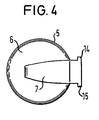
- the mouths of the terminals 8 to 11 are frame-like bordered by the end face of the beads 12, 13, which are provided on their outer sides with outwardly projecting, mutually parallel ribs 14, 15, which serve to anchor to a holding part of a housing with Counter terminals is provided for the connections 8 to 11, wherein the Konnekttechnik the connections can be effected by simply Aufsteck or pushing.
- the housing 1 and the caps 5 are made in the usual way of plastic injection molded parts.
- Fig. 6 is a generally designated as 21 holding part can be seen, which is fixed in a manner not shown on the housing of a filter or dialysis machine.
- the designated throughout with 20 filter device of the type described with reference to FIGS. 1 to 5 is used in such a way that their connections 8 to 9 with retractable spouts of the holding part 21 are tightly connected.
- the holding part 21 consists of a cup-shaped housing 22, the open side of which is connected to the housing of a filter or dialysis apparatus in such a way that its peripheral edge bears against an outer side of a housing wall.
- the cup-shaped housing has a central retraction 23, so that upper and lower housing parts 24, 25 protrude and surround the retracted middle housing part 23.
- aligned grooves 26, 27 are arranged, which leak freely upwardly in a funnel-shaped widening shape.
- the aligned grooves 26, 27 are provided in their opposite flanks with further grooves 28, 29, which outwardly through Edge webs 30, 31 are limited.
- the upper edge webs 30, 31 are provided with step-shaped stops 32.
- the width of the nose-shaped beads 7 of the filter devices 20 immediately before the outer edges forming ribs 14, 15 corresponds to the distance between the edge strips 30, 31 of the grooves 26, 27, so that the filter device from above through the funnel-shaped widening inlets the grooves 26, 27 of the holding part can be inserted in such a way that the ribs are guided in the grooves provided in the flanks 28, 29 and the edge webs 30, 31 of the grooves 26, 27 engage behind.
- the lower spouts 36, 37 are retracted after appropriate alignment in the lower terminals 10, 11.
- the upper spouts 34, 35 are arranged on a slider 40 which is guided longitudinally displaceably on five pins 41 to 45.
- the pins 41 to 45 are screwed into holes in the housing.
- the pins 41 to 44 are provided with widened heads, on which the one ends are supported by compression springs whose other ends rest against the slider 40 and bias it in the direction of the housing 46.
- a shaft 47 is rotatably mounted, which carries an outer lever 48.
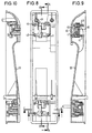
- an eccentric 49 is mounted on the shaft 47, which can roll with its eccentric surface on the adjacent wall of the slider 40 in the manner shown in FIG. 9 way.
- the eccentric 49 can be in its dead center position or rotate over dead center position, in which the slider is moved to the bolt 41 to 45 inwardly, so that the springs are biased even stronger. In this biased form, the filter device 20 is inserted into the grooves 26, 27. Now, if the lever 48 is pivoted inwardly from its upright position, the eccentric 49 snaps into its apparent from Fig. 9 position so that the springs move the slider 40 to the outside and the grommets 34, 35 sealingly with the terminals or nozzles 8, 9th connect, so that the spouts 34, 35 are connected to the nozzle 8, 9.
- the pin 45 which is not enclosed by a compression spring, serves to guide the slider 40 in the housing 21st
- the grommets 36, 37 are arranged on a slider 50 which is guided on the bolts 51 to 55, whose front ends are screwed into the block 56, wherein the bolts 51 to 54 compressive springs, which on the one hand on the widened heads of the bolts and on the other hand supported on the slider 50.
- the additional bolt 55 is used exclusively for guiding the slider 50.
- a shaft 58 is mounted, on which two eccentrics 59, 60 are fixed, which can be seen in Fig. 11 manner on top walls 61, 62 of the slider 50 supported, the lateral recesses of the slider 50 limit ,
- the connected to the slider 50 spouts 36, 37 pass through holes 63, 64 of the pad 36th
- the slider 50 is provided in series with the spouts with a centering pin 65 which passes through the block 56 in a further bore 66.
- the centering pin 65 is provided with a bevel in the manner shown in FIG. 7.
- the spouts 36 and 37 and the centering pin 65 pass through the bottom of the groove 27 in an apparent from Fig. 7 slot 68 in which they are limitedly displaceable.
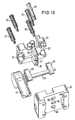
- the block 56 is provided in the manner shown in FIGS. 11 and 12 with lateral runners 69, 70, so that it is limited in the longitudinal direction of the housing 21 in complementary guide grooves slidably.
- the eccentric shaft 59, 60 bearing shaft 58 is provided on the outside of the housing 22 with a lever 72 through which the eccentric shaft is rotatable.
- the two levers 48 and 72 are placed vertically, so that the eccentric bias the sliders 40 and 50 in the manner described and the grommets are in their retracted position. Subsequently, the filter module 20 is inserted into the grooves until the lower edge 33 of the frame-shaped end face of the bead 12 is supported on the stops 32. For connecting the grommets 34, 35 with the terminals 8, 9, the lever 48 is then folded in the manner shown in FIG. 7 manner, so that the grommets 34, 35 snapping and sealing in the terminals 8, 9 retract.
- the lower lever 72 is folded over so that the lower slider extends and retract the spouts 36, 37 snapping into the terminals 10, 11 of the filter module. If due to manufacturing tolerances, the distance of the spouts to the terminals 10, 11 are not accurate, followed by an alignment by the adjusting pin 65, the inclined surface engages the upper edge of the frame-shaped enclosure of the front side of the lower bead 13 of the filter module and 67 via its inclined surface carriage-shaped block 56 lifts so far that the spouts 36, 37 can move into the recesses 10, 11 in alignment.
- the cup-shaped housing 21 For attachment in a housing wall of the filter or dialysis machine, the cup-shaped housing 21 is provided on its rear side with feet which have recesses for connection.
- the cup-shaped housing 21 and the sliders and the carriage-like block 56 may consist of plastic injection molded parts.
Landscapes
- Health & Medical Sciences (AREA)
- Urology & Nephrology (AREA)
- Heart & Thoracic Surgery (AREA)
- Chemical Kinetics & Catalysis (AREA)
- Chemical & Material Sciences (AREA)
- Engineering & Computer Science (AREA)
- Hematology (AREA)
- General Health & Medical Sciences (AREA)
- Anesthesiology (AREA)
- Biomedical Technology (AREA)
- Emergency Medicine (AREA)
- Life Sciences & Earth Sciences (AREA)
- Animal Behavior & Ethology (AREA)
- Vascular Medicine (AREA)
- Public Health (AREA)
- Veterinary Medicine (AREA)
- Water Supply & Treatment (AREA)
- External Artificial Organs (AREA)
- Separation Using Semi-Permeable Membranes (AREA)
- Infusion, Injection, And Reservoir Apparatuses (AREA)
- Electrical Discharge Machining, Electrochemical Machining, And Combined Machining (AREA)
Claims (19)
- Système comprenant
un dispositif de filtrage avec un boîtier (1) allongé avec deux compartiments d'écoulement séparés l'un de l'autre par des membranes avec au moins un raccordement (8 11) ou une tubulure de raccordement agencée radialement, de préférence deux raccordements ou tubulures de raccordement, pour chaque compartiment d'écoulement, les raccordements (8 - 11) étant disposés sur un côte du boîtier (1) et leurs lignes médianes étant parallèles entre elles, des pièces de contre-guidage pourvues d'une butée (33) étant disposées sur le côté des raccordements (8 - 11), appropriées pour l'orientation du dispositif de filtrage dans le sens longitudinal et le sens transversal ainsi que dans la profondeur dans des guides (26, 27) d'une pièce de retenue (21), les pièces de contre-guidage comprenant des nervures (14, 15) débordant vers l'extérieur et parallèles entre elles, et
un dispositif pour le support de ce dispositif de filtrage, avec des douilles (34, 35; 36, 37), qui doivent être mises en prise pour l'étanchéité avec les raccordements (8 - 11) ou les tubulures de raccordement du dispositif de filtrage, et avec un système avec lequel le dispositif de filtrage peut être positionné dans une position par rapport au dispositif de support, dans lequel ses raccordements (8 - 11) ou tubulures de raccordement sont orientés en alignement avec les douilles (34, 35; 36, 37) du dispositif pour le support, le système étant pourvu de moyens de guidage qui garantissent un assemblage consécutif des raccordements (8 - 11) et tubulures de raccordement avec les douilles (34, 35; 36, 37) en ce sens que celles-ci viennent en prise pour l'étanchéité les unes avec les autres, une partie de retenue (21) allongée et en forme de cadre ou de boîtier, qui est pourvue de guides (26, 27) pour le logement de pièces de contre-guidage des dispositifs de filtrage (20) pour leur alignement dans leur sens transversal et dans leur profondeur et d'une butée (32) pour leur orientation dans leur sens longitudinal, les douilles (34, 35; 36, 37) pouvant être sorties et s'engageant, lorsqu'un dispositif de filtrage (20) posé dessus est orienté de façon étanche dans ses raccordements (8 - 11) ou tubulures. - Dispositif de filtrage pour la réalisation dans un Système selon la revendication 1 avec un boîtier (1) allongé
avec deux compartiments d'écoulement séparés l'un de l'autre par des membranes avec au moins un raccordement (8 11) ou tubulure de raccordement agencée radialement, de préférence deux raccordements ou tubulures de raccordement, pour chaque compartiment d'écoulement, les raccordements (8 - 11) étant disposés sur un côté du boîtier (1) et dont les lignes médianes sont parallèles entre elles,
caractérisé en ce que
des pièces de contre-guidage pourvues d'une butée (33) sont disposées sur le côté des raccordements (8 - 11), appropriées pour l'orientation du dispositif de filtrage dans le sens longitudinal et le sens transversal ainsi que dans la profondeur dans des guides (26, 27) d'une partie de retenue (21), les pièces de contre-guidage comprenant des nervures (14, 15) dépassant vers l'extérieur et parallèles entre elles. - Dispositif de filtrage selon la revendication 2, caractérisé en ce que les compartiments d'écoulement séparés sont formés par un faisceau de fibres creuses maintenu dans le boîtier (1), dans lequel les cavités de fibre forment un compartiment d'écoulement et le compartiment entourant le faisceau de fibres l'autre compartiment d'écoulement.
- Dispositif de filtrage selon la revendication 2 ou 3, caractérisé en ce que les raccordements (8 - 11) présentent des orifices en forme de section de tube.
- Dispositif de filtrage selon les revendications 2 à 4, caractérisé en ce que les orifices des raccordements (8 11) sont disposés dans des plans parallèles entre eux.
- Dispositif de filtrage selon l'une quelconque des revendications 2 à 5, caractérisé en ce que les orifices des raccordements (8 - 11) sont disposés dans un plan commun.
- Dispositif de filtrage selon les revendications 2 à 6, caractérisé en ce que les lignes médianes des raccordements (8 - 11) sont disposées sur un plan commun.
- Dispositif de filtrage selon l'une quelconque des revendications 2 à 6, caractérisé en ce que les lignes médianes des raccordements (8 - 11) sont situées sur des plans parallèles entre eux.
- Dispositif de filtrage selon l'une quelconque des revendications 2 à 8, caractérisé en ce que les dispositifs de filtrage présentent des capuchons d'extrémité (5) et en ce que les raccordements (8 - 11) se trouvent sur les capuchons d'extrémité (5).
- Dispositif de filtrage selon l'une quelconque des revendications 2 à 9, caractérisé en ce que le dispositif de filtrage présente des capuchons d'extrémité (5), qui sont conçus en forme de gobelet et qui sont pourvus de respectivement un renflement (7) agencé radialement sur leurs fonds (6), les raccordements (8 - 11) débouchant dans les extrémités, dépassant des bords de capuchon (5), du renflement.
- Dispositif pour le support d'un dispositif de filtrage selon l'une quelconque des revendications 2 à 10, comprenant des douilles (34, 35; 36, 37) qui peuvent être mises en prise pour l'étanchéité avec les raccordements (8 - 11) ou les tubulures de raccordement du dispositif de filtrage, et un système avec lequel le dispositif de filtrage peut être positionné dans une position par rapport au dispositif de support, dans lequel ses raccordements (8 - 11) ou tubulures de raccordement sont orientés en alignement avec les douilles (34, 35; 36, 37) du dispositif de support, le système étant pourvu de moyens de guidage qui garantissent un assemblage consécutif des raccordements (8 - 11) et tubulures de raccordement avec les douilles (34, 35; 36, 37) en ce sens que celles-ci viennent en prise d'étanchéité entre elles, une partie de retenue (21) allongée, en forme de cadre ou de boîtier, qui est pourvue de guides (26, 27) pour le logement de pièces de contre-guidage du dispositif de filtrage (20) pour leur orientation dans leur sens transversal et dans leur profondeur et d'une butée (32) pour leur orientation dans leur sens longitudinal, les douilles (34, 35; 36, 37) prouvant être sorties et s'engageant, lorsque le dispositif de filtrage (20) posé dessus est orienté, de façon étanche dans leurs raccordements (8 - 11) ou tubulures.
- Dispositif selon la revendication 11, caractérisé en ce que les guides se composent de rainures (26, 27), dont les flancs sont dotés de rainures (28, 29) parallèles à leurs bords, dans lesquelles s'engagent des nervures (14, 15) parallèles entre elles, qui sont disposées comme pièces de contre-guidage sur le côté des raccordements ou tubulures (8 - 11) du dispositif de filtrage (20).
- Dispositif selon la revendication 11 ou 12, caractérisé en ce que la partie de retenue (21) présente des rainures (26, 27) disposées dans une position verticale différente et en ce que les flancs ou bords de la rainure (26) supérieure sont dotés de la butée (32).
- Dispositif selon l'une quelconque des revendications 12 à 13, caractérisé en ce que les douilles (34, 35; 36, 37) sont disposées sur une pièce coulissante (40, 50), qui est guidée de façon coulissante en direction de leurs axes longitudinaux dans la partie de retenue (21), que la pièce coulissante (40, 50) est sollicitée en direction du dispositif de filtrage posé dessus par au moins un élément élastique et en ce qu'il est prévu un Dispositif tendant l'élément élastique, par le desserrage duquel les douilles sont engagées par encliquetage dans les raccordements ou tubulures du dispositif de filtrage posé dessus.
- Dispositif selon l'une quelconque des revendications 11 à 14, caractérisé en ce que le dispositif pendant l'élément élastique se compose d'un levier coudé ou d'un excentrique, qui a été déplacé dans sa position de serrage à sa position de point mort.
- Dispositif selon l'une quelconque des revendications 11 à 15, caractérisé en ce que la pièce coulissante (50), portant les douilles, d'un côté est logée dans un bloc (56) en forme de coulisseau, qui est guidé dans la partie de retenue (21) de façon coulissante et limitée pour l'adaptation à différents espacements des raccordements ou tubulures (8 - 11) côté extrémité du dispositif de filtrage.
- Dispositif de filtrage selon l'une quelconque des revendications 11 à 16, caractérisé en ce que la pièce coulissante (50) est dotée d'un système de positionnement (65) pour l'orientation du bloc (56) en forme de coulisseau.
- Dispositif selon la revendication 17, caractérisé en ce que le système de positionnement se compose d'un tenon (65) avec une surface inclinée (67) qui s'applique sur un bord de butée du dispositif de filtrage (20).
Applications Claiming Priority (2)
| Application Number | Priority Date | Filing Date | Title |
|---|---|---|---|
| DE19727251 | 1997-06-26 | ||
| DE19727251A DE19727251C2 (de) | 1997-06-26 | 1997-06-26 | Filtervorrichtung und Vorrichtung zu deren Halterung |
Publications (2)
| Publication Number | Publication Date |
|---|---|
| EP0887100A1 EP0887100A1 (fr) | 1998-12-30 |
| EP0887100B1 true EP0887100B1 (fr) | 2006-01-04 |
Family
ID=7833769
Family Applications (1)
| Application Number | Title | Priority Date | Filing Date |
|---|---|---|---|
| EP98111760A Expired - Lifetime EP0887100B1 (fr) | 1997-06-26 | 1998-06-25 | Systeme comprenant un dispositif de filtrage et son dispositif de support |
Country Status (8)
| Country | Link |
|---|---|
| EP (1) | EP0887100B1 (fr) |
| JP (1) | JP4144938B2 (fr) |
| KR (1) | KR100594472B1 (fr) |
| AT (1) | ATE314884T1 (fr) |
| AU (1) | AU744404B2 (fr) |
| BR (1) | BR9802219B1 (fr) |
| DE (2) | DE19727251C2 (fr) |
| ES (1) | ES2255725T3 (fr) |
Cited By (11)
| Publication number | Priority date | Publication date | Assignee | Title |
|---|---|---|---|---|
| US7195122B2 (en) | 2000-05-12 | 2007-03-27 | Pall Corporation | Filters |
| US7338599B2 (en) | 2000-05-12 | 2008-03-04 | Pall Corporation | Filtration systems and fitting arrangements for filtration systems |
| CN100493634C (zh) * | 2003-02-07 | 2009-06-03 | 甘布罗伦迪亚股份公司 | 支撑元件、集成模块以及装配方法 |
| CN100560145C (zh) * | 2003-02-07 | 2009-11-18 | 甘布罗伦迪亚股份公司 | 体外血液处理机器 |
| US8343346B2 (en) | 2007-09-19 | 2013-01-01 | Fresenius Medical Care Holdings, Inc. | Dialysis systems and related components |
| US8500994B2 (en) | 2010-01-07 | 2013-08-06 | Fresenius Medical Care Holdings, Inc. | Dialysis systems and methods |
| US8506684B2 (en) | 2010-12-15 | 2013-08-13 | Fresenius Medical Care Holdings, Inc. | Gas release devices for extracorporeal fluid circuits and related methods |
| US8663463B2 (en) | 2009-02-18 | 2014-03-04 | Fresenius Medical Care Holdings, Inc. | Extracorporeal fluid circuit and related components |
| US8974405B2 (en) | 2005-10-21 | 2015-03-10 | Fresenius Medical Care Holdings, Inc. | Extracorporeal fluid circuit |
| US9220832B2 (en) | 2010-01-07 | 2015-12-29 | Fresenius Medical Care Holdings, Inc. | Dialysis systems and methods |
| US9375526B2 (en) | 2013-06-25 | 2016-06-28 | Fresenius Medical Care Holdings, Inc. | Vial spiking assemblies and related methods |
Families Citing this family (39)
| Publication number | Priority date | Publication date | Assignee | Title |
|---|---|---|---|---|
| US6378907B1 (en) | 1996-07-12 | 2002-04-30 | Mykrolis Corporation | Connector apparatus and system including connector apparatus |
| DE19925297C1 (de) * | 1999-06-02 | 2000-07-13 | Braun Melsungen Ag | Kartuschenhalter für eine Dialysemaschine |
| ITTO990148U1 (it) * | 1999-07-30 | 2001-01-30 | Hospal Dasco Spa | Unita' di filtrazione per una macchina di dialisi. |
| WO2001064312A1 (fr) | 2000-03-01 | 2001-09-07 | Mykrolis Corporation | Conception d'ensemble jetable a dispositif de separation de fluides et a collecteur susceptible d'etre remplace facilement |
| US9314722B2 (en) | 2000-08-11 | 2016-04-19 | Omnipure Filter Company, Inc. | Keyed system for connection of filter cartridge to filter holder |
| US7476314B2 (en) | 2000-08-11 | 2009-01-13 | Reid Roger P | Keyed system for connection of filter cartridge to filter holder |
| JP2004508183A (ja) | 2000-09-13 | 2004-03-18 | マイクロリス・コーポレイシヨン | 液体濾過装置 |
| US7469932B2 (en) | 2001-09-13 | 2008-12-30 | Entegris, Inc. | Receptor for a separation module |
| JP4731811B2 (ja) | 2001-09-13 | 2011-07-27 | インテグリス・インコーポレーテッド | 分離モジュールおよび固定レセプターを備えたシステムならびに分離モジュール |
| DE10147903C1 (de) * | 2001-09-28 | 2003-04-17 | Fresenius Medical Care De Gmbh | Membranvorrichtung für die Dialyse und/oder Filtration sowie Gehäusemantel einer derartigen Membranvorrichtung |
| WO2003031020A1 (fr) | 2001-10-12 | 2003-04-17 | Reid Roger P | Filtre a changement rapide et systeme d'etrier support |
| TWI269665B (en) | 2002-02-21 | 2007-01-01 | Roger P Reid | Quick change filter and bracket system with key system and universal key option |
| WO2004000391A1 (fr) | 2002-06-24 | 2003-12-31 | Gambro Lundia Ab | Dispositifs de separation de gaz |
| US7247146B2 (en) | 2003-02-07 | 2007-07-24 | Gambro Lundia Ab | Support element for an integrated blood treatment module, integrated blood treatment module and extracorporeal blood treatment apparatus equipped with said integrated module |
| US7223338B2 (en) | 2003-02-07 | 2007-05-29 | Gambro Lundia Ab | Support element for an integrated module for blood treatment, an integrated module for blood treatment, and a manufacturing process for an integrated module for blood treatment |
| US7232418B2 (en) | 2003-02-07 | 2007-06-19 | Gambro Lundia Ab | Support element, an integrated module for extracorporeal blood treatment comprising the support element, an apparatus for extracorporeal blood treatment equipped with the integrated module, and an assembly process for an integrated module for extracorporeal blood treatment |
| US7314554B2 (en) | 2003-02-07 | 2008-01-01 | Gambro Lundia Ab | Extracorporeal blood treatment machine |
| US7223336B2 (en) | 2003-02-07 | 2007-05-29 | Gambro Lundia Ab | Integrated blood treatment module and extracorporeal blood treatment apparatus |
| ITMI20030215A1 (it) * | 2003-02-07 | 2004-08-08 | Gambro Lundia Ab | Elemento di supporto, modulo integrato per il trattamento extracorporeo di sangue comprendente tale elemento di |
| ITMO20040180A1 (it) | 2004-07-14 | 2004-10-14 | Gambo Lidia Ab | Dispositivo di separazione e supporto per un dispositivo di separazione. |
| DE102007017388B4 (de) * | 2007-04-05 | 2012-03-22 | Brita Gmbh | Vorrichtung zur Behandlung von Wasser, insbesondere Filtervorrichtung, und Kartusche |
| CN101980762B (zh) | 2008-03-27 | 2014-02-26 | 株式会社久保田 | 膜组件以及膜盒 |
| USD712007S1 (en) | 2010-03-03 | 2014-08-26 | Omnipure Filter Company, Inc. | Filter for liquid |
| EP2377570B1 (fr) | 2010-04-13 | 2013-09-11 | Gambro Lundia AB | Connecteur pour ligne de transport de fluide d'un dispositif médical |
| SE537186C2 (sv) | 2011-02-17 | 2015-02-24 | Komatsu Forest Ab | Mätanordning för diametermätning av timmerstammar vid skördaraggregat |
| RU2015117532A (ru) | 2012-10-09 | 2016-12-10 | Торэй Индастриз, Инк. | Затычка, медицинский модуль и медицинская система |
| JP6496949B2 (ja) * | 2014-02-28 | 2019-04-10 | 株式会社ハイレックスコーポレーション | 流体処理器着脱装置 |
| JP6337557B2 (ja) * | 2014-03-25 | 2018-06-06 | 株式会社ジェイ・エム・エス | 濾過フィルタ用ホルダ |
| JP6376455B2 (ja) * | 2014-08-29 | 2018-08-22 | 澁谷工業株式会社 | 人工透析装置の濾過器支持装置 |
| US9974942B2 (en) | 2015-06-19 | 2018-05-22 | Fresenius Medical Care Holdings, Inc. | Non-vented vial drug delivery |
| KR101688069B1 (ko) * | 2015-10-26 | 2016-12-20 | 이옥재 | 바이러스검사에 이용되는 필터모듈을 지지하는 스탠드 |
| DE102015120218A1 (de) | 2015-11-23 | 2017-05-24 | B. Braun Avitum Ag | Dialysemaschine mit integrierter Dialysatorkupplung |
| US9945838B2 (en) | 2015-12-17 | 2018-04-17 | Fresenius Medical Care Holdings, Inc. | Extracorporeal circuit blood chamber having an integrated deaeration device |
| GB201701107D0 (en) | 2017-01-23 | 2017-03-08 | Parker Hannifin Mfg (Uk) Ltd | A filter assembly |
| GB201701108D0 (en) * | 2017-01-23 | 2017-03-08 | Parker Hannifin Mfg (Uk) Ltd | A filter assembly |
| DE102017114528A1 (de) * | 2017-06-29 | 2019-01-03 | B. Braun Avitum Ag | Vorrichtung zur extrakorporalen Blutbehandlung mit verbesserter Anordnung einer Blutbehandlungsvorrichtung |
| DE102017214263A1 (de) | 2017-08-16 | 2019-02-21 | Fresenius Medical Care Deutschland Gmbh | Anschlussvorrichtung für ein rohrförmiges filtermodul |
| EP3623037B1 (fr) * | 2018-09-12 | 2021-10-27 | Manfred Völker | Système de filtrage avec un filtre et un porte-filtre comprenant un système de fixation |
| IT201900017207A1 (it) * | 2019-09-25 | 2021-03-25 | Fil Tech Srl | Gruppo filtrante con sistema di montaggio frontale e relativo apparato di filtrazione |
Citations (4)
| Publication number | Priority date | Publication date | Assignee | Title |
|---|---|---|---|---|
| US4231871A (en) * | 1977-06-10 | 1980-11-04 | Cordis Dow Corp. | Artificial kidney and method for making same |
| US5342518A (en) * | 1990-02-14 | 1994-08-30 | Iraco Filtration Systems, Inc. | Filtration system and mount for beverage dispensers and automatic beverage brewing machines |
| JPH105746A (ja) * | 1996-06-20 | 1998-01-13 | Osaka Sanai:Kk | 浄水器とその切替えコック |
| EP0818228A1 (fr) * | 1996-07-12 | 1998-01-14 | Millipore Corporation | Module de séparation à usage unique avec l'aptitude de connexion rapide |
Family Cites Families (8)
| Publication number | Priority date | Publication date | Assignee | Title |
|---|---|---|---|---|
| US35252A (en) * | 1862-05-13 | Improvement in sevving-machines | ||
| US626761A (en) * | 1899-06-13 | Rock-drilling engine | ||
| SE396887B (sv) * | 1976-02-16 | 1977-10-10 | Gambro Ab | Anordning for diffusion av emnen mellan tva fluida via semipermeabla membran |
| US4594161A (en) * | 1982-09-06 | 1986-06-10 | Yamato Scientific Co., Ltd. | Reverse osmosis sealing means |
| AU585177B2 (en) * | 1986-09-12 | 1989-06-08 | U.S. Filter Wastewater Group, Inc. | Hollow fibre filter cartridge and header |
| FR2658080A1 (fr) * | 1990-02-09 | 1991-08-16 | Hospal Ind | Appareil a fibres creuses. |
| SE502103C2 (sv) * | 1991-08-01 | 1995-08-14 | Gambro Dialysatoren | Filterenhet för överföring av massa och/eller värme innehållande hålrumsfibrer |
| US5626761A (en) * | 1993-12-17 | 1997-05-06 | Poly-Bio-Marine, Inc. | Chemical and particulate filtration system/apparatus |
-
1997
- 1997-06-26 DE DE19727251A patent/DE19727251C2/de not_active Expired - Lifetime
-
1998
- 1998-06-12 AU AU70078/98A patent/AU744404B2/en not_active Revoked
- 1998-06-24 KR KR1019980023858A patent/KR100594472B1/ko not_active Expired - Lifetime
- 1998-06-25 BR BRPI9802219-9A patent/BR9802219B1/pt not_active IP Right Cessation
- 1998-06-25 ES ES98111760T patent/ES2255725T3/es not_active Expired - Lifetime
- 1998-06-25 AT AT98111760T patent/ATE314884T1/de active
- 1998-06-25 EP EP98111760A patent/EP0887100B1/fr not_active Expired - Lifetime
- 1998-06-25 DE DE59813324T patent/DE59813324D1/de not_active Expired - Lifetime
- 1998-06-26 JP JP18085298A patent/JP4144938B2/ja not_active Expired - Lifetime
Patent Citations (4)
| Publication number | Priority date | Publication date | Assignee | Title |
|---|---|---|---|---|
| US4231871A (en) * | 1977-06-10 | 1980-11-04 | Cordis Dow Corp. | Artificial kidney and method for making same |
| US5342518A (en) * | 1990-02-14 | 1994-08-30 | Iraco Filtration Systems, Inc. | Filtration system and mount for beverage dispensers and automatic beverage brewing machines |
| JPH105746A (ja) * | 1996-06-20 | 1998-01-13 | Osaka Sanai:Kk | 浄水器とその切替えコック |
| EP0818228A1 (fr) * | 1996-07-12 | 1998-01-14 | Millipore Corporation | Module de séparation à usage unique avec l'aptitude de connexion rapide |
Cited By (12)
| Publication number | Priority date | Publication date | Assignee | Title |
|---|---|---|---|---|
| US7195122B2 (en) | 2000-05-12 | 2007-03-27 | Pall Corporation | Filters |
| US7338599B2 (en) | 2000-05-12 | 2008-03-04 | Pall Corporation | Filtration systems and fitting arrangements for filtration systems |
| CN100493634C (zh) * | 2003-02-07 | 2009-06-03 | 甘布罗伦迪亚股份公司 | 支撑元件、集成模块以及装配方法 |
| CN100560145C (zh) * | 2003-02-07 | 2009-11-18 | 甘布罗伦迪亚股份公司 | 体外血液处理机器 |
| US8974405B2 (en) | 2005-10-21 | 2015-03-10 | Fresenius Medical Care Holdings, Inc. | Extracorporeal fluid circuit |
| US8343346B2 (en) | 2007-09-19 | 2013-01-01 | Fresenius Medical Care Holdings, Inc. | Dialysis systems and related components |
| US8663463B2 (en) | 2009-02-18 | 2014-03-04 | Fresenius Medical Care Holdings, Inc. | Extracorporeal fluid circuit and related components |
| US8500994B2 (en) | 2010-01-07 | 2013-08-06 | Fresenius Medical Care Holdings, Inc. | Dialysis systems and methods |
| US9220832B2 (en) | 2010-01-07 | 2015-12-29 | Fresenius Medical Care Holdings, Inc. | Dialysis systems and methods |
| US8506684B2 (en) | 2010-12-15 | 2013-08-13 | Fresenius Medical Care Holdings, Inc. | Gas release devices for extracorporeal fluid circuits and related methods |
| US9375526B2 (en) | 2013-06-25 | 2016-06-28 | Fresenius Medical Care Holdings, Inc. | Vial spiking assemblies and related methods |
| US9433721B2 (en) | 2013-06-25 | 2016-09-06 | Fresenius Medical Care Holdings, Inc. | Vial spiking assemblies and related methods |
Also Published As
| Publication number | Publication date |
|---|---|
| BR9802219A (pt) | 1999-10-26 |
| KR19990007277A (ko) | 1999-01-25 |
| JP4144938B2 (ja) | 2008-09-03 |
| BR9802219B1 (pt) | 2009-01-13 |
| AU744404B2 (en) | 2002-02-21 |
| DE19727251A1 (de) | 1999-01-07 |
| JPH1170164A (ja) | 1999-03-16 |
| KR100594472B1 (ko) | 2006-10-19 |
| DE59813324D1 (de) | 2006-03-30 |
| DE19727251C2 (de) | 2002-06-06 |
| ES2255725T3 (es) | 2006-07-01 |
| AU7007898A (en) | 1999-01-07 |
| EP0887100A1 (fr) | 1998-12-30 |
| ATE314884T1 (de) | 2006-02-15 |
Similar Documents
| Publication | Publication Date | Title |
|---|---|---|
| EP0887100B1 (fr) | Systeme comprenant un dispositif de filtrage et son dispositif de support | |
| DE3636846C2 (fr) | ||
| DE19925297C1 (de) | Kartuschenhalter für eine Dialysemaschine | |
| DE69704347T2 (de) | Modulares filtrationssystem und verfahren zur zusammensetzung | |
| DE3202446C2 (de) | Klemm- und Verbindungsvorrichtung | |
| DE68911842T2 (de) | Filtersystem. | |
| DE69130393T2 (de) | Modulare, mikroporöse filteranlagen | |
| DE3237213A1 (de) | Duese mit schnelltrennkupplung | |
| DE9000879U1 (de) | Hohlfaser-Blutoxigenator | |
| EP0982609B1 (fr) | Douille pour connection d'un guide d'onde optique et connection | |
| EP0924453A1 (fr) | Raccord de conduit détachable, en particulier pour les conduits de transport d'air | |
| DE10147903C1 (de) | Membranvorrichtung für die Dialyse und/oder Filtration sowie Gehäusemantel einer derartigen Membranvorrichtung | |
| DE3025888C2 (de) | Koppelvorrichtung mit Klemmbrücken für in Stecker gefaßte Lichtleitfasern | |
| DE2814095B2 (de) | Verbinder für zwei sich kreuzende, übereinanderliegende Schienen | |
| DE4032515A1 (de) | Modular zusammensetzbares druckluftaufbereitungssystem fuer eine pneumatik | |
| EP1044094B1 (fr) | Dispositif pour filtrer des matieres plastiques en fusion avec changement des paquets de filtres | |
| DE69733917T2 (de) | Adapter zum Verbinden von optischen Fasern | |
| DE3625074C2 (fr) | ||
| EP0040258A1 (fr) | Collier de serrage en matière plastique | |
| DE3435883A1 (de) | Dialysator | |
| DE2201053C3 (de) | Eckverbinder für auf Gehrung geschnittene Profile oder Rohre | |
| DE2652856C2 (de) | Stoffaustauscher für medizinische Zwecke | |
| DE1536852C (fr) | ||
| DE2842012A1 (de) | Anordnung zur herstellung einer optischen signaluebertragungsverbindung zwischen den stosseitigen enden von zwei optischen fasern | |
| DE62880T1 (de) | Ventil-verbindungselement. |
Legal Events
| Date | Code | Title | Description |
|---|---|---|---|
| PUAI | Public reference made under article 153(3) epc to a published international application that has entered the european phase |
Free format text: ORIGINAL CODE: 0009012 |
|
| AK | Designated contracting states |
Kind code of ref document: A1 Designated state(s): AT BE CH DE ES FR GB IT LI NL |
|
| AX | Request for extension of the european patent |
Free format text: AL;LT;LV;MK;RO;SI |
|
| 17P | Request for examination filed |
Effective date: 19990322 |
|
| AKX | Designation fees paid |
Free format text: AT BE CH DE ES FR GB IT LI NL |
|
| RAP1 | Party data changed (applicant data changed or rights of an application transferred) |
Owner name: FRESENIUS MEDICAL CARE DEUTSCHLAND GMBH |
|
| 17Q | First examination report despatched |
Effective date: 20030227 |
|
| GRAP | Despatch of communication of intention to grant a patent |
Free format text: ORIGINAL CODE: EPIDOSNIGR1 |
|
| RIC1 | Information provided on ipc code assigned before grant |
Ipc: 7A 61M 1/18 B Ipc: 7B 01D 65/00 B Ipc: 7B 01D 63/02 A |
|
| RTI1 | Title (correction) |
Free format text: SYSTEM COMPRISING A FILTRATION DEVICE AND A SUPPORT DEVICE THEREFOR |
|
| GRAS | Grant fee paid |
Free format text: ORIGINAL CODE: EPIDOSNIGR3 |
|
| GRAA | (expected) grant |
Free format text: ORIGINAL CODE: 0009210 |
|
| AK | Designated contracting states |
Kind code of ref document: B1 Designated state(s): AT BE CH DE ES FR GB IT LI NL |
|
| REG | Reference to a national code |
Ref country code: GB Ref legal event code: FG4D Free format text: NOT ENGLISH |
|
| REG | Reference to a national code |
Ref country code: CH Ref legal event code: EP |
|
| REG | Reference to a national code |
Ref country code: CH Ref legal event code: NV Representative=s name: BOVARD AG PATENTANWAELTE |
|
| GBT | Gb: translation of ep patent filed (gb section 77(6)(a)/1977) |
Effective date: 20060223 |
|
| REF | Corresponds to: |
Ref document number: 59813324 Country of ref document: DE Date of ref document: 20060330 Kind code of ref document: P |
|
| REG | Reference to a national code |
Ref country code: ES Ref legal event code: FG2A Ref document number: 2255725 Country of ref document: ES Kind code of ref document: T3 |
|
| ET | Fr: translation filed | ||
| PLBE | No opposition filed within time limit |
Free format text: ORIGINAL CODE: 0009261 |
|
| STAA | Information on the status of an ep patent application or granted ep patent |
Free format text: STATUS: NO OPPOSITION FILED WITHIN TIME LIMIT |
|
| 26N | No opposition filed |
Effective date: 20061005 |
|
| REG | Reference to a national code |
Ref country code: CH Ref legal event code: PFA Owner name: FRESENIUS MEDICAL CARE DEUTSCHLAND GMBH Free format text: FRESENIUS MEDICAL CARE DEUTSCHLAND GMBH#ELSE-KROENER-STRASSE 1#61352 BAD HOMBURG (DE) -TRANSFER TO- FRESENIUS MEDICAL CARE DEUTSCHLAND GMBH#ELSE-KROENER-STRASSE 1#61352 BAD HOMBURG (DE) |
|
| REG | Reference to a national code |
Ref country code: FR Ref legal event code: PLFP Year of fee payment: 19 |
|
| REG | Reference to a national code |
Ref country code: FR Ref legal event code: PLFP Year of fee payment: 20 |
|
| PGFP | Annual fee paid to national office [announced via postgrant information from national office to epo] |
Ref country code: NL Payment date: 20170524 Year of fee payment: 20 |
|
| PGFP | Annual fee paid to national office [announced via postgrant information from national office to epo] |
Ref country code: CH Payment date: 20170526 Year of fee payment: 20 Ref country code: GB Payment date: 20170526 Year of fee payment: 20 Ref country code: DE Payment date: 20170522 Year of fee payment: 20 Ref country code: FR Payment date: 20170523 Year of fee payment: 20 |
|
| PGFP | Annual fee paid to national office [announced via postgrant information from national office to epo] |
Ref country code: IT Payment date: 20170522 Year of fee payment: 20 Ref country code: BE Payment date: 20170524 Year of fee payment: 20 Ref country code: AT Payment date: 20170523 Year of fee payment: 20 |
|
| PGFP | Annual fee paid to national office [announced via postgrant information from national office to epo] |
Ref country code: ES Payment date: 20170703 Year of fee payment: 20 |
|
| REG | Reference to a national code |
Ref country code: DE Ref legal event code: R071 Ref document number: 59813324 Country of ref document: DE |
|
| REG | Reference to a national code |
Ref country code: NL Ref legal event code: MK Effective date: 20180624 |
|
| REG | Reference to a national code |
Ref country code: CH Ref legal event code: PL |
|
| REG | Reference to a national code |
Ref country code: GB Ref legal event code: PE20 Expiry date: 20180624 |
|
| PG25 | Lapsed in a contracting state [announced via postgrant information from national office to epo] |
Ref country code: GB Free format text: LAPSE BECAUSE OF EXPIRATION OF PROTECTION Effective date: 20180624 |
|
| REG | Reference to a national code |
Ref country code: AT Ref legal event code: MK07 Ref document number: 314884 Country of ref document: AT Kind code of ref document: T Effective date: 20180625 |
|
| REG | Reference to a national code |
Ref country code: BE Ref legal event code: MK Effective date: 20180625 |
|
| REG | Reference to a national code |
Ref country code: ES Ref legal event code: FD2A Effective date: 20200904 |
|
| PG25 | Lapsed in a contracting state [announced via postgrant information from national office to epo] |
Ref country code: ES Free format text: LAPSE BECAUSE OF EXPIRATION OF PROTECTION Effective date: 20180626 |