EP0887251B1 - Calculateur de bicyclette - Google Patents
Calculateur de bicyclette Download PDFInfo
- Publication number
- EP0887251B1 EP0887251B1 EP98111009A EP98111009A EP0887251B1 EP 0887251 B1 EP0887251 B1 EP 0887251B1 EP 98111009 A EP98111009 A EP 98111009A EP 98111009 A EP98111009 A EP 98111009A EP 0887251 B1 EP0887251 B1 EP 0887251B1
- Authority
- EP
- European Patent Office
- Prior art keywords
- processing unit
- sensor
- bicycle
- main unit
- data
- Prior art date
- Legal status (The legal status is an assumption and is not a legal conclusion. Google has not performed a legal analysis and makes no representation as to the accuracy of the status listed.)
- Expired - Lifetime
Links
- 230000008054 signal transmission Effects 0.000 claims description 8
- 230000001360 synchronised effect Effects 0.000 claims description 8
- 230000007246 mechanism Effects 0.000 claims description 3
- 230000004962 physiological condition Effects 0.000 claims description 2
- 230000005540 biological transmission Effects 0.000 claims 1
- 239000002184 metal Substances 0.000 description 10
- 238000010586 diagram Methods 0.000 description 5
- 238000006243 chemical reaction Methods 0.000 description 3
- 238000004519 manufacturing process Methods 0.000 description 2
- 101001084254 Homo sapiens Peptidyl-tRNA hydrolase 2, mitochondrial Proteins 0.000 description 1
- 102100030867 Peptidyl-tRNA hydrolase 2, mitochondrial Human genes 0.000 description 1
- 101100272590 Saccharomyces cerevisiae (strain ATCC 204508 / S288c) BIT2 gene Proteins 0.000 description 1
- 238000010276 construction Methods 0.000 description 1
- 230000001419 dependent effect Effects 0.000 description 1
- 238000000034 method Methods 0.000 description 1
- 238000012986 modification Methods 0.000 description 1
- 230000004048 modification Effects 0.000 description 1
- 230000008569 process Effects 0.000 description 1
- XLYOFNOQVPJJNP-UHFFFAOYSA-N water Substances O XLYOFNOQVPJJNP-UHFFFAOYSA-N 0.000 description 1
Images


Classifications
-
- G—PHYSICS
- G01—MEASURING; TESTING
- G01D—MEASURING NOT SPECIALLY ADAPTED FOR A SPECIFIC VARIABLE; ARRANGEMENTS FOR MEASURING TWO OR MORE VARIABLES NOT COVERED IN A SINGLE OTHER SUBCLASS; TARIFF METERING APPARATUS; MEASURING OR TESTING NOT OTHERWISE PROVIDED FOR
- G01D21/00—Measuring or testing not otherwise provided for
- G01D21/02—Measuring two or more variables by means not covered by a single other subclass
-
- B—PERFORMING OPERATIONS; TRANSPORTING
- B62—LAND VEHICLES FOR TRAVELLING OTHERWISE THAN ON RAILS
- B62J—CYCLE SADDLES OR SEATS; AUXILIARY DEVICES OR ACCESSORIES SPECIALLY ADAPTED TO CYCLES AND NOT OTHERWISE PROVIDED FOR, e.g. ARTICLE CARRIERS OR CYCLE PROTECTORS
- B62J45/00—Electrical equipment arrangements specially adapted for use as accessories on cycles, not otherwise provided for
- B62J45/20—Cycle computers as cycle accessories
-
- B—PERFORMING OPERATIONS; TRANSPORTING
- B62—LAND VEHICLES FOR TRAVELLING OTHERWISE THAN ON RAILS
- B62J—CYCLE SADDLES OR SEATS; AUXILIARY DEVICES OR ACCESSORIES SPECIALLY ADAPTED TO CYCLES AND NOT OTHERWISE PROVIDED FOR, e.g. ARTICLE CARRIERS OR CYCLE PROTECTORS
- B62J50/00—Arrangements specially adapted for use on cycles not provided for in main groups B62J1/00 - B62J45/00
- B62J50/20—Information-providing devices
- B62J50/21—Information-providing devices intended to provide information to rider or passenger
- B62J50/22—Information-providing devices intended to provide information to rider or passenger electronic, e.g. displays
-
- G—PHYSICS
- G01—MEASURING; TESTING
- G01P—MEASURING LINEAR OR ANGULAR SPEED, ACCELERATION, DECELERATION, OR SHOCK; INDICATING PRESENCE, ABSENCE, OR DIRECTION, OF MOVEMENT
- G01P1/00—Details of instruments
- G01P1/07—Indicating devices, e.g. for remote indication
Definitions
- the present invention relates to a bicycle cycle computer for displaying various kinds of information regarding the speed, the pedal revolution per minute (rpm), the gear in operation, the pulse of the rider, the ambient temperature, the geographical height and the like.
- a bicycle cycle computer since a bicycle cycle computer is mounted on a bicycle and mainly used outdoors, it is required to be not only compact but also waterproof, shockproof and weatherproof.
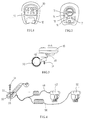
- a conventional, commercially available bicycle cycle computer comprises a main unit 10, and a display 20 for displaying data, such as the speed, the distance traveled, the time and the pedal rpm, is provided on the front surface of the main unit 10.
- a mode button 12 for selecting different displaying modes is provided below the display 20.
- Figure 2 shows the back of the main unit 10.
- reference numeral 13 denotes a battery cap for covering a battery accommodating chamber
- 14 denotes a set button for switching among different data setting modes
- 15 and 16 denote metal contacts for transmitting respective signals representing the detected speed and the detected pedal rpm (which will be described later) to a microprocessor (not shown) installed inside the main unit 10
- 17 denotes a metal contact as a common ground.
- the main unit 10 is preferably made to be detachable from the bicycle and portable.
- a conventional cycle computer is usually equipped with a bracket 30, as shown in Figure 3, which is mounted on a handlebar 90 of a bicycle by means of a screw 31.
- the main unit 10 can be inserted in the direction indicated by the arrow A as shown in Figure 3 so as to be detachably mounted onto the bracket 30.
- the rider can easily remove the main unit 10 from the bracket 30 whenever the bicycle is not in use, and mount the main unit 10 again later.
- Figure 4 shows the connection between the bracket 30 as shown in Figure 3 and two sensors 42 and 52 via cables 46 and 56.
- Figure 5 shows the position relationship between a magnet 44 mounted on one spoke 92 of the front wheel and the sensor 42 of Figure 4 mounted on the inside of the fork 94, facing the magnet 44, and
- Figure 6 shows the position relationship between a magnet 54 mounted on the inside of the crank 95 and the sensor 52 of Figure 4 mounted on the chain stay 96, facing the magnet 54.
- the signals are then transmitted to the microprocessor (not shown) in the main unit 10 through metal contacts 35 and 36 provided on the bracket 30 which are in electrical connection with the contacts 15 and 16 on the back of the main unit 10 when the main unit 10 is mounted on the bracket 30.
- the microprocessor performs, for example, identification, counting and calculation, on the supplied wheel rpm and pedal rpm data, and the processed data are then displayed on the display 20.
- the microprocessor of the main unit 10 calculates the speed by multiplying the wheel rpm with the circumferential length of the front wheel and calculates the distance traveled based on the calculated speed.
- the current pedal rpm or the average pedal rpm can be displayed to facilitate the rider's adjustment.
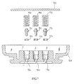
- Waterproof O-rings 15b, 16b and 17b are disposed in the holes 15a, 16a and 17a, respectively.
- Contact pins 15c, 16c and 17c are inserted to pass through the respective O-rings and protrude from the respective holes.
- Springs 15d, 16d and 17d for biasing the respective contact pins 15c, 16c and 17c outwards are provided between the pins and the printed circuit board 102. It is apparent that the waterproof arrangement for the contact is relatively complicated and the manufacturing cost therefore is high.
- a bicycle computer for a bicycle comprising: a first processing unit structured for mounting to the bicycle, a sensor or a plurality of sensors, each sensor providing sensor data to the first processing unit, wherein the first processing unit receives the sensor data from the sensor or the plurality of sensors and outputs serial format data corresponding to the sensor data, a main unit housing including a second processing unit and a display, whereby the second processing receives the serial format data from the first processing unit and outputs display data to the display of a personal computer.
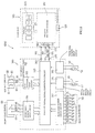
- FIG 8 is a block diagram showing a cycle computer.
- a cycle computer 1000 comprises a main unit 100 and a bracket 300.
- the main unit 100 is detachably mounted on the bracket 300 as described above in reference to Figure 3.
- the main unit 100 is provided with a primary microprocessor 110 and a display 200 for displaying various data processed by and supplied from the primary microprocessor 110.
- a mode button 120 for selecting different displaying modes is provided on the front surface of the main unit 100.
- Three metal contacts 170, 180 and 190 which are connected to the primary microprocessor 110 via signal transmission lines 171, 181 and 191, respectively, are provided on the back of the main unit 100.
- the contact 170 serves as a ground terminal, while the contact 180 is an input terminal for receiving a synchronous clock signal and the contact 190 is an input terminal for receiving a serial data signal (described in detail later).
- a waterproof arrangement as shown in Figure 7 is provided for each of the contacts 170, 180 and 190.
- the shape of the bracket 300 is substantially the same as that of the conventional bracket 30 as shown in Figures 3 and 4.
- a secondary microprocessor 310 is built in the bracket 300.
- Three metal contacts 370, 380 and 390 are provided on the surface of the bracket 300, and when the main unit 100 is mounted on the bracket 300, the contacts 170, 180 and 190 of the main unit 100 are brought into contact with the contacts 370, 380 and 390 of the bracket 300, respectively.
- the contacts 370, 380 and 390 are connected via signal transmission lines 371, 381 and 391 to three output terminals of a one-way parallel/serial signal converting circuit 320 (described in detail later) in the secondary microprocessor 310.
- the contact 370 serves as a ground terminal for the circuit 320.
- the contact 380 is used as a synchronous clock signal output terminal for the circuit 320 and the contact 390 is a serial data signal output terminal for the circuit 320.
- the secondary microprocessor 310 further comprises a wheel speed sensor input circuit 314, a pedal rpm sensor input circuit 315, a front gear sensor input circuit 316, a rear gear sensor input circuit 317, and a key buttons input circuit 318. Output signals from these circuits 314, 315, 316, 317 and 318 are transmitted to the one-way parallel/serial signal converting circuit 320.
- a wheel speed sensor 42 mounted as shown in Figure 5 is connected to the wheel speed sensor input circuit 314 via two signal transmission lines 46, and a pedal rpm sensor 52 mounted as shown in Figure 6 is connected to the pedal rpm sensor input circuit 315 via two signal transmission lines 56.
- a front gear sensor 60 mounted near one end of the bicycle handlebar is a three-position rotary switch which is connected to the front gear sensor input circuit 316 via three signal transmission lines 66, 67 and 68 and a ground wire 69.
- the front gear sensor 60 is coupled to a front gear shifting device (not shown) in order to detect the front gear in operation and supply the detected signal to the circuit 316.
- a rear gear sensor 70 mounted near the other end of the bicycle handlebar is a nine-position rotary switch which is connected to the rear gear sensor input circuit 317 via nine signal transmission lines 71 to 79 and a ground wire 79'.
- the rear gear sensor 70 is provided to detect the rear gear in operation and supply the detected signal to the circuit 317.
- a key buttons box 80 provided near one end of the handlebar has two remote key buttons 81 and 82.
- the first key button 81 is provided for selecting the displaying mode of the display 200 and the second key button 82 is a start/stop key button for starting or stopping a function of the main unit 100.
- the key buttons box 80 is connected to the key buttons input circuit 318 via two lines 83 and 84 and a ground wire 85.
- the contacts 170, 180 and 190 on the back of the main unit 100 are brought into contact with the contacts 370, 380 and 390 on the bracket 300, respectively, thereby making the primary microprocessor 110 in the main unit 100 and the secondary microprocessor 310 built in the bracket 300 electrically connected.
- a wheel speed signal detected by the wheel speed sensor 42 is transmitted to the wheel speed sensor input circuit 314 via lines 46 and then to the one-way parallel/serial signal converting circuit 320.
- a pedal rpm signal detected by the pedal rpm sensor 52 is supplied to the pedal rpm sensor input circuit 315 via lines 56 and then to the one-way parallel/serial signal converting circuit 320.
- a front gear shifting signal detected by the front gear sensor 60 coupled to the front gear shifting device is transmitted to the front gear sensor input circuit 316 and then to the converting circuit 320.
- a rear gear shifting signal detected by the rear gear sensor 70 coupled to the rear gear shifting device is transmitted to the rear gear sensor input circuit 317 and then to the converting circuit 320.
- a mode selecting signal is transmitted to the key buttons input circuit 318 and then to the converting circuit 320 if the key button 81 of the key buttons box 80 is pressed.
- a start/stop signal is outputted from the key buttons box 80 and transmitted to the key buttons input circuit 318 and then to the converting circuit 320.
- the one-way parallel/serial signal converting circuit 320 receives parallel input signals from the wheel speed sensor 42, the pedal rpm sensor 52, the front gear sensor 60, the rear gear sensor 70 and the key buttons box 80, and then converts the received parallel signals into a serial signal by means of parallel/serial signal conversion.
- the serial signal obtained after the conversion is transmitted from the secondary microprocessor 310 to the primary microprocessor 100 through the serial signal output terminal 390 of the former and the serial signal input terminal 190 of the later.
- the one-way parallel/serial signal converting circuit 320 generates a synchronous clock signal which is transmitted to the primary microprocessor 100 through the synchronous clock signal output terminal 380 and the synchronous clock signal input terminal 180.
- the signals transmitted from the converting circuit 320 of the secondary microprocessor 310 to the primary microprocessor 110 are shown in Figure 9.
- the serial signal comprises a set of data including, for example, BIT1 representing wheel speed data obtained from the wheel speed sensor 42, BIT2 representing pedal rpm data obtained from the pedal rpm sensor 52, BIT3 representing control data transmitted from the key buttons box 80, BIT4 representing front gear data obtained from the front gear sensor 60, BITS representing rear gear data obtained from the rear gear sensor 70, and so on.
- the primary microprocessor 110 performs identification, counting, calculation and other processes on the received data as shown in Figure 9, and displays the processed data requested by the rider on the display 200 of the main unit 100. Two or more kinds of data can be displayed on the display 200 simultaneously.
- the cycle computer comprises more sensors and hence provides more data when compared with the conventional cycle computer without increasing the number of contacts on the back of the main unit. Consequently, the construction of the main unit remains compact and simple.
- the rider can select the displaying mode without moving his hands away from the handlebar.
- a torque sensor is used to detect the torque exerted on the crank shaft and a microprocessor is used to determine whether the detected torque is higher than a predetermined value. If the detected torque is higher than the predetermined value, it indicates that the torque exerted on the crank shaft is too large, and hence a gearing-up is desired in order to reduce the load of the rider. Accordingly, a control signal for gearing-up is outputted from the microprocessor and transmitted to the electronic automatic gear shifting device for performing the gearing-up operation. On the other hand, if the detected torque is lower than the predetermined value, then a gearing-down is desired. Similarly, a control signal for gearing-down is transmitted from the microprocessor to the electronic automatic gear shifting device for performing the gearing-down operation.
- the aforementioned electronic automatic gear shifting device has been practically used, and the microprocessor in such a device can be integrated with the primary microprocessor in the main unit of the cycle computer according to the invention.
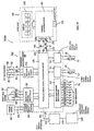
- FIG 10 is a block diagram showing such a cycle computer.
- the cycle computer 1000B comprises a torque sensor 150 for detecting the torque exerted on the crank shaft.
- the detected signal outputted from the torque sensor 150 is transmitted to a torque sensor input circuit 350 via lines 156, and then to a two-way parallel/serial signal converting circuit 330 in the secondary microprocessor 310 built in the bracket 300.
- the signal from the torque sensor 150 is converted together with signals from other sensors (42, 52, 60, 70) into a serial signal which is transmitted from the two-way parallel/serial signal converting circuit 330 to the primary microprocessor 110 in the main unit 100 through the serial signal output terminal 390.
- the primary microprocessor 110 determines whether the torque exerted on the crank shaft is higher or lower than a predetermined value based on the signal obtained from the torque sensor 150. If it is determined that the torque is higher than the predetermined value, then the torque exerted on the crank shaft is too large, and hence a gearing-up is desired. Accordingly, a control signal is outputted from the primary microprocessor 110 and transmitted to the secondary microprocessor 310 which then outputs a control signal OP for gearing-up to a gear shifting mechanism 450 of an electronic automatic gear shifting device 400 for performing the gearing-up operation through signal transmission lines 336 and 456. On the other hand, if the torque is lower than the predetermined value, it indicates that a gearing-down is desired. Therefore, the primary microprocessor 110 outputs a control signal for gearing-down which is then transmitted to the gear shifting mechanism 450 of the electronic automatic gear shifting device 400 for performing the gearing-down operation.
- control signals for gearing-up and gearing-down outputted from the primary microprocessor 110 are transmitted to the secondary microprocessor 310 via the existing lines 191 and 391 and the metal contacts 190 and 390.
- the cycle computer 1000B according to the invention can share the same microprocessor with an existing electronic automatic gear shifting device, thereby increasing the function of the cycle computer.
- sensors for detecting the physiological conditions of the rider and sensors for detecting the ambient conditions such as the temperature and the pressure are not incorporated therein, the addition of these sensors and other sensors becomes apparent for those skilled in the same field in the light of the teaching disclosed above.
Landscapes
- Physics & Mathematics (AREA)
- General Physics & Mathematics (AREA)
- Engineering & Computer Science (AREA)
- Mechanical Engineering (AREA)
- Arrangements For Transmission Of Measured Signals (AREA)
- Mechanical Control Devices (AREA)
- Traffic Control Systems (AREA)
Claims (9)
- Calculateur de bicyclette pour une bicyclette comprenant :où la première unité de traitement (310) reçoit les données de capteur du capteur ou de la pluralité de capteurs (42, 52, 60, 70) et fournit en sortie des données en format série correspondant aux données de capteur ;une première unité de traitement (310) structurée pour le montage sur la bicyclette, un capteur ou une pluralité de capteurs (42, 52, 60, 70, 80), chaque capteur fournissant des données de capteur à une première unité de traitement (310) ;
un boítier d'unité principale comprenant une seconde unité de traitement (110) et une unité d'affichage (200), de sorte que ;
la seconde unité de traitement (110) reçoit les données en format série de la première unité de traitement (310) et fournit des données d'affichage à l'unité d'affichage (200), caractérisé en ce que ;
chaque capteur ou la pluralité de capteurs (42, 52, 60, 70, 80) fournit des données de capteur en format parallèle à la première unité de traitement (310) ;
le boítier d'unité principale est montable de façon détachable sur la bicyclette ; et
l'unité principale (100) est raccordée par des lignes de transmission de signaux à la première unité de traitement ;
la première unité de traitement (310) et l'unité principale (100) ayant chacune des contacts pour le raccordement auxdites lignes de transmission ;
où la première unité de traitement (310) comprend une borne de sortie de commande (336) pour commander un mécanisme de changement de rapport de vitesse. - Calculateur de bicyclette selon la revendication 1, dans lequel la première unité de traitement (310) communique les données en format série à la seconde unité de traitement (110) via un premier contact prévu sur le boítier d'unité principale.
- Calculateur de bicyclette selon la revendication 1 ou 2, dans lequel seulement un premier contact unique communique les données en format série de la première unité de traitement (310) à la seconde unité de traitement (110).
- Calculateur de bicyclette selon l'une quelconque des revendications précédentes, dans lequel la seconde unité de traitement (110) communique des informations de contrôle pour fournir la commande de contrôle via le premier contact à la première unité de traitement (310).
- Calculateur de bicyclette selon l'une quelconque des revendications précédentes, dans lequel la première unité de traitement (310) génère un signal d'horloge synchrone qui est communiqué à la seconde unité de traitement (110) via un second contact placé sur le boítier d'unité principale.
- Calculateur de bicyclette selon la revendication 5, dans lequel seulement un second contact unique communique le signal d'horloge de la première unité de traitement (310) à la seconde unité de traitement (110).
- Calculateur de bicyclette selon l'une quelconque des revendications précédentes, dans lequel un troisième contact est prévu sur le boítier d'unité principale pour communiquer un signal de masse à partir de la première unité de traitement (310) à la seconde unité de traitement (110).
- Calculateur de bicyclette selon l'une quelconque des revendications précédentes, dans lequel la première unité de traitement (310) est disposée pour se raccorder à des capteurs qui comprennent un capteur de vitesse de roue et/ou un capteur de tours de pédale par minute et/ou un capteur de plateau de pédalier et/ou un capteur de pignon arrière et/ou au moins un capteur qui est fixé au corps du cycliste pour la détection de divers états physiologiques du cycliste.
- Calculateur de bicyclette pour bicyclette selon l'une quelconque des revendications précédentes, dans lequel exactement trois voies de communication communiquent des signaux de la première unité de traitement (310) à la seconde unité de traitement (110).
Applications Claiming Priority (2)
| Application Number | Priority Date | Filing Date | Title |
|---|---|---|---|
| US896309 | 1997-06-27 | ||
| US08/896,309 US6192300B1 (en) | 1997-06-27 | 1997-06-27 | Bicycle computer |
Publications (2)
| Publication Number | Publication Date |
|---|---|
| EP0887251A1 EP0887251A1 (fr) | 1998-12-30 |
| EP0887251B1 true EP0887251B1 (fr) | 2003-02-12 |
Family
ID=25405988
Family Applications (1)
| Application Number | Title | Priority Date | Filing Date |
|---|---|---|---|
| EP98111009A Expired - Lifetime EP0887251B1 (fr) | 1997-06-27 | 1998-06-16 | Calculateur de bicyclette |
Country Status (7)
| Country | Link |
|---|---|
| US (1) | US6192300B1 (fr) |
| EP (1) | EP0887251B1 (fr) |
| CN (1) | CN1086807C (fr) |
| CZ (1) | CZ297059B6 (fr) |
| DE (1) | DE69811295T2 (fr) |
| PL (1) | PL188812B1 (fr) |
| SK (1) | SK86698A3 (fr) |
Families Citing this family (55)
| Publication number | Priority date | Publication date | Assignee | Title |
|---|---|---|---|---|
| IT1310144B1 (it) * | 1999-08-24 | 2002-02-11 | Ferrero Spa | Sistema e procedimento per il controllo di trasmissioni a rapportovariabile |
| US6543799B2 (en) | 2000-01-13 | 2003-04-08 | Shimano Inc. | Bicycle suspension |
| IT1320286B1 (it) * | 2000-03-29 | 2003-11-26 | Campagnolo Srl | Sistema di controllo multiprocessore per cicli, ad esempio perbiciclette da competizione. |
| IT1320289B1 (it) * | 2000-03-29 | 2003-11-26 | Campagnolo Srl | Sistema per il trasferimento di dati, ad esempio per cicli qualibiciclette da competizione. |
| IT1320285B1 (it) | 2000-03-29 | 2003-11-26 | Campagnolo Srl | Procedimento per il controllo del cambio di velocita' in un ciclo,relativo sistema e relativi componenti. |
| US6836711B2 (en) | 2002-04-05 | 2004-12-28 | Michael Leonard Gentilcore | Bicycle data acquisition |
| US6741045B2 (en) | 2002-04-23 | 2004-05-25 | Shimano, Inc. | Bicycle control apparatus that communicates power and data over a single transmission path |
| US7015598B2 (en) * | 2002-04-23 | 2006-03-21 | Shimano, Inc. | Power control apparatus for a bicycle |
| US7116008B2 (en) * | 2002-04-23 | 2006-10-03 | Shimano, Inc. | Electrical communication system for a bicycle |
| JP3635306B2 (ja) * | 2002-06-11 | 2005-04-06 | 株式会社キャットアイ | ハンドルステムおよび速度表示装置 |
| US6724299B2 (en) * | 2002-06-27 | 2004-04-20 | Shimano, Inc. | Bicycle data communication method and apparatus |
| US6781510B2 (en) * | 2002-07-24 | 2004-08-24 | Shimano, Inc. | Bicycle computer control arrangement and method |
| JP2004110628A (ja) | 2002-09-20 | 2004-04-08 | Shimano Inc | 自転車ユーザの情報管理装置及びサイクルコンピュータ |
| US7006901B2 (en) * | 2002-11-18 | 2006-02-28 | Wang Everett X | Computerized automated dynamic control system for single-track vehicles |
| JP2004256047A (ja) * | 2003-02-27 | 2004-09-16 | Shimano Inc | 自転車用距離表示システム及び距離表示装置 |
| JP3717076B2 (ja) * | 2003-03-11 | 2005-11-16 | 株式会社シマノ | 二輪車用変速制御装置 |
| JP3777360B2 (ja) * | 2003-03-27 | 2006-05-24 | 株式会社シマノ | 自転車用情報処理装置 |
| JP3953990B2 (ja) * | 2003-08-22 | 2007-08-08 | 株式会社キャットアイ | 計測装置およびセンサ装置 |
| TWD104498S1 (zh) | 2003-08-25 | 2005-05-11 | 貓眼股份有限公司 | 自行車用速度表 |
| TWD104499S1 (zh) | 2003-08-25 | 2005-05-11 | 貓眼股份有限公司 | 自行車用速度計 |
| JP2005104258A (ja) * | 2003-09-30 | 2005-04-21 | Shimano Inc | 自転車用電装品ホルダー |
| US7612759B2 (en) * | 2004-05-12 | 2009-11-03 | Shimano Inc. | Cycle computer display apparatus |
| DE102004041832B3 (de) * | 2004-08-27 | 2005-12-08 | Cycle Parts Gmbh | Magnetischer Impulsgeber |
| US7740115B2 (en) * | 2004-11-24 | 2010-06-22 | Shimano Inc. | Bicycle sensor unit |
| DE102005039615B4 (de) * | 2005-08-19 | 2007-05-03 | Sigma-Elektro Gmbh | Vorrichtung zur Einstellung der Radgröße eines Fahrrades an einem Fahrradcomputer |
| USD528451S1 (en) * | 2005-09-16 | 2006-09-19 | Velocomp, Llp | Bicycle computer enclosure |
| ATE471274T1 (de) * | 2005-12-02 | 2010-07-15 | Campagnolo Srl | Kurbeleinheit für das tretlager, die antriebswelle und die tretpedalkurbel eines fahrrads |
| EP1820726B1 (fr) * | 2006-02-20 | 2011-09-14 | Campagnolo S.r.l. | Pédalier de bicyclette |
| DE602006019544D1 (de) * | 2006-03-03 | 2011-02-24 | Campagnolo Srl | Fahrradtretkurbellager-Anordnung und ein Adapter für eine derartige Anordnung |
| WO2007112571A1 (fr) * | 2006-03-31 | 2007-10-11 | 1531073 Ontario Inc. | Support sur tube de direction de bicyclette pour dispositifs périphériques électroniques |
| JP2007297040A (ja) | 2006-05-04 | 2007-11-15 | Campagnolo Spa | 自転車のクランクアーム・アセンブリ |
| ITMI20070140A1 (it) * | 2007-01-30 | 2008-07-31 | Campagnolo Srl | Dispositivo di interazione uomo-bicicletta |
| ITMI20070737A1 (it) * | 2007-04-12 | 2008-10-13 | Campagnolo Srl | Apparecchiatura e sistema elettronico per bicicletta e metodi relativi |
| US7878521B2 (en) * | 2007-04-16 | 2011-02-01 | Trek Bicycle Corporation | Bicycle frame with device cavity |
| US20090088934A1 (en) * | 2007-09-28 | 2009-04-02 | Shimano Inc. | Bicycle control system |
| US7902967B2 (en) * | 2007-10-23 | 2011-03-08 | Shimano Inc. | Bicycle control system |
| ITMI20070406U1 (it) * | 2007-12-05 | 2009-06-06 | Campagnolo Srl | Assieme di movimento centrale di bicicletta ed albero per un tale assieme |
| ITMI20072407A1 (it) * | 2007-12-20 | 2009-06-21 | Campagnolo Srl | Apparecchiatura elettronica per bicicletta |
| JP5046909B2 (ja) * | 2007-12-21 | 2012-10-10 | 株式会社日本マイクロニクス | 電気試験用接触子、これを用いる電気的接続装置、及び接触子の製造方法 |
| US20100010709A1 (en) * | 2008-01-24 | 2010-01-14 | Cannondale Bicycle Corporation | Bicycle distributed computing arrangement and method of operation |
| EP2757030B1 (fr) | 2008-01-24 | 2015-12-23 | Cycling Sports Group, Inc. | Système d'interface utilisateur de bicyclette et son procédé de fonctionnement |
| US8213794B2 (en) * | 2008-02-12 | 2012-07-03 | Nec Laboratories America, Inc. | Programmable optical network architecture |
| US7761212B2 (en) * | 2008-03-24 | 2010-07-20 | Shimano Inc. | Wireless communication apparatus |
| EP2110301B1 (fr) * | 2008-04-17 | 2014-12-24 | CAMPAGNOLO S.r.l. | Ensemble de composants de bicyclette rotatifs et bicyclette comportant un tel assemblage |
| US8643722B2 (en) * | 2008-10-08 | 2014-02-04 | Cerevellum Design, Llc | Rear-view display system for a bicycle |
| US20100123402A1 (en) * | 2008-11-19 | 2010-05-20 | Yi-Lun Chen | Bicycle control device |
| USD604187S1 (en) | 2009-02-13 | 2009-11-17 | Trek Bicycle Corporation | Electronic bicycle accessory |
| AR076221A1 (es) * | 2009-04-09 | 2011-05-26 | Astrazeneca Ab | Derivado de pirazol [4,5-e] pirimidina y su uso para tratar diabetes y obesidad |
| FI20095888A0 (fi) * | 2009-08-28 | 2009-08-28 | Polar Electro Oy | Pyöräilytietokone |
| US9702937B2 (en) * | 2015-02-17 | 2017-07-11 | Lg Chem, Ltd. | Contactor control system |
| CN105015664A (zh) * | 2015-07-30 | 2015-11-04 | 徐开友 | 触摸显示屏自行车码表及其制作方法 |
| CN105903154A (zh) * | 2016-05-16 | 2016-08-31 | 胡亚洲 | 一种主动式健身单车 |
| CN107438768B (zh) * | 2016-09-30 | 2020-05-19 | 深圳博芯科技股份有限公司 | 2.4GHz无线码表电路 |
| JP1619067S (fr) * | 2017-11-13 | 2018-11-26 | ||
| CN119935176A (zh) * | 2025-01-24 | 2025-05-06 | 成都晨电智能科技有限公司 | 一种低功耗骑行码表 |
Family Cites Families (26)
| Publication number | Priority date | Publication date | Assignee | Title |
|---|---|---|---|---|
| FR2308910A1 (fr) * | 1975-04-21 | 1976-11-19 | Genzling Claude | Dispositif compteur-tachymetre integre pour bicyclette |
| JPS58132807A (ja) * | 1982-01-30 | 1983-08-08 | Hino Motors Ltd | 自動車エンジン制御装置の制御デ−タ表示装置 |
| JPS5992812A (ja) | 1982-11-13 | 1984-05-29 | Masaki Date | プレス機械の材料送り装置 |
| JPS60118711U (ja) * | 1984-01-20 | 1985-08-10 | 株式会社キャットアイ | 自転車用走行データ表示装置 |
| DE3445617C2 (de) | 1984-07-13 | 1987-04-16 | Max Stegmann GmbH, Uhren- und Elektroapparatefabrik, 7710 Donaueschingen | Anordnung zur seriellen Übertragung der Meßwerte wenigstens eines Meßwertwandlers |
| JPS62237895A (ja) | 1986-04-09 | 1987-10-17 | Nippon Denso Co Ltd | 車載通信装置 |
| US4828257A (en) * | 1986-05-20 | 1989-05-09 | Powercise International Corporation | Electronically controlled exercise system |
| US5059158A (en) * | 1990-05-08 | 1991-10-22 | E.B.T., Inc. | Electronic transmission control system for a bicycle |
| JPH04104088A (ja) | 1990-08-23 | 1992-04-06 | Toshiba Corp | 原子炉停止装置 |
| US5177432A (en) * | 1991-05-31 | 1993-01-05 | Ppg Industries, Inc. | Wireless velocity detector for a bicycle having a rotating AC magnetic field and receiver coils |
| JPH0516041A (ja) | 1991-07-08 | 1993-01-26 | Sekisui Chem Co Ltd | 組立加工ラインにおける作業指示システム |
| DE4212319A1 (de) | 1992-04-13 | 1993-10-14 | Fichtel & Sachs Ag | Steuervorrichtung |
| DE4212320A1 (de) | 1992-04-13 | 1993-10-14 | Fichtel & Sachs Ag | Elektrische Stellvorrichtung |
| US5261858A (en) | 1992-06-19 | 1993-11-16 | Browning Automatic Transmission | Method and system for computer-controlled bicycle gear shifting |
| JPH0635573A (ja) | 1992-07-20 | 1994-02-10 | Citizen Watch Co Ltd | 電源回路装置 |
| JPH06203287A (ja) | 1992-12-30 | 1994-07-22 | Casio Comput Co Ltd | 無線式計測装置 |
| JPH06317601A (ja) | 1993-04-30 | 1994-11-15 | Sanyo Electric Co Ltd | 自転車用スピードメータ |
| JPH0717461A (ja) | 1993-06-30 | 1995-01-20 | Casio Comput Co Ltd | 最適運動量設定装置 |
| JP3475458B2 (ja) | 1993-09-28 | 2003-12-08 | カシオ計算機株式会社 | 走行状態検出装置および走行状態検出用受信機 |
| JPH07282905A (ja) | 1994-04-04 | 1995-10-27 | Casio Comput Co Ltd | 外部接続端子を備えた電子機器およびその接続構造 |
| JP2629609B2 (ja) | 1994-08-23 | 1997-07-09 | 株式会社デンソー | 制御システムのデータ出力方法 |
| JPH08133165A (ja) | 1994-11-09 | 1996-05-28 | Yamaha Motor Co Ltd | 電動自転車異常監視装置 |
| US5644511A (en) * | 1995-04-26 | 1997-07-01 | Mcwhorter; Gary T. | Cyclometer computer |
| DE29604853U1 (de) | 1996-03-15 | 1996-05-23 | Feurer, Peter, 90482 Nürnberg | Vorrichtung zur Aufzeichnung von Touren |
| US5737247A (en) * | 1996-04-04 | 1998-04-07 | Phil Orbanes Productions, Inc. | Bicycle accessory with voice synthesis capability |
| JP3088661B2 (ja) | 1996-07-23 | 2000-09-18 | 株式会社シマノ | 自転車における検出信号伝送方法および装置 |
-
1997
- 1997-06-27 US US08/896,309 patent/US6192300B1/en not_active Expired - Lifetime
-
1998
- 1998-06-16 EP EP98111009A patent/EP0887251B1/fr not_active Expired - Lifetime
- 1998-06-16 DE DE69811295T patent/DE69811295T2/de not_active Expired - Lifetime
- 1998-06-19 SK SK866-98A patent/SK86698A3/sk unknown
- 1998-06-24 CZ CZ0201598A patent/CZ297059B6/cs not_active IP Right Cessation
- 1998-06-25 PL PL98327025A patent/PL188812B1/pl not_active IP Right Cessation
- 1998-06-26 CN CN98115508A patent/CN1086807C/zh not_active Expired - Fee Related
Also Published As
| Publication number | Publication date |
|---|---|
| SK86698A3 (en) | 2000-02-14 |
| CZ297059B6 (cs) | 2006-08-16 |
| PL188812B1 (pl) | 2005-04-29 |
| DE69811295T2 (de) | 2003-09-11 |
| CN1212361A (zh) | 1999-03-31 |
| US6192300B1 (en) | 2001-02-20 |
| CZ9802015A3 (cs) | 1999-01-13 |
| CN1086807C (zh) | 2002-06-26 |
| DE69811295D1 (de) | 2003-03-20 |
| PL327025A1 (en) | 1999-01-04 |
| EP0887251A1 (fr) | 1998-12-30 |
Similar Documents
| Publication | Publication Date | Title |
|---|---|---|
| EP0887251B1 (fr) | Calculateur de bicyclette | |
| TWI824985B (zh) | 用於電動輔助自行車之介面 | |
| TW472011B (en) | Bicycle display unit with backlight | |
| CN101417689B (zh) | 自行车控制系统 | |
| US20060208453A1 (en) | Apparatus for mounting an electrical component to a bicycle | |
| EP1693292B1 (fr) | Unité de commande d'une bicyclette | |
| EP0125842B1 (fr) | Dispositif d'affichage à mémoire d'informations, par exemple une montre-bracelet | |
| EP1357678B1 (fr) | Calculateur de bicyclette qui transmet la puissance et les données sur un seul fil | |
| JP3231018B2 (ja) | 自転車用コンピュータ | |
| JP2025027104A5 (fr) | ||
| US7253610B2 (en) | Self-powered bicycle signal output device and display apparatus using same | |
| TW201836912A (zh) | 自行車用驅動系統、自行車用驅動單元及自行車用電池單元 | |
| US20060186158A1 (en) | Water resisting apparatus for a bicycle electrical component | |
| RU2253896C2 (ru) | Цикловой велокомпьютер (варианты) | |
| US20070270719A1 (en) | Automatic speed setting system for bicycle use | |
| CN217496432U (zh) | 电动滑板车控制系统 | |
| NZ333459A (en) | Electronic module for conventional parking meter | |
| GB2439090A (en) | Bicycle with automatic speed setting in response to physiological parameters | |
| CN215682297U (zh) | 一种无线图传对频装置 | |
| EP1594723A2 (fr) | Module de commutateur multiple | |
| CN222483161U (zh) | 一种带有计数插座及时钟计时和可调节定时功能的脚踏板式开关 | |
| CN216388434U (zh) | 驾驶模拟器及在环硬件试验系统 | |
| CN115123436A (zh) | 电动滑板车控制系统 | |
| TH3864A3 (th) | เครื่องอ่านแปลสัญญาณรหัสปัญหาของระบบรถยนต์ | |
| TW202200441A (zh) | 一種使用滑環套件,can bus(控制器區域網路)以及智能曲柄組成之電動腳踏車(船)系統 |
Legal Events
| Date | Code | Title | Description |
|---|---|---|---|
| PUAI | Public reference made under article 153(3) epc to a published international application that has entered the european phase |
Free format text: ORIGINAL CODE: 0009012 |
|
| AK | Designated contracting states |
Kind code of ref document: A1 Designated state(s): DE FR IT |
|
| AX | Request for extension of the european patent |
Free format text: AL;LT;LV;MK;RO;SI |
|
| 17P | Request for examination filed |
Effective date: 19990125 |
|
| AKX | Designation fees paid |
Free format text: DE FR IT |
|
| 17Q | First examination report despatched |
Effective date: 19990927 |
|
| GRAH | Despatch of communication of intention to grant a patent |
Free format text: ORIGINAL CODE: EPIDOS IGRA |
|
| GRAH | Despatch of communication of intention to grant a patent |
Free format text: ORIGINAL CODE: EPIDOS IGRA |
|
| GRAA | (expected) grant |
Free format text: ORIGINAL CODE: 0009210 |
|
| AK | Designated contracting states |
Designated state(s): DE FR IT |
|
| REF | Corresponds to: |
Ref document number: 69811295 Country of ref document: DE Date of ref document: 20030320 Kind code of ref document: P |
|
| RAP2 | Party data changed (patent owner data changed or rights of a patent transferred) |
Owner name: ECHOWELL ELECTRONIC CO. LTD. Owner name: SHIMANO INC. |
|
| ET | Fr: translation filed | ||
| PLBE | No opposition filed within time limit |
Free format text: ORIGINAL CODE: 0009261 |
|
| STAA | Information on the status of an ep patent application or granted ep patent |
Free format text: STATUS: NO OPPOSITION FILED WITHIN TIME LIMIT |
|
| 26N | No opposition filed |
Effective date: 20031113 |
|
| PGFP | Annual fee paid to national office [announced via postgrant information from national office to epo] |
Ref country code: IT Payment date: 20130620 Year of fee payment: 16 Ref country code: FR Payment date: 20130624 Year of fee payment: 16 |
|
| REG | Reference to a national code |
Ref country code: FR Ref legal event code: ST Effective date: 20150227 |
|
| PG25 | Lapsed in a contracting state [announced via postgrant information from national office to epo] |
Ref country code: IT Free format text: LAPSE BECAUSE OF NON-PAYMENT OF DUE FEES Effective date: 20140616 |
|
| PG25 | Lapsed in a contracting state [announced via postgrant information from national office to epo] |
Ref country code: FR Free format text: LAPSE BECAUSE OF NON-PAYMENT OF DUE FEES Effective date: 20140630 |
|
| PGFP | Annual fee paid to national office [announced via postgrant information from national office to epo] |
Ref country code: DE Payment date: 20150609 Year of fee payment: 18 |
|
| REG | Reference to a national code |
Ref country code: DE Ref legal event code: R119 Ref document number: 69811295 Country of ref document: DE |
|
| PG25 | Lapsed in a contracting state [announced via postgrant information from national office to epo] |
Ref country code: DE Free format text: LAPSE BECAUSE OF NON-PAYMENT OF DUE FEES Effective date: 20170103 |