EP0887535B1 - Drosselklappenkontrolleinrichtung für einen Verbrennungsmotor - Google Patents
Drosselklappenkontrolleinrichtung für einen Verbrennungsmotor Download PDFInfo
- Publication number
- EP0887535B1 EP0887535B1 EP98111453A EP98111453A EP0887535B1 EP 0887535 B1 EP0887535 B1 EP 0887535B1 EP 98111453 A EP98111453 A EP 98111453A EP 98111453 A EP98111453 A EP 98111453A EP 0887535 B1 EP0887535 B1 EP 0887535B1
- Authority
- EP
- European Patent Office
- Prior art keywords
- engine
- torque
- target
- parameter
- air flow
- Prior art date
- Legal status (The legal status is an assumption and is not a legal conclusion. Google has not performed a legal analysis and makes no representation as to the accuracy of the status listed.)
- Expired - Lifetime
Links
- 239000000446 fuel Substances 0.000 claims description 65
- 238000010586 diagram Methods 0.000 description 14
- 238000002485 combustion reaction Methods 0.000 description 12
- 238000012937 correction Methods 0.000 description 10
- 239000007789 gas Substances 0.000 description 7
- 238000002347 injection Methods 0.000 description 6
- 239000007924 injection Substances 0.000 description 6
- 238000006243 chemical reaction Methods 0.000 description 5
- 230000006870 function Effects 0.000 description 5
- 238000000034 method Methods 0.000 description 3
- 230000006835 compression Effects 0.000 description 2
- 238000007906 compression Methods 0.000 description 2
- 239000002826 coolant Substances 0.000 description 2
- 239000000203 mixture Substances 0.000 description 2
- 230000001133 acceleration Effects 0.000 description 1
- 230000003197 catalytic effect Effects 0.000 description 1
- 239000000498 cooling water Substances 0.000 description 1
- 230000000994 depressogenic effect Effects 0.000 description 1
- 238000009499 grossing Methods 0.000 description 1
- 239000008240 homogeneous mixture Substances 0.000 description 1
- 238000012986 modification Methods 0.000 description 1
- 230000004048 modification Effects 0.000 description 1
- 238000011144 upstream manufacturing Methods 0.000 description 1
Images






Classifications
-
- F—MECHANICAL ENGINEERING; LIGHTING; HEATING; WEAPONS; BLASTING
- F02—COMBUSTION ENGINES; HOT-GAS OR COMBUSTION-PRODUCT ENGINE PLANTS
- F02D—CONTROLLING COMBUSTION ENGINES
- F02D41/00—Electrical control of supply of combustible mixture or its constituents
- F02D41/02—Circuit arrangements for generating control signals
- F02D41/14—Introducing closed-loop corrections
-
- F—MECHANICAL ENGINEERING; LIGHTING; HEATING; WEAPONS; BLASTING
- F02—COMBUSTION ENGINES; HOT-GAS OR COMBUSTION-PRODUCT ENGINE PLANTS
- F02D—CONTROLLING COMBUSTION ENGINES
- F02D11/00—Arrangements for, or adaptations to, non-automatic engine control initiation means, e.g. operator initiated
- F02D11/06—Arrangements for, or adaptations to, non-automatic engine control initiation means, e.g. operator initiated characterised by non-mechanical control linkages, e.g. fluid control linkages or by control linkages with power drive or assistance
- F02D11/10—Arrangements for, or adaptations to, non-automatic engine control initiation means, e.g. operator initiated characterised by non-mechanical control linkages, e.g. fluid control linkages or by control linkages with power drive or assistance of the electric type
- F02D11/105—Arrangements for, or adaptations to, non-automatic engine control initiation means, e.g. operator initiated characterised by non-mechanical control linkages, e.g. fluid control linkages or by control linkages with power drive or assistance of the electric type characterised by the function converting demand to actuation, e.g. a map indicating relations between an accelerator pedal position and throttle valve opening or target engine torque
-
- F—MECHANICAL ENGINEERING; LIGHTING; HEATING; WEAPONS; BLASTING
- F02—COMBUSTION ENGINES; HOT-GAS OR COMBUSTION-PRODUCT ENGINE PLANTS
- F02D—CONTROLLING COMBUSTION ENGINES
- F02D31/00—Use of speed-sensing governors to control combustion engines, not otherwise provided for
- F02D31/001—Electric control of rotation speed
- F02D31/002—Electric control of rotation speed controlling air supply
- F02D31/003—Electric control of rotation speed controlling air supply for idle speed control
-
- F—MECHANICAL ENGINEERING; LIGHTING; HEATING; WEAPONS; BLASTING
- F02—COMBUSTION ENGINES; HOT-GAS OR COMBUSTION-PRODUCT ENGINE PLANTS
- F02D—CONTROLLING COMBUSTION ENGINES
- F02D35/00—Controlling engines, dependent on conditions exterior or interior to engines, not otherwise provided for
- F02D35/0015—Controlling engines, dependent on conditions exterior or interior to engines, not otherwise provided for using exhaust gas sensors
- F02D35/0023—Controlling air supply
-
- F—MECHANICAL ENGINEERING; LIGHTING; HEATING; WEAPONS; BLASTING
- F02—COMBUSTION ENGINES; HOT-GAS OR COMBUSTION-PRODUCT ENGINE PLANTS
- F02D—CONTROLLING COMBUSTION ENGINES
- F02D41/00—Electrical control of supply of combustible mixture or its constituents
- F02D41/0002—Controlling intake air
-
- F—MECHANICAL ENGINEERING; LIGHTING; HEATING; WEAPONS; BLASTING
- F02—COMBUSTION ENGINES; HOT-GAS OR COMBUSTION-PRODUCT ENGINE PLANTS
- F02D—CONTROLLING COMBUSTION ENGINES
- F02D41/00—Electrical control of supply of combustible mixture or its constituents
- F02D41/0002—Controlling intake air
- F02D41/0005—Controlling intake air during deceleration
-
- F—MECHANICAL ENGINEERING; LIGHTING; HEATING; WEAPONS; BLASTING
- F02—COMBUSTION ENGINES; HOT-GAS OR COMBUSTION-PRODUCT ENGINE PLANTS
- F02D—CONTROLLING COMBUSTION ENGINES
- F02D11/00—Arrangements for, or adaptations to, non-automatic engine control initiation means, e.g. operator initiated
- F02D11/06—Arrangements for, or adaptations to, non-automatic engine control initiation means, e.g. operator initiated characterised by non-mechanical control linkages, e.g. fluid control linkages or by control linkages with power drive or assistance
- F02D11/10—Arrangements for, or adaptations to, non-automatic engine control initiation means, e.g. operator initiated characterised by non-mechanical control linkages, e.g. fluid control linkages or by control linkages with power drive or assistance of the electric type
- F02D2011/101—Arrangements for, or adaptations to, non-automatic engine control initiation means, e.g. operator initiated characterised by non-mechanical control linkages, e.g. fluid control linkages or by control linkages with power drive or assistance of the electric type characterised by the means for actuating the throttles
-
- F—MECHANICAL ENGINEERING; LIGHTING; HEATING; WEAPONS; BLASTING
- F02—COMBUSTION ENGINES; HOT-GAS OR COMBUSTION-PRODUCT ENGINE PLANTS
- F02D—CONTROLLING COMBUSTION ENGINES
- F02D11/00—Arrangements for, or adaptations to, non-automatic engine control initiation means, e.g. operator initiated
- F02D11/06—Arrangements for, or adaptations to, non-automatic engine control initiation means, e.g. operator initiated characterised by non-mechanical control linkages, e.g. fluid control linkages or by control linkages with power drive or assistance
- F02D11/10—Arrangements for, or adaptations to, non-automatic engine control initiation means, e.g. operator initiated characterised by non-mechanical control linkages, e.g. fluid control linkages or by control linkages with power drive or assistance of the electric type
- F02D2011/101—Arrangements for, or adaptations to, non-automatic engine control initiation means, e.g. operator initiated characterised by non-mechanical control linkages, e.g. fluid control linkages or by control linkages with power drive or assistance of the electric type characterised by the means for actuating the throttles
- F02D2011/102—Arrangements for, or adaptations to, non-automatic engine control initiation means, e.g. operator initiated characterised by non-mechanical control linkages, e.g. fluid control linkages or by control linkages with power drive or assistance of the electric type characterised by the means for actuating the throttles at least one throttle being moved only by an electric actuator
-
- F—MECHANICAL ENGINEERING; LIGHTING; HEATING; WEAPONS; BLASTING
- F02—COMBUSTION ENGINES; HOT-GAS OR COMBUSTION-PRODUCT ENGINE PLANTS
- F02D—CONTROLLING COMBUSTION ENGINES
- F02D2200/00—Input parameters for engine control
- F02D2200/02—Input parameters for engine control the parameters being related to the engine
- F02D2200/04—Engine intake system parameters
- F02D2200/0402—Engine intake system parameters the parameter being determined by using a model of the engine intake or its components
-
- F—MECHANICAL ENGINEERING; LIGHTING; HEATING; WEAPONS; BLASTING
- F02—COMBUSTION ENGINES; HOT-GAS OR COMBUSTION-PRODUCT ENGINE PLANTS
- F02D—CONTROLLING COMBUSTION ENGINES
- F02D2200/00—Input parameters for engine control
- F02D2200/02—Input parameters for engine control the parameters being related to the engine
- F02D2200/04—Engine intake system parameters
- F02D2200/0406—Intake manifold pressure
-
- F—MECHANICAL ENGINEERING; LIGHTING; HEATING; WEAPONS; BLASTING
- F02—COMBUSTION ENGINES; HOT-GAS OR COMBUSTION-PRODUCT ENGINE PLANTS
- F02D—CONTROLLING COMBUSTION ENGINES
- F02D2200/00—Input parameters for engine control
- F02D2200/02—Input parameters for engine control the parameters being related to the engine
- F02D2200/10—Parameters related to the engine output, e.g. engine torque or engine speed
- F02D2200/1002—Output torque
- F02D2200/1004—Estimation of the output torque
-
- F—MECHANICAL ENGINEERING; LIGHTING; HEATING; WEAPONS; BLASTING
- F02—COMBUSTION ENGINES; HOT-GAS OR COMBUSTION-PRODUCT ENGINE PLANTS
- F02D—CONTROLLING COMBUSTION ENGINES
- F02D2250/00—Engine control related to specific problems or objectives
- F02D2250/18—Control of the engine output torque
-
- F—MECHANICAL ENGINEERING; LIGHTING; HEATING; WEAPONS; BLASTING
- F02—COMBUSTION ENGINES; HOT-GAS OR COMBUSTION-PRODUCT ENGINE PLANTS
- F02D—CONTROLLING COMBUSTION ENGINES
- F02D2250/00—Engine control related to specific problems or objectives
- F02D2250/41—Control to generate negative pressure in the intake manifold, e.g. for fuel vapor purging or brake booster
-
- F—MECHANICAL ENGINEERING; LIGHTING; HEATING; WEAPONS; BLASTING
- F02—COMBUSTION ENGINES; HOT-GAS OR COMBUSTION-PRODUCT ENGINE PLANTS
- F02D—CONTROLLING COMBUSTION ENGINES
- F02D35/00—Controlling engines, dependent on conditions exterior or interior to engines, not otherwise provided for
- F02D35/02—Controlling engines, dependent on conditions exterior or interior to engines, not otherwise provided for on interior conditions
- F02D35/023—Controlling engines, dependent on conditions exterior or interior to engines, not otherwise provided for on interior conditions by determining the cylinder pressure
-
- F—MECHANICAL ENGINEERING; LIGHTING; HEATING; WEAPONS; BLASTING
- F02—COMBUSTION ENGINES; HOT-GAS OR COMBUSTION-PRODUCT ENGINE PLANTS
- F02D—CONTROLLING COMBUSTION ENGINES
- F02D41/00—Electrical control of supply of combustible mixture or its constituents
- F02D41/30—Controlling fuel injection
- F02D41/3011—Controlling fuel injection according to or using specific or several modes of combustion
- F02D41/3017—Controlling fuel injection according to or using specific or several modes of combustion characterised by the mode(s) being used
- F02D41/3023—Controlling fuel injection according to or using specific or several modes of combustion characterised by the mode(s) being used a mode being the stratified charge spark-ignited mode
- F02D41/3029—Controlling fuel injection according to or using specific or several modes of combustion characterised by the mode(s) being used a mode being the stratified charge spark-ignited mode further comprising a homogeneous charge spark-ignited mode
-
- Y—GENERAL TAGGING OF NEW TECHNOLOGICAL DEVELOPMENTS; GENERAL TAGGING OF CROSS-SECTIONAL TECHNOLOGIES SPANNING OVER SEVERAL SECTIONS OF THE IPC; TECHNICAL SUBJECTS COVERED BY FORMER USPC CROSS-REFERENCE ART COLLECTIONS [XRACs] AND DIGESTS
- Y02—TECHNOLOGIES OR APPLICATIONS FOR MITIGATION OR ADAPTATION AGAINST CLIMATE CHANGE
- Y02T—CLIMATE CHANGE MITIGATION TECHNOLOGIES RELATED TO TRANSPORTATION
- Y02T10/00—Road transport of goods or passengers
- Y02T10/10—Internal combustion engine [ICE] based vehicles
- Y02T10/40—Engine management systems
Definitions
- This invention is directed to an engine throttle control apparatus for a vehicle.
- Some vehicles have a boost control valve function (that is, a negative pressure control function during deceleration) in addition to such an idling speed control function.
- the boost control valve function entails introducing air into the intake manifold to prevent excessive intake manifold vacuum during deceleration when the throttle valve is being closed. This is effective to limit the vacuum (or negative pressure) in the cylinder so as to reduce oil leakage into the cylinder and minimize other problems.
- the degree of opening of the auxiliary air control valve is set as follows.
- a controlled variable BCV is stored in a table according to the engine speed. Control is made with reference to this table during deceleration.
- a comparison is made between a controlled variable ISC (used for idling speed control) and the controlled variable BCV (for negative pressure control). A greater one of these controlled variables is selected to control the air intake. Further details regarding such control techniques are set forth in U.S. Patent No. 4,951,209 and Japanese Patent Kokai Nos. 1-121536 and 1-294933.
- torque demand control has been suggested to control a throttle valve in an electronic manner (U.S. application serial No. 08/804,454, filed February 21, 1997, which disclosure is incorporated by reference into this application).
- Such torque demand control entails calculating a target engine torque based on accelerator position and other parameters (for example, accelerator position and engine speed), and calculating a basic fuel delivery requirement value in a manner so as to realize the target engine torque.
- a target intake air flow rate is calculated based on the basic fuel delivery requirement value and a target air-fuel ratio.
- a target throttle valve position is calculated based on the target intake air flow rate, and the throttle valve is controlled to the target throttle valve position.
- negative pressure control can be realized by calculating a negative pressure control target intake air flow rate for negative pressure control during deceleration, after the target intake air flow rate is calculated for torque demand control, and by selecting a greater one of the negative pressure control target intake air flow rate and the target intake air flow rate based on torque demand, and calculating the target throttle position based on the selected rate.
- the vehicle does not act in accordance with the driver's demand and expectations.
- the time between t1 and t2 can be up to several seconds.
- an object of the invention is to improve driving performance by combining driver and engine demands in such a manner that a change demanded by a driver is reflected in overall engine output.
- the invention is an engine throttle valve controller for a vehicle having an engine with a throttle valve.
- the controller includes a driver's demand torque calculation section to calculate a driver's demand torque that corresponds to a driver's request based on at least accelerator position.
- An engine demand torque calculation section calculates a first parameter representing a torque that the engine requires irrespective of the driver's accelerator request (for example, a torque required to maintain a minimum idle speed).
- a minimum air flow calculation section calculates a second parameter representing a minimum air flow into the engine.
- a selection section selects a greater one of the first parameter and the second parameter.
- a combination section combines the driver's demand torque with a torque corresponding to the parameter selected by the selection section to produce a target torque to control the throttle valve.
- the second parameter can represent a minimum air flow into the engine for boost control.
- the first parameter and the second parameter can be, for example, torques or air flow rates.
- the minimum air flow calculation section can calculate the second parameter based at least in part on a variable target air-fuel ratio.
- the engine demand torque calculation section can calculate the first parameter such that engine idle speed is maintained during engine idle control.
- Fig. 2 is a system diagram showing a direct-injection spark-ignition engine 1 to which the invention is applicable.
- Air is introduced through an air cleaner 2 into an intake passage 3.
- An electronic controlled throttle valve 4 controls the amount of air provided to the engine.
- the degree of opening of the electronic controlled throttle valve 4 (the throttle valve position) is controlled by, for example, a step motor operated in response to a signal from a control unit 20.
- An electro-magnetic fuel injector 5 is provided for direct injection of fuel (gasoline) into the combustion chamber.
- the fuel injector 5 opens to inject fuel, adjusted to a predetermined pressure, when its solenoid receives a fuel injection pulse signal outputted from the control unit 20 during an intake or compression stroke in synchronism with engine rotation to inject fuel.
- the injected fuel diffuses in the combustion chamber to form a homogeneous mixture.
- a stratified mixture is formed around a spark plug 6.
- the spark plug 6 produces a spark to ignite the mixture for combustion.
- the combustion modes can include homogeneous stoichiometric combustion (at an air-fuel ratio of about 14.7), homogeneous lean combustion (at air-fuel ratios ranging from about 20 to 30), and stratified lean combustion (at air-fuel ratios of about 40), in accordance with air-fuel ratio control (to be discussed below).
- Exhaust gases are discharged from the engine 1 into an exhaust passage 7.
- the exhaust passage 7 has a catalytic converter 8 for purifying the exhaust gases.
- the control unit, or controller, 20 includes a microcomputer or other processor comprised of a CPU, a ROM, a RAM, an A/D converter and an input/output interface and receives signals from various sensors.
- a microcomputer or other processor comprised of a CPU, a ROM, a RAM, an A/D converter and an input/output interface and receives signals from various sensors.
- One suitable control unit is, for example, a Hitachi SH70 series processor, programmed in C and/or machine language.
- crankshaft and camshaft angle sensors 21 and 22 for detecting the rotation of the crankshaft and/or camshaft of the engine 1.
- the sensors 21 and 22 produce a reference pulse signal REF for each 720°/n of shaft rotation (where n is the number of cylinders) at a predetermined shaft position and also a unit pulse signal POS at a predetermined number of degrees (1 or 2) of rotation of the shaft.
- the engine speed Ne can be calculated based on the period of the reference pulse signal REF.
- the sensors also include an airflow meter 23 provided in the intake passage 3 at a position upstream of the throttle valve 4 for detecting the intake air flow rate Qa (the amount of air permitted to enter the engine); an accelerator position sensor 24 for detecting the accelerator position ACC (the degree to which the accelerator is depressed); and a throttle valve sensor 25 (including an idle switch positioned to be turned on when the throttle valve 4 is fully closed to a predetermined position, which will be taken in response to the accelerator being fully released) for detecting the degree TVO of opening of the throttle valve 4. It should be noted that the throttle valve 4 will not be fully closed so that air may be introduced to the engine without providing an auxiliary air passage across the throttle valve 4.
- the throttle valve sensor 25 may be omitted as long as the accelerator position sensor 24 produces a replacement signal upon release of the accelerator pedal.
- the sensors further include a coolant temperature sensor 26 for detecting the temperature Tw of the coolant of the engine 1; an O 2 sensor 27 positioned in the exhaust passage 7 for producing a signal corresponding to the rich/lean condition of the exhaust gas (air-fuel ratio); and a vehicle speed sensor 28 for detecting the vehicle speed VSP.
- the control unit 20 receives the signals fed thereto from the various sensors and, using a microcomputer built therein, makes the calculations for torque demand control, as shown in the control block diagrams of Figs. 3 and 4, to control the degree of opening of the electronic controlled throttle valve 4 and the fuel injector 5 in a manner to control the amount of fuel injected into the engine.
- Fig. 3 is a control block diagram showing overall torque demand control.
- Fig. 4 is a control block diagram showing a portion of throttle valve position control of the torque demand control and details of the target torque calculation section.
- the sections described herein are implemented in hardware, software, or a combination of both, in the control unit 20, in accordance with the descriptions set forth herein.
- this first embodiment includes a target torque calculation section 100.
- Target torque calculation section 100 includes a driver's demand torque calculation section 101, an ISC (idle speed control) target torque calculation section 103, a negative pressure control target intake (air) flow rate calculation section 105, a torque conversion section 106, a correction section 107, a selection section 108, and an addition section 109.
- Section 101 calculates a first target torque, which corresponds to the torque required by the driver, using a map such as the one shown in Fig. 5, which indicates how target torque varies in accordance with accelerator operation quantity (typically, accelerator depression) and measured engine speed.
- accelerator operation quantity typically, accelerator depression
- Section 103 calculates a second target torque which corresponds to the torque required to control the engine speed to a predetermined value during idle control using a map, such as the one shown in Fig. 6, which indicates how target torque for idle control varies with engine cooling water temperature.
- a map such as the one shown in Fig. 6, which indicates how target torque for idle control varies with engine cooling water temperature.
- target torque for idle control can be reduced because the engine is operating in a more stable condition.
- the value obtained from a curve such as the one shown in Fig. 6 can be further modified by taking into account various other parameters, such as whether or not the air conditioner is in operation. For example, if the air conditioner is in operation, the target torque can be increased by, for example, 5 N.m.
- Section 105 calculates the air flow rate necessary to ensure that the boost developed within the intake passage during deceleration is at a predetermined level (such as -600mmHg). This minimizes oil leakage into the cylinder.
- a target lower limit negative pressure (for example -600mmHg) is set.
- a negative pressure control target intake air flow rate corresponding to the target lower limit negative pressure is calculated. This calculation can be made based on the following formula: cylinder volume x (760 - 600)/760 The calculation can be refined to take into account residual gases in the cylinder, such as internal EGR gas.
- Torque conversion section 106 generates a torque based on the air flow rate from section 105 and an air-fuel ratio received from a target air-fuel ratio calculation section 113 (section 113 will be described below).
- the torque is obtained by dividing the air flow rate by the air-fuel ratio and then multiplying the quotient by a coefficient K1.
- the selection section 108 makes a comparison between the ISC target torque from section 103 and the negative pressure control target torque from section 106 (corresponding to the negative pressure control target intake air flow rate), selects the greater one, and outputs the selected torque.
- the adding section 109 adds the torque from section 108 to the driver's demand torque from section 101 to calculate a target torque. These two torques can be combined in a manner other than straight addition.
- a basic fuel delivery requirement calculation section 111 a required basic fuel quantity is calculated. This basic fuel quantity is proportional to the target torque generated by section 109, and is obtained by, for example, multiplying the target torque from section 109 by a coefficient K2.
- Efficiency correction section 112 corrects for combustion efficiency, which varies when air-fuel ratio changes between homogeneous combustion (low air-fuel ratios) and stratified combustion (high air-fuel ratios).
- a map such as the one shown in Fig. 7 is used to obtain an efficiency corresponding to the air-fuel ratio.
- the output of section 111 is divided by the efficiency value obtained from Fig. 7.
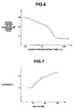
- 'Target air-fuel ratio calculation section 113 uses a map such as the one shown in Fig. 8 to set the target air-fuel ratio (tAFR) based on actual engine speed. Specifically, tAFR is obtained from Fig. 8 as corresponding to actual engine speed by presuming the magnitude of target torque to be substantially minimal. This is because the amount of torque during deceleration for the boost control may be minimal as long as a minimum air flow into the engine is maintained. Additional discussion regarding how target air-fuel ratio can be adjusted for various engine operating conditions is set forth in U.S. Patent Application No. 08/901,963, filed July 29, 1997 and entitled "Control System for Internal Combustion Engine.”
- a target intake air flow rate calculation section 114 includes a multiplier which multiplies the corrected basic fuel delivery requirement from section 112 by the target air-fuel ratio from section 113 to calculate a target intake air flow rate per cylinder (tQcy1).
- a target throttle position calculation section 115 calculates a target throttle opening by first obtaining the target intake air quantity (flow) for all of the cylinders by multiplying the target intake air flow rate per cylinder (from section 114) by engine speed and a coefficient K3. Then, using a map such as the one shown in Fig. 9, the target throttle opening degree is determined, based on the target intake air quantity and engine speed.
- a throttle valve drive control section 116 drives a DC motor (or a step motor in a stepped manner) in response to a command signal corresponding to the target throttle opening degree so as to bring the throttle valve 4 to the target throttle opening degree.
- the airflow meter 23 detects the actual intake air flow rate (Qa), controlled by the throttle valve 4.
- cylinder intake air flow rate calculation section 117 calculates a cylinder intake air flow rate (Qcyl) by dividing the actual intake air flow rate Qa by the engine speed Ne, or by smoothing the actual intake air flow rate.
- a target fuel supply calculation section 118 includes a divider for dividing the cylinder intake air flow rate (Qcyl) by the target air-fuel ratio (tAFR) to calculate a target fuel supply (tQfi).
- a fuel supply calculation section 119 makes various corrections to the target fuel supply (tQfi).
- a fuel injector drive control section 120 produces a drive pulse signal having a pulse width corresponding to the corrected target fuel supply to drive the fuel injector 5 such that fuel injector 5 is controlled to realize the corrected target fuel supply.
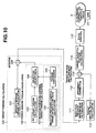
- Figs. 10 and 11 show second and third embodiments.
- the Fig. 10 embodiment is similar to the Fig. 4 embodiment except that in the Fig. 10 embodiment, the negative pressure control target intake flow rate is not corrected using the target air-fuel ratio.
- Fig. 10 illustrates that the target torque calculation is separated into a driver's demand torque calculation (performed by section 101) and engine demand torque calculation (performed by an engine demand torque calculation section 102). The other embodiments can also be divided into driver demand and engine demand sections.
- the Fig. 11 embodiment is similar to the Fig. 4 embodiment except that in the Fig. 11 embodiment, correction for the target air-fuel ratio during the negative pressure control calculations is performed in a correction section 107' after conversion of the negative pressure control target intake air flow rate to a torque value. This is done by dividing the torque from section 106 by the target air-fuel ratio from section 113.
- Such corrections for target air-fuel ratio permit application of the invention to engines such as direct-injection spark-ignition type engines and the like wherein the air-fuel ratio changes over great range, by making a correction based on the target air-fuel ratio upon, for example, torque conversion of the negative pressure control target intake air flow rate.
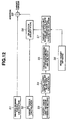
- Figs. 12 and 13 will be used to describe a fourth embodiment of the invention. This embodiment is similar to the Fig. 11 embodiment.
- step S1 a driver demand torque (tTRQdvr) is calculated from a predetermined map based on accelerator position ACC and engine speed Ne, as discussed above.
- step S2 torque increase/decrease control calculation is performed for engine idling by a comparison between the actual idling speed and a target idling speed to calculate an ISC target torque tTRQisc.
- a target lower limit negative pressure is set (for example, -600mmHg) for negative pressure control during deceleration.
- step S4 a negative pressure control target intake air flow rate (a target lower limit intake air flow rate) corresponding to the target lower limit negative pressure is calculated.
- This calculation can be made simply using the formula: cylinder volume x (760 - 600)/760.
- the calculation can also take into account the amount of residual gases such as interior EGR gas.
- step S5 a stoichiometric torque conversion is performed. That is, the torque (stoichiometric target torque) produced at the target lower limit intake air flow rate when fuel is injected at the stoichiometric air-fuel ratio of 14.7 is calculated. In practice, such torque can be obtained experimentally and approximated by a linear equation.
- step S6 the target air-fuel ratio is read.
- step S7 a correction is made based on the target air-fuel ratio (tAFR). That is, the negative pressure control target torque (the torque corresponding to the target lower limit intake air flow rate) tTRQbcv is calculated as the stoichiometric target torque x 14.7/tAFR.
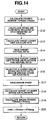
- Fig. 14 is a flow diagram showing an alternative manner of target torque calculation according to a fifth embodiment.
- step S11 the driver's demand torque tTRQdvr is calculated from a predetermined map based on accelerator position ACC and engine speed Ne.
- step S12 the ISC intake air flow rate required at the stoichiometric air-fuel ratio is calculated for increase/decrease control using a comparison between the actual idling speed and the target idling speed.
- step S13 the negative pressure control target intake air flow rate (the target lower limit intake air flow rate) corresponding to the target lower limit negative pressure for deceleration negative pressure control is calculated.
- step S14 the target air-fuel ratio tAFR is read.
- step S15 a correction is made based on the target air-fuel ratio tAFR. That is, the target lower limit intake air flow rate is corrected in accordance with the air-fuel ratio as follows: target lower limit intake air flow rate x 14.7/tAFR.
- step S16 a greater one of the ISC intake air flow rate required at the stoichiometric air-fuel ratio and the negative pressure control target intake air flow rate from step S15 (the target lower limit intake air flow rate) is selected.
- the selected air flow rate is set as an engine demand intake air flow rate.
- step S17 the engine speed Ne is read.
- step S18 the target cylinder intake air flow rate is calculated based on the engine demand intake air flow rate and the engine speed.
- step S19 the target cylinder intake air flow rate is converted to an engine demand torque tTRQeng.
- a target torque is produced in a manner so as to provide a torque increase corresponding to a torque increase demanded by the driver by combining the driver demand torque and the engine demand torque to calculate the target torque. This is effective to provide a response to the driver's demand while taking engine demand into account, so as to improve driving performance.
- the engine demand torque can be set at an appropriate value by selecting a greater one of the idling speed control target torque and the negative pressure control target torque, and setting the selected one as the engine demand torque.
- correction for negative pressure control is made based on the target air-fuel ratio. This allows the invention to be applicable to engines such as direct injection spark-ignition type engines or the like wherein air-fuel ratio changes over a great range.
Landscapes
- Engineering & Computer Science (AREA)
- Chemical & Material Sciences (AREA)
- Combustion & Propulsion (AREA)
- Mechanical Engineering (AREA)
- General Engineering & Computer Science (AREA)
- Electrical Control Of Air Or Fuel Supplied To Internal-Combustion Engine (AREA)
- Control Of Throttle Valves Provided In The Intake System Or In The Exhaust System (AREA)
Claims (10)
- Motor- Drossel- Steuereinheit (20) für ein Fahrzeug mit einem Verbrennungsmotor (1), wobei die Steuereinheit (20) aufweist:einen Berechnungsabschnitt für das Fahrer- Bedarfsdrehmoment (101) zur Berechnung eines Fahrer- Bedarfsdrehmoments, das einer Anforderung des Fahrers auf der Grundlage zumindest der Gaspedalstellung entspricht;eine Berechnungseinheit für das Motor- Bedarfsdrehmoment (103) zur Berechnung eines ersten Parameters, der ein Drehmoment repräsentiert, das der Verbrennungsmotor (1) erfordert, unabhängig von einer Gaspedal- Anforderung des Fahrers;eine Berechnungseinheit für den Mindestluftstrom (105) zur Berechnung eines zweiten Parameters, der einen Mindestluftstrom in den Verbrennungsmotor darstellt, wobei der erste und der zweite Parameter entweder Drehmomente oder Luftströmungsraten repräsentieren;einen Auswahlabschnitt (108), der aus dem ersten Parameter und dem zweiten Pärameter den größeren auswählt; undeinen Kombinationsabschnitt (109), um das Fahrer- Bedarfsdrehmoment mit einem Drehmoment zu kombinieren, das dem von dem Auswahlabschnitt ausgewählten Parameter entspricht, um ein Ziel- Drehmoment zur Steuerung der Luftansaugung des Verbrennungsmotors zu erzeugen.
- Steuereinheit nach Anspruch 1, wobei der zweite Parameter einen Mindestluftstrom in den Verbrennungsmotor zur Ladesteuerung darstellt.
- Steuereinheit nach Anspruch 1, wobei die Steuereinheit eine elektronisch gesteuertes Drosselventil steuert.
- Steuereinheit nach Anspruch 1, wobei der erste Parameter und der zweite Parameter Drehmomente sind.
- Steuereinheit nach Anspruch 1, wobei der erste Parameter und der zweite Parameter Luft- Strömungsraten sind.
- Steuereinheit nach Anspruch 1, wobei der Kombinationsabschnitt das Fahrer-Bedarfsdrehmoment zu einem Drehmoment addiert, das dem Parameter entspricht, der von dem Auswahlabschnitt ausgewählt wurde, um das Ziel- Drehmoment zu erzeugen.
- Steuereinheit nach Anspruch 1, wobei die Berechnungseinheit für den Mindestluftstrom den zweiten Parameter zumindest teilweise auf der Grundlage eines variablen Luft- Kraftstoff- Zielverhältnisses berechnet.
- Steuereinheit nach Anspruch 1, wobei die Berechnungseinheit für das Motor- Bedarfsdrehmoment den ersten Parameter so berechnet, dass während der Leerlaufsteuerung des Motors die Leerlaufdrehzahl des Motors beibehalten wird.
- Steuereinheit nach Anspruch 2, wobei die Berechnungseinheit für den Mindestluftstrom den zweiten Parameter zumindest teilweise auf der Grundlage eines variablen Luft- Kraftstoff- Zielverhältrlisses berechnet.
- Steuereinheit nach Anspruch 9, wobei die Berechnungseinheit für das Motor- Bedarfsdrehmoment den ersten Parameter so berechnet, dass während der Leeriaufsteuerung des Motors die Leerlaufdrehzahl des Motors beibehalten wird.
Applications Claiming Priority (3)
| Application Number | Priority Date | Filing Date | Title |
|---|---|---|---|
| JP16761397A JP3514077B2 (ja) | 1997-06-24 | 1997-06-24 | エンジンのスロットル制御装置 |
| JP16761397 | 1997-06-24 | ||
| JP167613/97 | 1997-06-24 |
Publications (3)
| Publication Number | Publication Date |
|---|---|
| EP0887535A2 EP0887535A2 (de) | 1998-12-30 |
| EP0887535A3 EP0887535A3 (de) | 2000-04-26 |
| EP0887535B1 true EP0887535B1 (de) | 2004-04-21 |
Family
ID=15853038
Family Applications (1)
| Application Number | Title | Priority Date | Filing Date |
|---|---|---|---|
| EP98111453A Expired - Lifetime EP0887535B1 (de) | 1997-06-24 | 1998-06-22 | Drosselklappenkontrolleinrichtung für einen Verbrennungsmotor |
Country Status (5)
| Country | Link |
|---|---|
| US (1) | US6006724A (de) |
| EP (1) | EP0887535B1 (de) |
| JP (1) | JP3514077B2 (de) |
| KR (1) | KR100284463B1 (de) |
| DE (1) | DE69823269T2 (de) |
Families Citing this family (40)
| Publication number | Priority date | Publication date | Assignee | Title |
|---|---|---|---|---|
| JP3627464B2 (ja) * | 1997-08-28 | 2005-03-09 | 日産自動車株式会社 | エンジンの制御装置 |
| DE19740968B4 (de) * | 1997-09-17 | 2007-11-29 | Robert Bosch Gmbh | Verfahren zum Betreiben einer Brennkraftmaschine |
| JPH11182299A (ja) * | 1997-12-15 | 1999-07-06 | Nissan Motor Co Ltd | エンジンのトルク制御装置 |
| DE19814743A1 (de) * | 1998-04-02 | 1999-10-07 | Bosch Gmbh Robert | Verfahren und Vorrichtung zum Betreiben einer Antriebseinheit eines Fahrzeugs |
| US6178371B1 (en) * | 1999-04-12 | 2001-01-23 | Ford Global Technologies, Inc. | Vehicle speed control system and method |
| JP3061795B1 (ja) * | 1999-05-14 | 2000-07-10 | 三菱電機株式会社 | エンジンの吸気量制御装置 |
| JP2000345886A (ja) * | 1999-05-31 | 2000-12-12 | Isuzu Motors Ltd | ディーゼルエンジンの燃料噴射制御装置 |
| DE19928825C2 (de) * | 1999-06-24 | 2003-10-09 | Bosch Gmbh Robert | Verfahren zum Betreiben einer Brennkraftmaschine, Steuergerät für eine Brennkraftmaschine sowie Brennkraftmaschine insbesondere für ein Kraftfahrzeug |
| US6978764B1 (en) | 1999-10-18 | 2005-12-27 | Ford Global Technologies, Inc. | Control method for a vehicle having an engine |
| US6470869B1 (en) | 1999-10-18 | 2002-10-29 | Ford Global Technologies, Inc. | Direct injection variable valve timing engine control system and method |
| US6712041B1 (en) | 1999-10-18 | 2004-03-30 | Ford Global Technologies, Inc. | Engine method |
| US6560527B1 (en) | 1999-10-18 | 2003-05-06 | Ford Global Technologies, Inc. | Speed control method |
| US7398762B2 (en) * | 2001-12-18 | 2008-07-15 | Ford Global Technologies, Llc | Vehicle control system |
| US6279531B1 (en) | 1999-08-09 | 2001-08-28 | Ford Global Technologies, Inc. | System and method for controlling engine torque |
| US7299786B2 (en) | 2004-02-05 | 2007-11-27 | Ford Global Technologies Llc | Vehicle control system |
| FR2810078B1 (fr) * | 2000-06-13 | 2002-10-11 | Peugeot Citroen Automobiles Sa | Procede d'optimisation de fonctionnement d'un vehicule automobile lors de l'utilisation du frein moteur |
| US6584392B1 (en) * | 2000-06-20 | 2003-06-24 | Ford Global Technologies, Inc. | Powertrain output monitor |
| US6536402B2 (en) * | 2001-05-04 | 2003-03-25 | Caterpillar Inc. | Programmable torque limit |
| JP2002371881A (ja) * | 2001-06-13 | 2002-12-26 | Mitsubishi Electric Corp | スロットル制御装置 |
| US6705285B2 (en) * | 2001-10-31 | 2004-03-16 | Daimlerchrysler Corporation | Air flow target determination |
| US6672282B2 (en) | 2002-03-07 | 2004-01-06 | Visteon Global Technologies, Inc. | Increased resolution electronic throttle control apparatus and method |
| CN100520024C (zh) * | 2003-07-08 | 2009-07-29 | 日产自动车株式会社 | 用于内燃发动机的燃烧控制装置和方法 |
| JP2005042661A (ja) | 2003-07-25 | 2005-02-17 | Nissan Motor Co Ltd | 内燃機関の燃焼制御装置 |
| GB2429260A (en) * | 2005-08-04 | 2007-02-21 | Ec Power As | Throttle valve |
| JP4345747B2 (ja) * | 2006-01-30 | 2009-10-14 | トヨタ自動車株式会社 | 内燃機関の制御装置 |
| US7487758B1 (en) | 2006-09-12 | 2009-02-10 | Dedenbear Products, Inc. | Control apparatus for a throttle stop of an internal combustion engine |
| JP4325701B2 (ja) * | 2007-05-16 | 2009-09-02 | トヨタ自動車株式会社 | 内燃機関の制御装置 |
| US8793002B2 (en) * | 2008-06-20 | 2014-07-29 | Caterpillar Inc. | Torque load control system and method |
| US7698049B2 (en) * | 2008-01-09 | 2010-04-13 | Gm Global Technology Operations, Inc. | Speed control in a torque-based system |
| JP5279570B2 (ja) | 2009-03-24 | 2013-09-04 | 本田技研工業株式会社 | エンジンのスロットル制御装置 |
| US8744716B2 (en) * | 2009-12-16 | 2014-06-03 | GM Global Technology Operations LLC | Speed control systems and methods for internal combustion engines |
| JP5263140B2 (ja) * | 2009-12-17 | 2013-08-14 | トヨタ自動車株式会社 | 車両制御システムおよび車両制御方法 |
| US8874331B2 (en) * | 2011-05-16 | 2014-10-28 | Toyota Motor Engineering & Manufacturing North America, Inc. | Method and apparatus for idle speed control based on variable torque converter load |
| DE102012209759B4 (de) * | 2011-06-16 | 2017-06-22 | GM Global Technology Operations, LLC (n.d. Ges. d. Staates Delaware) | Steuerungssystem und verfahren zum koordinieren von drossel und ladedruck |
| CN103975153B (zh) * | 2011-12-08 | 2017-02-15 | 丰田自动车株式会社 | 内燃机的控制装置 |
| JP6318950B2 (ja) * | 2014-07-29 | 2018-05-09 | トヨタ自動車株式会社 | 車両の制御装置 |
| JP6543509B2 (ja) * | 2015-05-13 | 2019-07-10 | 本田技研工業株式会社 | 内燃機関の制御装置 |
| JP6939707B2 (ja) | 2018-05-30 | 2021-09-22 | トヨタ自動車株式会社 | 車両システム |
| JP7096852B2 (ja) * | 2020-02-25 | 2022-07-06 | 本田技研工業株式会社 | エンジン制御装置 |
| JP7400660B2 (ja) * | 2020-08-07 | 2023-12-19 | トヨタ自動車株式会社 | エンジン制御装置 |
Family Cites Families (14)
| Publication number | Priority date | Publication date | Assignee | Title |
|---|---|---|---|---|
| US4951209A (en) | 1986-07-02 | 1990-08-21 | Nissan Motor Co., Ltd. | Induction volume sensing arrangement for internal combustion engine or the like |
| JPH01237333A (ja) * | 1987-10-27 | 1989-09-21 | Japan Electron Control Syst Co Ltd | 内燃機関の制御装置 |
| JP2650034B2 (ja) | 1987-11-04 | 1997-09-03 | 株式会社ユニシアジェックス | 内燃機関の減速制御装置 |
| JP2510877B2 (ja) | 1988-05-23 | 1996-06-26 | 株式会社ユニシアジェックス | 内燃機関の補助空気制御装置 |
| JP2861225B2 (ja) * | 1990-03-26 | 1999-02-24 | 株式会社デンソー | 車両内燃機関系の制御装置 |
| JPH04203250A (ja) * | 1990-11-29 | 1992-07-23 | Mitsubishi Motors Corp | 走行負荷分補償式速度制御部付ドライブバイワイヤ式車両 |
| FR2688546B1 (fr) * | 1992-03-10 | 1996-03-01 | Siemens Automotive Sa | Procede et dispositif de commande d'un moteur a combustion interne. |
| JPH06146933A (ja) * | 1992-10-30 | 1994-05-27 | Daihatsu Motor Co Ltd | 減速時のスロットル開度制御装置 |
| JP3216346B2 (ja) * | 1993-08-26 | 2001-10-09 | 株式会社デンソー | 内燃機関のスロットル弁制御装置 |
| JP3324305B2 (ja) * | 1994-11-25 | 2002-09-17 | 日産自動車株式会社 | 内燃機関の出力制御装置 |
| JPH08193536A (ja) * | 1995-01-18 | 1996-07-30 | Toyota Motor Corp | 筒内噴射式内燃機関の燃料噴射制御装置 |
| JP3201936B2 (ja) * | 1995-09-29 | 2001-08-27 | 株式会社日立製作所 | 筒内噴射エンジンの制御装置 |
| JPH09287513A (ja) * | 1996-02-23 | 1997-11-04 | Nissan Motor Co Ltd | エンジンのトルク制御装置 |
| JPH11107787A (ja) * | 1997-10-02 | 1999-04-20 | Mitsubishi Electric Corp | エンジン制御装置 |
-
1997
- 1997-06-24 JP JP16761397A patent/JP3514077B2/ja not_active Expired - Fee Related
-
1998
- 1998-06-22 EP EP98111453A patent/EP0887535B1/de not_active Expired - Lifetime
- 1998-06-22 DE DE69823269T patent/DE69823269T2/de not_active Expired - Lifetime
- 1998-06-23 KR KR1019980023738A patent/KR100284463B1/ko not_active Expired - Fee Related
- 1998-06-23 US US09/102,366 patent/US6006724A/en not_active Expired - Lifetime
Also Published As
| Publication number | Publication date |
|---|---|
| US6006724A (en) | 1999-12-28 |
| DE69823269D1 (de) | 2004-05-27 |
| EP0887535A2 (de) | 1998-12-30 |
| EP0887535A3 (de) | 2000-04-26 |
| JPH1113516A (ja) | 1999-01-19 |
| KR19990007246A (ko) | 1999-01-25 |
| DE69823269T2 (de) | 2004-08-26 |
| KR100284463B1 (ko) | 2001-03-02 |
| JP3514077B2 (ja) | 2004-03-31 |
Similar Documents
| Publication | Publication Date | Title |
|---|---|---|
| US6006724A (en) | Engine throttle control apparatus | |
| US6279551B1 (en) | Apparatus for controlling internal combustion engine with supercharging device | |
| KR100310094B1 (ko) | 기통내분사형불꽃점화식내연엔진의제어장치 | |
| US5846164A (en) | Apparatus for controlling negative pressure for a brake booster in a diesel engine | |
| US5979397A (en) | Control apparatus for direct injection spark ignition type internal combustion engine | |
| US6006716A (en) | Apparatus for controlling negative pressure in internal combustion engine | |
| US6055476A (en) | Engine torque control system | |
| EP0881375A2 (de) | Leerlaufdrehzahlregler für Brennkraftmaschine | |
| US6145489A (en) | Torque controller for internal combustion engine | |
| US6176227B1 (en) | Control system for cylinder injection type internal combustion engine with exhaust gas recirculation feedback control | |
| US7168238B2 (en) | Method for heating up a catalyst in combustion engines with direct fuel injection | |
| US6512983B1 (en) | Method for determining the controller output for controlling fuel injection engines | |
| AU624556B2 (en) | Method for controlling the quantity of intake air supplied to an internal combustion engine | |
| WO2005017336A1 (ja) | 内燃機関の制御装置 | |
| JP3504067B2 (ja) | エンジン制御装置 | |
| JP3911855B2 (ja) | 直噴火花点火式エンジンの制御装置 | |
| JP3303274B2 (ja) | 電制スロットル式内燃機関の制御装置 | |
| JPH1162658A (ja) | 内燃機関の制御装置 | |
| JP3536596B2 (ja) | 直噴火花点火式内燃機関の燃料噴射制御装置 | |
| JPH09240322A (ja) | 車両パワートレインの制御装置 | |
| US6612284B1 (en) | Device and method for engine control | |
| JPH1136926A (ja) | 筒内噴射式エンジン | |
| JP2000097080A (ja) | エンジンの制御装置 | |
| JPH0577867B2 (de) | ||
| JP2000073822A (ja) | 筒内噴射式エンジンの排気還流制御装置 |
Legal Events
| Date | Code | Title | Description |
|---|---|---|---|
| PUAI | Public reference made under article 153(3) epc to a published international application that has entered the european phase |
Free format text: ORIGINAL CODE: 0009012 |
|
| 17P | Request for examination filed |
Effective date: 19980622 |
|
| AK | Designated contracting states |
Kind code of ref document: A2 Designated state(s): DE FR GB |
|
| AX | Request for extension of the european patent |
Free format text: AL;LT;LV;MK;RO;SI |
|
| PUAL | Search report despatched |
Free format text: ORIGINAL CODE: 0009013 |
|
| AK | Designated contracting states |
Kind code of ref document: A3 Designated state(s): AT BE CH CY DE DK ES FI FR GB GR IE IT LI LU MC NL PT SE |
|
| AX | Request for extension of the european patent |
Free format text: AL;LT;LV;MK;RO;SI |
|
| AKX | Designation fees paid |
Free format text: DE FR GB |
|
| 17Q | First examination report despatched |
Effective date: 20030226 |
|
| GRAP | Despatch of communication of intention to grant a patent |
Free format text: ORIGINAL CODE: EPIDOSNIGR1 |
|
| GRAS | Grant fee paid |
Free format text: ORIGINAL CODE: EPIDOSNIGR3 |
|
| GRAA | (expected) grant |
Free format text: ORIGINAL CODE: 0009210 |
|
| AK | Designated contracting states |
Kind code of ref document: B1 Designated state(s): DE FR GB |
|
| REG | Reference to a national code |
Ref country code: GB Ref legal event code: FG4D |
|
| REF | Corresponds to: |
Ref document number: 69823269 Country of ref document: DE Date of ref document: 20040527 Kind code of ref document: P |
|
| ET | Fr: translation filed | ||
| PLBE | No opposition filed within time limit |
Free format text: ORIGINAL CODE: 0009261 |
|
| STAA | Information on the status of an ep patent application or granted ep patent |
Free format text: STATUS: NO OPPOSITION FILED WITHIN TIME LIMIT |
|
| 26N | No opposition filed |
Effective date: 20050124 |
|
| REG | Reference to a national code |
Ref country code: GB Ref legal event code: 746 Effective date: 20080414 |
|
| REG | Reference to a national code |
Ref country code: FR Ref legal event code: PLFP Year of fee payment: 19 |
|
| REG | Reference to a national code |
Ref country code: FR Ref legal event code: PLFP Year of fee payment: 20 |
|
| PGFP | Annual fee paid to national office [announced via postgrant information from national office to epo] |
Ref country code: DE Payment date: 20170613 Year of fee payment: 20 Ref country code: GB Payment date: 20170621 Year of fee payment: 20 Ref country code: FR Payment date: 20170511 Year of fee payment: 20 |
|
| REG | Reference to a national code |
Ref country code: DE Ref legal event code: R071 Ref document number: 69823269 Country of ref document: DE |
|
| REG | Reference to a national code |
Ref country code: GB Ref legal event code: PE20 Expiry date: 20180621 |
|
| PG25 | Lapsed in a contracting state [announced via postgrant information from national office to epo] |
Ref country code: GB Free format text: LAPSE BECAUSE OF EXPIRATION OF PROTECTION Effective date: 20180621 |