EP0887824B1 - Vakuumschaltvorrichtung mit L-förmiger Anordnung für den festen und den beweglichen Leiter - Google Patents
Vakuumschaltvorrichtung mit L-förmiger Anordnung für den festen und den beweglichen Leiter Download PDFInfo
- Publication number
- EP0887824B1 EP0887824B1 EP98110914A EP98110914A EP0887824B1 EP 0887824 B1 EP0887824 B1 EP 0887824B1 EP 98110914 A EP98110914 A EP 98110914A EP 98110914 A EP98110914 A EP 98110914A EP 0887824 B1 EP0887824 B1 EP 0887824B1
- Authority
- EP
- European Patent Office
- Prior art keywords
- electrode
- movable
- stationary
- conductor
- movable electrode
- Prior art date
- Legal status (The legal status is an assumption and is not a legal conclusion. Google has not performed a legal analysis and makes no representation as to the accuracy of the status listed.)
- Expired - Lifetime
Links
Images




Classifications
-
- H—ELECTRICITY
- H01—ELECTRIC ELEMENTS
- H01H—ELECTRIC SWITCHES; RELAYS; SELECTORS; EMERGENCY PROTECTIVE DEVICES
- H01H33/00—High-tension or heavy-current switches with arc-extinguishing or arc-preventing means
- H01H33/60—Switches wherein the means for extinguishing or preventing the arc do not include separate means for obtaining or increasing flow of arc-extinguishing fluid
- H01H33/66—Vacuum switches
- H01H33/664—Contacts; Arc-extinguishing means, e.g. arcing rings
- H01H33/6643—Contacts; Arc-extinguishing means, e.g. arcing rings having disc-shaped contacts subdivided in petal-like segments, e.g. by helical grooves
-
- H—ELECTRICITY
- H01—ELECTRIC ELEMENTS
- H01H—ELECTRIC SWITCHES; RELAYS; SELECTORS; EMERGENCY PROTECTIVE DEVICES
- H01H31/00—Air-break switches for high tension without arc-extinguishing or arc-preventing means
- H01H31/003—Earthing switches
-
- H—ELECTRICITY
- H01—ELECTRIC ELEMENTS
- H01H—ELECTRIC SWITCHES; RELAYS; SELECTORS; EMERGENCY PROTECTIVE DEVICES
- H01H33/00—High-tension or heavy-current switches with arc-extinguishing or arc-preventing means
- H01H33/60—Switches wherein the means for extinguishing or preventing the arc do not include separate means for obtaining or increasing flow of arc-extinguishing fluid
- H01H33/66—Vacuum switches
- H01H33/666—Operating arrangements
- H01H33/6664—Operating arrangements with pivoting movable contact structure
Definitions
- the present invention relates to a vacuum type switch gear device having an L shaped stationary and movable conductors arrangement and, more specifically, to a composite vacuum type switch gear device in which an arrangement between a movable conductor and arc grooves provided for a movable electrode carried by the movable conductor is, in particular, improved.
- making and breaking operation is performed by opening and closing a pair of electrodes disposed in an opposing manner within a vacuum bulb.
- electrodes provided each at an end of the respective rods are opened and closed.
- a movable electrode is designed to be rotatable around a main axis so as to open and close the same with respect to a stationary electrode.
- An object of the present invention is to provide a vacuum type switch gear device having an L shaped stationary and movable conductors arrangement in which an adverse effect of a current loop flowing through the movable conductor against an arc generated between movable and stationary electrodes is limited to thereby improve its circuit breaking performance and, more specifically, to provide a composite vacuum type switch gear device which permits an active magnetic drive of an arc generated between electrodes along the outer circumference of the electrodes and improves its circuit breaking performance.
- a vacuum type switch gear device having an L shaped stationary and movable conductors arrangement is constituted by a vacuum bulb ; a stationary conductor a part of which is disposed in the vacuum bulb ; a stationary electrode carried by the stationary conductor at one end thereof in the vacuum bulb ; a movable conductor being disposed in the vacuum bulb and being extending substantially orthogonal with respect to the extending direction of the stationary conductor, the movable conductor being supported rotatably by the vacuum bulb ; a movable electrode carried by the movable conductor at one end thereof in the vacuum bulb and being permitted engagement and disengagement thereof with the stationary electrode through rotation of the movable conductor ; a plurality of spiral arc grooves provided on the surface of the stationary electrode facing the movable electrode ; and, a plurality of spiral arc grooves provided on the surface of the movable electrode facing the stationary electrode, wherein a transitive portion from one spiral arc groove to adjacent another spiral arc
- a composite vacuum type switch gear device is constituted by a movable electrode which is designed to open and close with respect to a stationary electrode and a grounding electrode which are disposed in an opposing manner within a vacuum bulb and a movable conductor one end of which carries the movable electrode and the other end of which extends outside from the vacuum bulb, wherein the movable conductor is rotatably supported by a main axis so as to permit opening and closing of the movable electrode with respect to both stationary and grounding electrodes and a plurality of arc grooves are provided on one movable electrode face of the movable electrode which contacts to both stationary and grounding electrodes, and further a portion surrounded by a top end portion of one of the arc grooves, a neighboring other arc groove and the outer circumferential edge portion of the movable electrode is placed so as to face the movable conductor.
- a vacuum bulb 30 is constituted as will be explained herein below and the inside thereof is evacuated and sealed.
- a metal casing 16 At the upper portion of a metal casing 16 an insulator cylinder 2A is provided.
- a stationary rod 4 is fixed by a seal metal fitting 3A provided at the top of the insulator cylinder 2A.
- a seal metal fitting 3C At an insulator cylinder 2C provided at the bottom of the metal casing 16 a seal metal fitting 3C is attached and the displacement of a grounding conductor 42 is permitted by a bellows 6C fixed between the seal metal fitting 3C and the grounding conductor 42.
- a movable rod 5 which is disposed in an orthogonal direction with respect to the stationary rod 4, is extended outside of the vacuum bulb 30, and is held by an insulator cylinder 2B secured to the metal casing 16 through a bellows 6B and a seal metal fitting 3B.
- a movable electrode 9 is connected, and the stationary electrode 8 and the movable electrode 9 are connected to the respective inner ends of the stationary rod 4 and the movable rod 5.
- the movable rod 5 is structured to be rotatable around a main axis 18 as a fulcrum by a four position type operating unit (not shown) and is designed to stop at the following four positions. Namely, a circuit making position Y1 where the movable electrode 9 contacts to the stationary electrode 8, a circuit breaking position Y2 where the movable rod 5 is rotated downward from the circuit making position Y1 to interrupt a current flowing therethrough, a disconnecting position Y3 where the movable rod 5 is further rotated downward to an insulation distance through which such as a lightning surge can be withstood, and a grounding position Y4 where the movable rod 5 is further rotated to contact the movable electrode 9 with the grounding conductor 42.
- a circuit making position Y1 where the movable electrode 9 contacts to the stationary electrode 8
- a circuit breaking position Y2 where the movable rod 5 is rotated downward from the circuit making position Y1 to interrupt a current flowing therethrough
- the stationary electrode 8 and the movable electrode 9 made of a material having a high melting temperature such as Cu-Pb alloy are provided.
- an arc A is concentrically generated at a certain one point between the both stationary and movable electrodes 8 and 9, the surface temperature of the both stationary and movable electrodes 8 and 9 rises and the metal of the both stationary and movable electrodes 8 and 9 is caused to melt and is vaporized, therefore, it is necessary to apply the arc A a magnetic driving force so as to always move or run the arc A between the both stationary and movable electrodes 8 and 9.
- both the stationary and movable electrodes 8 and 9 are provided with a plurality of arc grooves, in the present embodiment three arc grooves 10 (10A, 10B and 10C), so as to apply a magnetic driving force to the arc A.
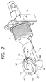
- a transitive portion S from one arc groove to another surrounded by a top end portion 10E of, for example, the arc groove 10A, another arc groove 10B neighboring thereto and an electrode outer circumferential edge 9E is arranged so as to face the movable rod 5, in other words, the projection of the transitive portion S is arranged so as to overlap on the movable rod 5 in vertical direction.
- an electro-magnetic force F2 As illustrated in Figs.1 and 2, through a magnetic field generated by a current flowing through the both stationary and movable electrodes 8 and 9 via the arc A in the arrowed direction, an electro-magnetic force F2 according to Fleming's rule acts on the arc A generated between the both stationary and movable electrodes 8 and 9 in the rightward direction in the drawings.
- the electro-magnetic force F2 is maximized when the arc A is generated at the outer most position P on the movable electrode 9.
- the portion S on the movable electrode 9 is moved in anti-clockwise direction by 30° with respect to the center line O of the movable rod 5.
- the portion S on the movable electrode 9 is moved in anti-clockwise direction by 60° with respect to the center line O of the movable rod 5.
- the electro-magnetic force F2 becomes weaker than the electro-magnetic force F1, namely, electro-magnetic force F1>electro-magnetic force F2.
- the electro-magnetic force F2 cased by a current flowing through the portions S, when the portion S on the movable electrode 9 is shifted in clockwise direction by 30° (-30°) with respect to the center line O of the movable rod 5 as illustrated in Fig.6, is equal to or somewhat stronger than the electro-magnetic force F1, namely, electro-magnetic force F1 ⁇ electro-magnetic force F2.
- the portion S on the movable electrode 9 is moved in clockwise direction by 60° (-60°) with respect to the center line O of the movable rod 5.
- the electro-magnetic force F2 becomes weaker than the electro-magnetic force F1, namely, electro-magnetic force F1>electro-magnetic force F2.
- the movable electrode 9 is in advance connected to the movable rod 5 so that the portion S faces the movable rod 5, there are no possibilities that the portion S is arranged otherwise with respect to the movable rod 5 and the assembly work of the movable electrode 9 with the movable rod 5 is greatly facilitated.
- the connection assembly of the movable electrode 9 with the movable rod 5 is performed such as by integrally molding the both from molten metal and by soldering the movable electrode 9 to the movable rod 5. In these instances the portion S on the movable electrode 9 is of course arranged so as to face the movable rod 5.
- the magnitude of the electro-magnetic force F2 can be freely adjusted by shifting the angle of the portion S with respect to the movable rod 5 in clockwise or anti-clockwise direction, the arc A can be magnetically driven at any radial position along the electrode surface with respect to the outer circumferential edge.
- modifications of the above embodiments are ones in which the portion S is arranged so as to be shifted with respect to the movable rod 5 in a range between 30° in clockwise direction and 30° in anti-clockwise direction, and the modifications can achieve a stable circuit breaking performance without deteriorating their circuit breaking performance.
- the arc grooves can be provided either on the stationary electrode 8 or on the movable electrode 9.
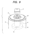
- Fig.9 and Fig.10 show another embodiment in which the stationary rod 4 extends from the back face of the stationary electrode 8 to the outside of the vacuum bulb 30, the external conductor 7 extends in orthogonal direction with respect to the stationary rod 4, a plurality of arc grooves are, provided on the face of the stationary electrode 8 and when assuming a portion formed between a top end portion 10E of the arc groove 10A, another arc groove 10B neighboring thereto and an electrode outer circumferential edge as S, a mark S' is applied on the stationary rod 4 at a visible area on the same side as the portion S, and the external conductor 7 is extended from the stationary rod 4 from the side of the mark S', thereby the assembly work, in which the portion S is arranged so as to correspond to the external conductor 7, is greatly facilitated and the efficiency of the assembly work is significantly improved. Further, with the arrangement of the external conductor 7 with respect to the portion S on the stationary electrode 8, an adverse effect of a current flowing through the external conductor 7 against the arc A is also controlled.
- the movable electrode 9 is in advance connected to the movable rod 5 so that the portion S faces the movable rod 5, there are no possibilities that the portion S is arranged otherwise with respect to the movable rod 5 and the assembly work of the movable electrode 9 with respect to the movable rod 5 is greatly facilitated.
Landscapes
- High-Tension Arc-Extinguishing Switches Without Spraying Means (AREA)
Claims (8)
- Kombinierte Vakuumschaltvorrichtung mit einer bezüglich einer stationären Elektrode (8) zu öffnenden und zu schließenden bewegbaren Elektrode (9) und einer Erdungselektrode (42), die in einem Vakuumkolben (30) einander gegenüber angeordnet sind, sowie mit einem bewegbaren Leiter (5), dessen eines Ende die bewegbare Elektrode (9) trägt und dessen anderes Ende aus dem Vakuumkolben (30) nach außen verläuft, wobei der bewegbare Leiter (5) um eine Hauptachse (18) schwenkbar gelagert ist und dadurch ein Öffnen und Schließen der bewegbaren Elektrode (9) bezüglich sowohl der stationären als auch der Erdungselektrode (8, 42) gestattet, und wobei an einer Elektrodenfläche der bewegbaren Elektrode (9), die sowohl die stationäre als auch die Erdungselektrode (8, 42) kontaktiert, mehrere Bogennuten (10A, 10B, 10C) vorgesehen sind, dadurch gekennzeichnet, daß ein von einem oberen Ende (10E) einer der Bogennoten (10A), einer benachbarten weiteren Bogennut (10B) und dem äußeren Umfangsrandteil (9E) der bewegbaren Elektrode (9) umgebener Bereich (S) dem bewegbaren Leiter (5) zugewandt ist.
- Kombinierte Vakuumschaltvorrichtung mit einer bezüglich einer stationären Elektrode (8) zu öffnenden und zu schließenden bewegbaren Elektrode (9) und einer Erdungselektrode (42), die in einem Vakuumkolben (30) einander gegenüber angeordnet sind, sowie mit einem bewegbaren Leiter (5), dessen eines Ende die bewegbare Elektrode (9) trägt und dessen anderes Ende aus dem Vakuumkolben (30) nach außen verläuft, wobei der bewegbare Leiter (5) um eine Hauptachse (18) schwenkbar gelagert ist und dadurch ein Öffnen und Schließen der bewegbaren Elektrode (9) bezüglich sowohl der stationären als auch der Erdungselektrode (8, 42) gestattet, und wobei an einer Elektrodenfläche der bewegbaren Elektrode (9), die sowohl die stationäre als auch die Erdungselektrode (8, 42) kontaktiert, mehrere Bogennuten (10A, 10B, 10C) vorgesehen sind, dadurch gekennzeichnet, daß eine elektromagnetische Kraft, die auf einen zwischen der bewegbaren Elektrode (9) und der stationären Elektrode (8) entstehenden Lichtbogen (A) einwirkt, dadurch eingestellt wird, daß ein von einem oberen Ende (10E) einer der Bogennuten (10A), einer benachbarten weiteren Bogennut (10B) und dem äußeren Umfangsrandteil (9E) der bewegbaren Elektrode (9) umgebener Bereich (S) relativ zu dem bewegbaren Leiter (5) im oder gegen den Uhrzeigersinn verschoben wird.
- Kombinierte Vakuumschaltvorrichtung mit einer bezüglich einer stationären Elektrode (8) zu öffnenden und zu schließenden bewegbaren Elektrode (9) und einer Erdungselektrode (42), die in einem Vakuumkolben (30) einander gegenüber angeordnet sind, sowie mit einem bewegbaren Leiter (5), dessen eines Ende die bewegbare Elektrode (9) trägt und dessen anderes Ende aus dem Vakuumkolben (30) nach außen verläuft, wobei der bewegbare Leiter (5) um eine Hauptachse (18) schwenkbar gelagert ist und dadurch ein Öffnen und Schließen der bewegbaren Elektrode (9) bezüglich sowohl der stationären als auch der Erdungselektrode (8, 42) gestattet, und wobei an einer Elektrodenfläche der bewegbaren Elektrode (9), die sowohl die stationäre als auch die Erdungselektrode (8, 42) kontaktiert, mehrere Bogennuten (10A, 10B, 10C) vorgesehen sind, dadurch gekennzeichnet, daß ein von einem oberen Ende (10E) einer der Bogennuten (10A), einer benachbarten weiteren Bogennut (10B) und dem äußeren Umfangsrandteil (9E) der bewegbaren Elektrode (9) umgebener Bereich (S) im oder gegen den Uhrzeigersinn in einem Bereich von 30° vom Mittelbereich (O) in Breitenrichtung des bewegbaren Leiters (5) verschoben wird.
- Kombinierte Vakuumschaltvorrichtung mit einer bezüglich einer stationären Elektrode (8) zu öffnenden und zu schließenden bewegbaren Elektrode (9) und einer Erdungselektrode (42), die in einem Vakuumkolben (30) einander gegenüber angeordnet sind, sowie mit einem bewegbaren Leiter (5), dessen eines Ende die bewegbare Elektrode (9) trägt und dessen anderes Ende aus dem Vakuumkolben (30) nach außen verläuft, wobei der bewegbare Leiter (5) um eine Hauptachse (18) schwenkbar gelagert ist und dadurch ein Öffnen und Schließen der bewegbaren Elektrode (9) bezüglich sowohl der stationären als auch der Erdungselektrode (8, 42) gestattet, wobei ein externer Leiter (7) senkrecht zu einem stationären Leiter (4) verläuft, der die stationäre Elektrode (8) trägt und an deren Rückseite aus dem Vakuumkolben (30) nach außen verläuft, und wobei an einer der Fläche der bewegbaren Elektrode zugewandten Fläche der stationären Elektrode mehrere Bogennuten (10A, 10B, 10C) vorgesehen sind, dadurch gekennzeichnet, daß ein von einem oberen Ende (10E) einer der Bogennuten (10A), einer benachbarten weiteren Bogennut (10B) und dem äußeren Umfangsrandteil der stationären Elektrode (8) umgebener Bereich (S) dem externen Leiter (7) zugewandt ist.
- Kombinierte Vakuumschaltvorrichtung nach Anspruch 4, dadurch gekennzeichnet, daß an einem sichtbaren Bereich des stationären Leiters (4) eine Marke (S') an der gleichen Seite vorgesehen ist wie der von einem oberen Ende (10E) einer der Bogennuten (10A), einer benachbarten weiteren Bogennut (10B) und dem äußeren Umfangsrandteil der stationären Elektrode (8) umgebene Bereich (S).
- Vakuumschaltvorrichtung mit L-förmiger Anordnung eines stationären und eines bewegbaren Leiters miteinem Vakuumkolben (30),einem stationären Leiter (4), von dem ein Teil innerhalb des Vakuumkolbens (30) liegt,einer stationären Elektrode (8), die am einen Ende des stationären Leiters (4) innerhalb des Vakuumkolbens (30) angebracht ist,einem bewegbaren Leiter (5), der innerhalb des Vakuumkolbens (30) liegt, im wesentlichen senkrecht zur Erstreckungsrichtung des stationären Leiters (4) verläuft und an dem Vakuumkolben (30) schwenkbar gelagert ist,einer bewegbaren Elektrode (9), die am einen Ende des bewegbaren Leiters (5) innerhalb des Vakuumkolbens (30) angebracht ist und durch Schwenken des bewegbaren Leiters (5) in Eingriff und außer Eingriff mit der stationären Elektrode (8) zu bringen ist,mehreren spiralförmigen Bogennuten (10A, 10B, 10C), die an der der bewegbaren Elektrode (9) zugewandten Fläche der stationären Elektrode (8) vorgesehen sind, undmit mehreren spiralförmigen Bogennuten (10A, 10B, 10C), die an der der stationären Elektrode (8) zugewandten Fläche der bewegbaren Elektrode (9) vorgesehen sind, wobei ein Übergangsbereich (S) von einer spiralförmigen Bogennut (10A) zu einer benachbarten weiteren spiralförmigen Bogennut (10B) an der Fläche der bewegbaren Elektrode (9), der vom Abschlußende (10E) der besagten einen spiralförmigen Nut (10A), dem Anfang der benachbarten spiralförmigen Nut (10B) und dem äußeren Umfangsrandteil (9E) der bewegbaren Elektrode (9) definiert wird, so angeordnet ist, daß er den bewegbaren Leiter (5) in senkrechter Richtung im wesentlichen überlappt.
- Vakuumschaltvorrichtung nach Anspruch 6, wobei ein Übergangsbereich (S) von einer spiralförmigen Bogennut (10A) zu einer benachbarten weiteren spiralförmigen Bogennut (10B) an der Fläche der stationären Elektrode (8), der vom Abschlußende (10E) der besagten einen spiralförmigen Nut (10A), dem Anfang der benachbarten spiralförmigen Nut (10B) und dem äußeren Umfangsrandteil (9E) der stationären Elektrode (8) definiert wird, so angeordnet ist, daß er den Übergangsbereich (S) an der bewegbaren Elektrode (9) in senkrechter Richtung im wesentlichen überlappt.
- Vakuumschaltvorrichtung nach Anspruch 7, mit ferner einem mit dem stationären Leiter (4) verbundenen externen Leiter (7), der im wesentlichen senkrecht zur Erstreckungsrichtung des stationären Leiters (4) verläuft und so angeordnet ist, daß er den Übergangsbereich (S) an der stationären Elektrode (8) in senkrechter Richtung im wesentlichen überlappt.
Applications Claiming Priority (3)
| Application Number | Priority Date | Filing Date | Title |
|---|---|---|---|
| JP17202697 | 1997-06-27 | ||
| JP17202697A JP3462367B2 (ja) | 1997-06-27 | 1997-06-27 | 複合絶縁開閉装置 |
| JP172026/97 | 1997-06-27 |
Publications (2)
| Publication Number | Publication Date |
|---|---|
| EP0887824A1 EP0887824A1 (de) | 1998-12-30 |
| EP0887824B1 true EP0887824B1 (de) | 2000-11-29 |
Family
ID=15934155
Family Applications (1)
| Application Number | Title | Priority Date | Filing Date |
|---|---|---|---|
| EP98110914A Expired - Lifetime EP0887824B1 (de) | 1997-06-27 | 1998-06-15 | Vakuumschaltvorrichtung mit L-förmiger Anordnung für den festen und den beweglichen Leiter |
Country Status (7)
| Country | Link |
|---|---|
| US (1) | US5952636A (de) |
| EP (1) | EP0887824B1 (de) |
| JP (1) | JP3462367B2 (de) |
| KR (1) | KR100308405B1 (de) |
| CN (1) | CN1160753C (de) |
| DE (1) | DE69800412T2 (de) |
| TW (1) | TW388899B (de) |
Families Citing this family (9)
| Publication number | Priority date | Publication date | Assignee | Title |
|---|---|---|---|---|
| US6437275B1 (en) * | 1998-11-10 | 2002-08-20 | Hitachi, Ltd. | Vacuum circuit-breaker, vacuum bulb for use therein, and electrodes thereof |
| JP3589061B2 (ja) * | 1999-01-25 | 2004-11-17 | 株式会社日立製作所 | 真空開閉装置及び真空開閉装置の開閉方法 |
| USD556696S1 (en) * | 2004-11-11 | 2007-12-04 | Abb Technology Ag | Medium and high voltage switch |
| USD558147S1 (en) * | 2005-05-12 | 2007-12-25 | Abb Technology Ag | Medium and high voltage switch |
| USD558148S1 (en) * | 2005-07-19 | 2007-12-25 | Abb Technology Ag | Medium voltage switch with embedded pole |
| USD558149S1 (en) * | 2005-10-28 | 2007-12-25 | Abb Technology Ag | Embedded pole with a vacuum circuit interrupter disposed inside |
| USD554592S1 (en) * | 2006-01-24 | 2007-11-06 | Abb Technology Ag | Embedded pole for a medium voltage switch |
| USD552561S1 (en) * | 2006-04-14 | 2007-10-09 | Mitsubishi Electric Corporation | Gas insulated switchgear |
| JP2021064441A (ja) * | 2019-10-10 | 2021-04-22 | 株式会社日立製作所 | 断路器およびガス絶縁開閉装置 |
Family Cites Families (7)
| Publication number | Priority date | Publication date | Assignee | Title |
|---|---|---|---|---|
| JPS55143727A (en) * | 1979-04-24 | 1980-11-10 | Meidensha Electric Mfg Co Ltd | Vacuum interrupter |
| EP0055008B1 (de) * | 1980-12-22 | 1985-12-11 | Mitsubishi Denki Kabushiki Kaisha | Vakuumschalter |
| JPS61126720A (ja) * | 1984-11-22 | 1986-06-14 | 株式会社日立製作所 | 真空遮断器 |
| DE3644453A1 (de) * | 1986-12-24 | 1988-07-07 | Licentia Gmbh | Schaltstueck fuer leistungsschalter |
| JP2861757B2 (ja) * | 1992-11-10 | 1999-02-24 | 三菱電機株式会社 | 真空バルブの電極装置 |
| EP0740321A3 (de) * | 1995-04-26 | 1998-04-22 | Hitachi, Ltd. | Elektrode für Vakuumlastschalter |
| TW389919B (en) * | 1995-09-27 | 2000-05-11 | Hitachi Ltd | Insulated type switching device |
-
1997
- 1997-06-27 JP JP17202697A patent/JP3462367B2/ja not_active Expired - Lifetime
-
1998
- 1998-06-15 DE DE69800412T patent/DE69800412T2/de not_active Expired - Lifetime
- 1998-06-15 EP EP98110914A patent/EP0887824B1/de not_active Expired - Lifetime
- 1998-06-23 TW TW087110114A patent/TW388899B/zh not_active IP Right Cessation
- 1998-06-25 US US09/104,197 patent/US5952636A/en not_active Expired - Lifetime
- 1998-06-26 CN CNB981151787A patent/CN1160753C/zh not_active Expired - Fee Related
- 1998-06-27 KR KR1019980026537A patent/KR100308405B1/ko not_active Expired - Fee Related
Also Published As
| Publication number | Publication date |
|---|---|
| JPH1125815A (ja) | 1999-01-29 |
| JP3462367B2 (ja) | 2003-11-05 |
| CN1204135A (zh) | 1999-01-06 |
| CN1160753C (zh) | 2004-08-04 |
| KR19990007503A (ko) | 1999-01-25 |
| US5952636A (en) | 1999-09-14 |
| DE69800412T2 (de) | 2001-07-12 |
| DE69800412D1 (de) | 2001-01-04 |
| TW388899B (en) | 2000-05-01 |
| KR100308405B1 (ko) | 2001-11-30 |
| EP0887824A1 (de) | 1998-12-30 |
Similar Documents
| Publication | Publication Date | Title |
|---|---|---|
| US5001313A (en) | Rotating arc circuit breaker with centrifugal extinguishing gas effect | |
| JP3166890B2 (ja) | 回路遮断器の消弧装置 | |
| KR100386845B1 (ko) | 종자계 방식 진공인터럽터용 전극구조 | |
| EP0887824B1 (de) | Vakuumschaltvorrichtung mit L-förmiger Anordnung für den festen und den beweglichen Leiter | |
| US6005213A (en) | Insulated type switchgear device | |
| US3225167A (en) | Vacuum circuit breaker with arc rotation contact means | |
| US4088860A (en) | Vacuum interrupter for high voltage application | |
| US20220285111A1 (en) | High voltage electric power switch with carbon arcing electrodes and carbon dioxide dielectric gas | |
| JP4818530B2 (ja) | 真空バルブ | |
| JPH09512128A (ja) | 遮断室を備えた低圧遮断器 | |
| US4798921A (en) | Vacuum circuit breaker | |
| KR20020090903A (ko) | 배선용 회로 차단기 | |
| EP0071867B1 (de) | Autopneumatischer Druckgasschalter | |
| KR200401665Y1 (ko) | 진공차단기의 진공인터럽터 | |
| JP2517560Y2 (ja) | ガス開閉器 | |
| JP3783414B2 (ja) | 真空遮断器 | |
| JPH04155721A (ja) | 真空バルブ | |
| JPS61220226A (ja) | 真空バルブ | |
| JPH09231854A (ja) | 開閉器 | |
| JP2556429Y2 (ja) | アーク回転式ガス遮断器 | |
| JPH10125184A (ja) | 真空バルブ | |
| JPH08180775A (ja) | 真空バルブ | |
| JP2001229791A (ja) | 真空バルブ | |
| JPS61224229A (ja) | 真空バルブ | |
| KR19990013746A (ko) | 진공차단기 |
Legal Events
| Date | Code | Title | Description |
|---|---|---|---|
| PUAI | Public reference made under article 153(3) epc to a published international application that has entered the european phase |
Free format text: ORIGINAL CODE: 0009012 |
|
| AK | Designated contracting states |
Kind code of ref document: A1 Designated state(s): DE FR GB |
|
| AX | Request for extension of the european patent |
Free format text: AL;LT;LV;MK;RO;SI |
|
| 17P | Request for examination filed |
Effective date: 19990623 |
|
| AKX | Designation fees paid |
Free format text: DE FR GB |
|
| GRAG | Despatch of communication of intention to grant |
Free format text: ORIGINAL CODE: EPIDOS AGRA |
|
| 17Q | First examination report despatched |
Effective date: 19991213 |
|
| GRAG | Despatch of communication of intention to grant |
Free format text: ORIGINAL CODE: EPIDOS AGRA |
|
| GRAG | Despatch of communication of intention to grant |
Free format text: ORIGINAL CODE: EPIDOS AGRA |
|
| GRAH | Despatch of communication of intention to grant a patent |
Free format text: ORIGINAL CODE: EPIDOS IGRA |
|
| GRAH | Despatch of communication of intention to grant a patent |
Free format text: ORIGINAL CODE: EPIDOS IGRA |
|
| GRAA | (expected) grant |
Free format text: ORIGINAL CODE: 0009210 |
|
| AK | Designated contracting states |
Kind code of ref document: B1 Designated state(s): DE FR GB |
|
| REF | Corresponds to: |
Ref document number: 69800412 Country of ref document: DE Date of ref document: 20010104 |
|
| ET | Fr: translation filed | ||
| PLBE | No opposition filed within time limit |
Free format text: ORIGINAL CODE: 0009261 |
|
| STAA | Information on the status of an ep patent application or granted ep patent |
Free format text: STATUS: NO OPPOSITION FILED WITHIN TIME LIMIT |
|
| 26N | No opposition filed | ||
| REG | Reference to a national code |
Ref country code: GB Ref legal event code: IF02 |
|
| REG | Reference to a national code |
Ref country code: FR Ref legal event code: PLFP Year of fee payment: 18 |
|
| PGFP | Annual fee paid to national office [announced via postgrant information from national office to epo] |
Ref country code: GB Payment date: 20150610 Year of fee payment: 18 Ref country code: DE Payment date: 20150609 Year of fee payment: 18 |
|
| PGFP | Annual fee paid to national office [announced via postgrant information from national office to epo] |
Ref country code: FR Payment date: 20150608 Year of fee payment: 18 |
|
| REG | Reference to a national code |
Ref country code: DE Ref legal event code: R119 Ref document number: 69800412 Country of ref document: DE |
|
| GBPC | Gb: european patent ceased through non-payment of renewal fee |
Effective date: 20160615 |
|
| REG | Reference to a national code |
Ref country code: FR Ref legal event code: ST Effective date: 20170228 |
|
| PG25 | Lapsed in a contracting state [announced via postgrant information from national office to epo] |
Ref country code: FR Free format text: LAPSE BECAUSE OF NON-PAYMENT OF DUE FEES Effective date: 20160630 Ref country code: DE Free format text: LAPSE BECAUSE OF NON-PAYMENT OF DUE FEES Effective date: 20170103 |
|
| PG25 | Lapsed in a contracting state [announced via postgrant information from national office to epo] |
Ref country code: GB Free format text: LAPSE BECAUSE OF NON-PAYMENT OF DUE FEES Effective date: 20160615 |