EP0888739A2 - Stuhl, insbesondere Bürostuhl - Google Patents
Stuhl, insbesondere Bürostuhl Download PDFInfo
- Publication number
- EP0888739A2 EP0888739A2 EP98112253A EP98112253A EP0888739A2 EP 0888739 A2 EP0888739 A2 EP 0888739A2 EP 98112253 A EP98112253 A EP 98112253A EP 98112253 A EP98112253 A EP 98112253A EP 0888739 A2 EP0888739 A2 EP 0888739A2
- Authority
- EP
- European Patent Office
- Prior art keywords
- seat
- link
- spring
- chair according
- support
- Prior art date
- Legal status (The legal status is an assumption and is not a legal conclusion. Google has not performed a legal analysis and makes no representation as to the accuracy of the status listed.)
- Withdrawn
Links
- 230000008878 coupling Effects 0.000 claims description 8
- 238000010168 coupling process Methods 0.000 claims description 8
- 238000005859 coupling reaction Methods 0.000 claims description 8
- 230000036316 preload Effects 0.000 claims description 2
- 230000000284 resting effect Effects 0.000 description 3
- 238000010276 construction Methods 0.000 description 2
- 230000007935 neutral effect Effects 0.000 description 2
- 238000004026 adhesive bonding Methods 0.000 description 1
- 230000037396 body weight Effects 0.000 description 1
- 230000006835 compression Effects 0.000 description 1
- 238000007906 compression Methods 0.000 description 1
- 238000005516 engineering process Methods 0.000 description 1
- 238000004519 manufacturing process Methods 0.000 description 1
- NJPPVKZQTLUDBO-UHFFFAOYSA-N novaluron Chemical compound C1=C(Cl)C(OC(F)(F)C(OC(F)(F)F)F)=CC=C1NC(=O)NC(=O)C1=C(F)C=CC=C1F NJPPVKZQTLUDBO-UHFFFAOYSA-N 0.000 description 1
- 238000003466 welding Methods 0.000 description 1
Images


Classifications
-
- A—HUMAN NECESSITIES
- A47—FURNITURE; DOMESTIC ARTICLES OR APPLIANCES; COFFEE MILLS; SPICE MILLS; SUCTION CLEANERS IN GENERAL
- A47C—CHAIRS; SOFAS; BEDS
- A47C1/00—Chairs adapted for special purposes
- A47C1/02—Reclining or easy chairs
- A47C1/031—Reclining or easy chairs having coupled concurrently adjustable supporting parts
- A47C1/032—Reclining or easy chairs having coupled concurrently adjustable supporting parts the parts being movably-coupled seat and back-rest
- A47C1/03205—Reclining or easy chairs having coupled concurrently adjustable supporting parts the parts being movably-coupled seat and back-rest having adjustable and lockable inclination
- A47C1/03238—Reclining or easy chairs having coupled concurrently adjustable supporting parts the parts being movably-coupled seat and back-rest having adjustable and lockable inclination by means of peg-and-notch or pawl-and-ratchet mechanism
-
- A—HUMAN NECESSITIES
- A47—FURNITURE; DOMESTIC ARTICLES OR APPLIANCES; COFFEE MILLS; SPICE MILLS; SUCTION CLEANERS IN GENERAL
- A47C—CHAIRS; SOFAS; BEDS
- A47C1/00—Chairs adapted for special purposes
- A47C1/02—Reclining or easy chairs
- A47C1/031—Reclining or easy chairs having coupled concurrently adjustable supporting parts
- A47C1/032—Reclining or easy chairs having coupled concurrently adjustable supporting parts the parts being movably-coupled seat and back-rest
- A47C1/03261—Reclining or easy chairs having coupled concurrently adjustable supporting parts the parts being movably-coupled seat and back-rest characterised by elastic means
- A47C1/03272—Reclining or easy chairs having coupled concurrently adjustable supporting parts the parts being movably-coupled seat and back-rest characterised by elastic means with coil springs
- A47C1/03274—Reclining or easy chairs having coupled concurrently adjustable supporting parts the parts being movably-coupled seat and back-rest characterised by elastic means with coil springs of torsion type
-
- A—HUMAN NECESSITIES
- A47—FURNITURE; DOMESTIC ARTICLES OR APPLIANCES; COFFEE MILLS; SPICE MILLS; SUCTION CLEANERS IN GENERAL
- A47C—CHAIRS; SOFAS; BEDS
- A47C1/00—Chairs adapted for special purposes
- A47C1/02—Reclining or easy chairs
- A47C1/031—Reclining or easy chairs having coupled concurrently adjustable supporting parts
- A47C1/032—Reclining or easy chairs having coupled concurrently adjustable supporting parts the parts being movably-coupled seat and back-rest
- A47C1/03255—Reclining or easy chairs having coupled concurrently adjustable supporting parts the parts being movably-coupled seat and back-rest with a central column, e.g. rocking office chairs
-
- A—HUMAN NECESSITIES
- A47—FURNITURE; DOMESTIC ARTICLES OR APPLIANCES; COFFEE MILLS; SPICE MILLS; SUCTION CLEANERS IN GENERAL
- A47C—CHAIRS; SOFAS; BEDS
- A47C1/00—Chairs adapted for special purposes
- A47C1/02—Reclining or easy chairs
- A47C1/031—Reclining or easy chairs having coupled concurrently adjustable supporting parts
- A47C1/032—Reclining or easy chairs having coupled concurrently adjustable supporting parts the parts being movably-coupled seat and back-rest
- A47C1/03261—Reclining or easy chairs having coupled concurrently adjustable supporting parts the parts being movably-coupled seat and back-rest characterised by elastic means
- A47C1/03266—Reclining or easy chairs having coupled concurrently adjustable supporting parts the parts being movably-coupled seat and back-rest characterised by elastic means with adjustable elasticity
Definitions
- the invention relates to a chair which can be tilted backwards from a rest position a seat and a backrest (EP 0 250 207 B1).
- a chair which can be tilted backwards from a rest position a seat and a backrest (EP 0 250 207 B1).
- a coupling gear in the form of a four-swivel chain as Guide gear controlled.
- Their handlebars are formed by the seat support and with a base rigidly connected base handlebar, one above in approximate Parallel position handlebars and two of the two aforementioned handlebars at their ends connecting links, namely one below the front edge of the seat arranged front link and one below the rear seating area arranged rear link carrying the backrest at its end.
- the four-swivel chain that controls the inclination movement of the known chair one with its ends on the front joint of the seat link and pressurized gas spring on the base to the seat link each from a backward tilted position to an approximately horizontal resting position to reset.
- the leg spring spreads with its legs the seat link and the Basic handlebars apart. As a result, it provides the seat handlebar carrying the seat board each from a backward tilt position to an approximately horizontal rest position back. By this spring force, the angle between the steering lever and the articulated rear link spread.
- the posi tion of the leg spring in the area of the swivel between the seat link and the base handlebar connected to the base has unfavorable pressure and lever ratios result from the weight of the seated person.
- the height Loading the leg spring requires a large dimension. Furthermore the leg spring forms an additional component to the handlebars of the four-swivel chain.
- the sprung seat and backrest is made of relatively thin, flexible Material made seat plate with its front area fixed with an extension arm of the stand connected. With its rear end, the seat plate rests on one Leg of a leg spring, which is held with its spiral on the base of the chair is.
- the leg of the leg spring is at the bottom of the rear end the seat plate in sleeves of a support part for the backrest can be moved longitudinally guided.
- the inclination of the seat and backrest are based with this chair alone on the flexibility of the seat plate and by means of it a leg spring supporting a thrust guide.
- the invention has for its object to constructively simplify a chair of the type mentioned with a guide gear for controlling the inclination movement.
- This object is solved by claim 1.
- the torsion spring used according to the invention - also in the specialist literature as Leg spring "- not only forms the return spring in a single component, but also, with its spring end or spring leg pointing towards the rear of the seat, also forms at least the essential part of the return link of the coupling mechanism.
- the rear leg of the torsion spring forming the return link is - in relation to the seat position tilted backwards - biased in the direction of a seat return to its rest position or in a slightly forward-tilted starting position.
- the torsion spring forms with its spring body resting on the seat support in addition, the joint axis between in a single component Seat carrier and rear link.
- This hinge axis can also in Compared to the previously known chair as a physical component is eliminated.
- the imaginary The hinge axis between the seat bracket and the return link is the central axis of the spring body the torsion spring.
- the adjustment device is useful a single, acting together on both front spring ends, on Seat support threaded adjustment screw.
- Claim 1 means a further design and manufacturing simplification while ensuring a firm, positive connection between the return link spring end of the torsion spring (s) and both the backrest as well as the seat handlebar.
- the seat depth of the chair can be particularly easily change. For this, e.g. as a seat handlebar only one on top with one T-shaped grooved, essentially straight profile strut used become.
- the seat or backrest inclination of the chair can also fix in different positions. There are also no expensive means for this necessary (claim 16).
- the mechanism for tilt adjustment can be found in easily encapsulated to accommodate according to claim 17 and / or 18.
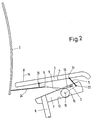
- the chair contains a seat 1 and a backrest 2, which are from a neutral position with a substantially horizontally oriented seat 1 (FIG. 3) about 4 ° to the front (Fig. 2) and an even larger angle to the rear (Fig. 1) is inclinable.
- the tilt movement is controlled by a four-swivel chain as tilt kinematics, its plane of movement runs parallel to the drawing planes of Fig. 1-4 and the is functionally formed by the base link articulated in swivel joints 3, the seat link 4 and through the two connecting these links 3, 4 at their ends to one another, more upright handlebar, namely through the front link 5 and the Return link 6.
- the return link 6 is only functional in FIGS. 1 and 2 Illustrated handlebar, which is physically broken by components with one of the connecting lines shown deviating course is performed.
- the seat link 4 carries the seat surface 1.
- the base link 3 is physically formed by the seat support 7 and this is rigidly connected to the base 8, the footprint on Floor is not shown.
- the rear link 6 is turned by the rear facing the rear Spring end 9 of a torsion spring 10 at least partially formed.
- the torsion spring 10 sits with its spring body 11 on the floor 12 of the seat support 7.
- the torsion spring 10 is supported with its front spring end 13 on the seat support 7, like that shown in FIGS. 1 and 2 by a schematically hatched Holding the spring end 13 is shown. Functionally as a rear link, at least partially effective rear spring end 9 of the torsion spring 10 is in the return direction 14 biased.
- the torsion spring 10 forms with its central longitudinal axis 15 even the hinge axis between seat support 7 and rear link 9.
- the bottom 12 of the seat support 7 is in the manner of one of the shell shape of the spring body 11 adapted bearing shell 16 empty.
- the mean vertical plane of movement 17 (FIG. 5) is the plane of symmetry of the Tilt kinematics. Parallel to it on both sides is a four-swivel chain as Control means for the inclination movement of seat 1 and backrest 2 available.
- the seat support 7 is a shell-like upward as a hinge support for the two joints of the base link 3 effective housing with the middle on both sides Plane of movement 17 to this approximately parallel side walls 18, 19.
- the front spring ends 13 of the torsion springs 10 are connected to the seat support 7 connected adjusting device 20 is supported for the spring tension.
- the adjustment device is by a handwheel 21 from the bottom of the seat support 7 forth adjustable, screw-mounted adjusting screw 22 in the seat support 7, which the front spring ends 13 of the torsion spring 10 acted in the biasing direction 23.
- the shaft of the adjusting screw 22 is on both sides of the front spring ends 13 flanked (Fig. 5).
- torsion springs 10 can also be a single double Torsion spring (not shown) with inner, the front spring ends 13th equivalent support leg can be used.
- the backrest 2 is each with a tubular spur end 24 on a return link spring end 9 postponed. In the deferred position it can e.g. integrally connected by welding or gluing to the spring end 9 be.
- the two spur ends 24 also carry what is firmly connected to them Swivel joint 25 between return link spring end 9 and seat link 4.
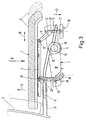
- the seat link 4 contains an open top, parallel to the middle plane of movement 17 running cross-sectional profile for adjustable in the seat depth direction 26 (Fig. 3) Guiding and holding the seat shell 27 forming the seat surface 1.
- a locking mechanism for fixing different Seat inclinations available It is formed by one with its upper one End hung on the swivel 25 between the seat link 4 and the rear link 9 Latching sword 28, the different inclination positions of the seat link 4 assigned recesses 29 with one arranged on the seat support 7 Lock bar 30 cooperate as a lock.
- the locking bolt 30 is on the seat support 7 against the locking sword 28 mounted longitudinally so that he can choose can be inserted into one of the recesses 29.
- the spring bodies 11 of the torsion springs 10 are through side walls 38, 39 of the seat support 7 shielded from the outside.
- the front spring ends 13 of the torsion springs 10 are through side walls 31 of the seat support 7 to the side and to the front encapsulated. With 31 and 32 the rotary joints are marked with which the Front link 5 of one of the two four-link chains on the seat support 7 on the one hand and is articulated on the seat link 4 on the other hand.
Landscapes
- Health & Medical Sciences (AREA)
- Dentistry (AREA)
- General Health & Medical Sciences (AREA)
- Chairs Characterized By Structure (AREA)
- Hydrogenated Pyridines (AREA)
- Chairs For Special Purposes, Such As Reclining Chairs (AREA)
Abstract
Description
- Fig. 1
- eine schematisierte Seitenansicht der für die Neigungskinematik verantwortlichen Teile des Stuhls in nach hinten zurückgeneigter Endstellung.
- Fig. 2
- eine Darstellung analog Fig. 1 in nach vorne geneigter Endstellung der wesentlichen Teile der Neigungskinematik.
- Fig. 3
- eine Seitenansicht - teilweise im Schnitt - des Mittelteils des Stuhles in horizontaler Neutralstellung der Sitzebene mit den für die Neigungskinematik wesentlichen Teilen.
- Fig. 4
- eine Darstellung analog Fig. 3 in nach vorne geneigter Endposition der Sitzfläche.
- Fig. 5
- eine Draufsicht auf die wesentlichen Teile der Neigungskinematik des Sitzes in Pfeilrichtung V von Fig. 3.
- 1
- Sitzfläche
- 2
- Rückenlehne
- 3
- Basislenker
- 4
- Sitzlenker
- 5
- Vorderlenker
- 6
- Rücklenker
- 7
- Sitzträger
- 8
- Standfuß
- 9
- Rücklenker-Federende
- 10
- Drehfeder
- 11
- Federkörper
- 12
- Boden
- 13
- vorderes Federende
- 14
- Rückstellrichtung
- 15
- Mittellängsachse
- 16
- Lagerschale
- 17
- mittl. Bewegungsebene
- 18
- Seitenwand
- 19
- Seitenwand
- 20
- Verstelleinrichtung
- 21
- Handrad
- 22
- Verstellschraube
- 23
- Vorspannrichtung
- 24
- Spornende
- 25
- Drehgelenk
- 26
- Sitztiefenrichtung
- 27
- Sitzschale
- 28
- Rastschwert
- 29
- Rastausnehmung
- 30
- Sperriegel
- 31
- Drehgelenk
- 32
- Drehgelenk
- 38
- Seitenwand
- 39
- Seitenwand
Claims (18)
- Stuhl mit aus einer Ruheposition nach hinten neigbarund mit einem die in einer vertikalen Bewegungsebene verlaufende Neigungsbewegung steuernden Führungsgetriebe in Form eines Koppelgetriebes, welches in Form einer Getriebekette aneinandergelenkteiner Sitzfläche (1) undeiner Rückenlehne (2)enthält, wobei diese Getriebekette von einer Rückstellfeder in Richtung auf die Ruheposition beaufschlagt ist,a) einen mit einem Standfuß (8) verbundenen Sitzträger (7) als Basislenker(3)b) einen darüber verlaufenden Sitzlenker (4) undc) als Verbindungsglied zwischen beiden einen an seinem Ende die Rückenlehne tragenden Rücklenker (6)
dadurch gekennzeichnet,
daß die Rückstellfeder eine Drehfeder (10) mit etwa die Gelenkachse (15) zwischen Sitzträger (7) und Rücklenker (9) umgebendem oder selbst bildendem Federkörper (11) ist, welche Drehfeder (10)mit ihrem vorderen Federende (13) am Sitzträger (7) abgestützt undmit ihrem rückwärtigen Federende (9) mindestens teilweise den dadurch in Rückstellrichtung (14) vorgespannten Rücklenker (6) bildet. - Stuhl nach Anspruch 1,
dadurch gekennzeichnet, daß das Koppelgetriebe eine Vierdrehgelenkkette mit weiterhin einem zwischen Basislenker (3) und Sitzlenker (4) angeordneten Vorderlenker (5) ist. - Stuhl nach Anspruch 1 oder 2,
dadurch gekennzeichnet, daß die Drehfeder (10) mit ihrem Federkörper (11) am Sitzträger (7) aufliegt. - Stuhl nach Anspruch 3,
dadurch gekennzeichnet, daß der Boden (12) des Stützträgers (7) nach Art einer der Mantelform des Federkörpers (11) angepaßten Lagerschale (16) ausgemuldet ist. - Stuhl nach einem oder mehreren der vorhergehenden Ansprüche,
gekennzeichnet durch je eine beidseitig parallel zur mittleren vertikalen Bewegungsebene (17) positionierte Kette als Führungsgetriebe für die Neigungsbewegung von Sitzfläche (1) und Rückenlehne (2). - Stuhl nach Anspruch 5,
dadurch gekennzeichnet, daß der Sitzträger (7) ein schalenartig nach oben als Gelenkträger wirksames Gehäuse mit beiderseits der mittleren Bewegungsebene (17) zu dieser angenähert parallelen Seitenwänden (18,19) bildet, deren jede funktionsmäßig als den Vorderlenker (5) der Vierdrehgelenkkette oder das Schubgelenk einer Schubkurbelkette tragender Basislenker (3) der beiden Ketten wirksam ist. - Stuhl nach einem oder mehreren der vorhergehenden Ansprüche,
gekennzeichnet durch zwei mit etwa koaxialen Federkörpern (11) und gegenüber der mittleren Bewegungsebene (17) außenliegenden Rücklenker-Federenden (9) am Sitzträger (7) positionierte Drehfedern (10). - Stuhl nach Anspruch 7,
dadurch gekennzeichnet, daß die vorderen Federenden (13) der Drehfedern (10) an einer mit dem Sitzträger (7) verbundenen Verstelleinrichtung (20) für die Federvorspannung abgestützt sind. - Stuhl nach Anspruch 8,
gekennzeichnet durch eine in der mittleren Bewegungsebene (17) längsverstellbare, die vorderen Federenden (13) in Vorspannrichtung (23) beaufschlagende Verstellschraube (22). - Stuhl nach Anspruch 8 oder 9,
dadurch gekennzeichnet, daß der Schaft der Verstellschraube (22) beidseitig von den vorderen Federenden (13) flankiert ist. - Stuhl nach einem oder mehreren der Ansprüche 5 bis 10,
gekennzeichnet durch anstelle zweier Drehfedern (10) eine doppelte Drehfeder mit innenliegendem Stützschenkel. - Stuhl nach einem oder mehreren der vorhergehenden Ansprüche,
dadurch gekennzeichnet, daß die Rücklehne (2) mit jeweils einem rohrartigen Spornende (24) auf einem Rücklenker-Federende (9) aufgeschoben aufsitzt. - Stuhl nach Anspruch 12,
dadurch gekennzeichnet, daß das Spornende (24) das Drehgelenk (25) zwischen Rücklenker (9) und Sitzlenker (4) trägt. - Stuhl nach einem oder mehreren der vorhergehenden Ansprüche,
dadurch gekennzeichnet, daß der Sitzlenker (4) ein nach oben offenes, parallel zur mittleren Bewegungsebene (17) verlaufendes Querschnittsprofil zur in Sitztiefenrichtung (26) verstellbaren Führung und Halterung einer Sitzschale (27) enthält. - Stuhl nach einem oder mehreren der vorhergehenden Ansprüche,
gekennzeichnet durch ein zwischen Sitzträger (7) und Sitzlenker (4) wirksames Formgesperre zur Fixierung unterschiedlicher Sitzneigungen. - Stuhl nach Anspruch 14,
dadurch gekennzeichnet, daß das Formgesperre durch ein mit seinem oberen Ende am Drehgelenk (25) zwischen Sitzlenker (4) und Rücklenker (9) aufgehängtes Rastschwert (28) gebildet ist, dessen unterschiedlichen Neigungsstellungen des Sitzlenkers (4) zugeordnete Rastausnehmungen (29) mit einem am Sitzträger (7) angeordneten Sperriegel (30) als Sperrer zusammenwirken. - Stuhl nach einem oder mehreren der vorhergehenden Ansprüche,
dadurch gekennzeichnet, daß die Federkörper (11) der Drehfeder(n) (10) durch Seitenwände (38,39) nach außen abgeschirmt innerhalb des Sitzträgers (7) einliegen. - Stuhl nach einem oder mehreren der vorhergehenden Ansprüche,
dadurch gekennzeichnet, daß die vorderen Federenden (13) der Drehfeder(n) (10) durch Seitenwände (31) des Sitzträgers (7) zur Seite und nach vorne hin gekapselt sind.
Applications Claiming Priority (2)
| Application Number | Priority Date | Filing Date | Title |
|---|---|---|---|
| DE19728838 | 1997-07-05 | ||
| DE19728838A DE19728838C1 (de) | 1997-07-05 | 1997-07-05 | Stuhl, insbesondere Bürostuhl |
Publications (2)
| Publication Number | Publication Date |
|---|---|
| EP0888739A2 true EP0888739A2 (de) | 1999-01-07 |
| EP0888739A3 EP0888739A3 (de) | 2000-05-17 |
Family
ID=7834814
Family Applications (1)
| Application Number | Title | Priority Date | Filing Date |
|---|---|---|---|
| EP98112253A Withdrawn EP0888739A3 (de) | 1997-07-05 | 1998-07-02 | Stuhl, insbesondere Bürostuhl |
Country Status (2)
| Country | Link |
|---|---|
| EP (1) | EP0888739A3 (de) |
| DE (2) | DE29723702U1 (de) |
Cited By (3)
| Publication number | Priority date | Publication date | Assignee | Title |
|---|---|---|---|---|
| EP1060694A1 (de) | 1999-06-17 | 2000-12-20 | König + Neurath AG | Stuhl, insbesondere Bürostuhl |
| WO2015196850A1 (zh) * | 2014-06-26 | 2015-12-30 | 陈国巨 | 椅背后仰时坐垫前移并同时下降的椅子 |
| US11812870B2 (en) | 2021-02-10 | 2023-11-14 | Steelcase Inc. | Body support structure |
Families Citing this family (2)
| Publication number | Priority date | Publication date | Assignee | Title |
|---|---|---|---|---|
| DE10123231C2 (de) * | 2001-05-12 | 2003-05-15 | Roeder Haworth Buero Sitzmoebe | Bürostuhl |
| AT504897B1 (de) * | 2007-05-07 | 2008-09-15 | Hansen Eckhard Dipl Ing | Sitzmöbel |
Citations (4)
| Publication number | Priority date | Publication date | Assignee | Title |
|---|---|---|---|---|
| WO1983000610A1 (en) | 1981-08-19 | 1983-03-03 | Giroflex Entwicklungs Ag | Chair |
| EP0250207B1 (de) | 1986-06-16 | 1992-06-10 | Mines & West Business Furniture Limited | Verstellbare Stühle |
| DE4100641A1 (de) | 1991-01-11 | 1992-07-16 | Kloeber Gmbh & Co | Arbeitsstuhl mit synchron-neigungsmechanik |
| DE3930361C2 (de) | 1989-09-12 | 1993-11-04 | Simon Desanta | Stuhl, insbesondere buerostuhl |
Family Cites Families (5)
| Publication number | Priority date | Publication date | Assignee | Title |
|---|---|---|---|---|
| DE3139448C2 (de) * | 1981-10-03 | 1984-06-07 | Kusch & Co Sitzmöbelwerke KG, 5789 Hallenberg | Stuhl |
| US5050931A (en) * | 1986-04-10 | 1991-09-24 | Steelcase Inc. | Controlled deflection front lip for seating |
| US5035466A (en) * | 1989-04-03 | 1991-07-30 | Krueger International, Inc. | Ergonomic chair |
| US5029940A (en) * | 1990-01-16 | 1991-07-09 | Westinghouse Electric Corporation | Chair tilt and chair height control apparatus |
| JPH0817730B2 (ja) * | 1991-05-21 | 1996-02-28 | 株式会社イトーキ | 背と座がシンクロ動作する椅子におけるシェル構造体 |
-
1997
- 1997-07-05 DE DE29723702U patent/DE29723702U1/de not_active Expired - Lifetime
- 1997-07-05 DE DE19728838A patent/DE19728838C1/de not_active Expired - Lifetime
-
1998
- 1998-07-02 EP EP98112253A patent/EP0888739A3/de not_active Withdrawn
Patent Citations (4)
| Publication number | Priority date | Publication date | Assignee | Title |
|---|---|---|---|---|
| WO1983000610A1 (en) | 1981-08-19 | 1983-03-03 | Giroflex Entwicklungs Ag | Chair |
| EP0250207B1 (de) | 1986-06-16 | 1992-06-10 | Mines & West Business Furniture Limited | Verstellbare Stühle |
| DE3930361C2 (de) | 1989-09-12 | 1993-11-04 | Simon Desanta | Stuhl, insbesondere buerostuhl |
| DE4100641A1 (de) | 1991-01-11 | 1992-07-16 | Kloeber Gmbh & Co | Arbeitsstuhl mit synchron-neigungsmechanik |
Cited By (4)
| Publication number | Priority date | Publication date | Assignee | Title |
|---|---|---|---|---|
| EP1060694A1 (de) | 1999-06-17 | 2000-12-20 | König + Neurath AG | Stuhl, insbesondere Bürostuhl |
| WO2015196850A1 (zh) * | 2014-06-26 | 2015-12-30 | 陈国巨 | 椅背后仰时坐垫前移并同时下降的椅子 |
| US11812870B2 (en) | 2021-02-10 | 2023-11-14 | Steelcase Inc. | Body support structure |
| US12207737B2 (en) | 2021-02-10 | 2025-01-28 | Steelcase Inc. | Body support structure |
Also Published As
| Publication number | Publication date |
|---|---|
| EP0888739A3 (de) | 2000-05-17 |
| DE29723702U1 (de) | 1998-12-24 |
| DE19728838C1 (de) | 1999-01-14 |
Similar Documents
| Publication | Publication Date | Title |
|---|---|---|
| DE3930983C2 (de) | Sitzmöbel mit neigungsverstellbarer Sitzfläche | |
| DE19823632C1 (de) | Stuhl, insbesondere Bürostuhl | |
| DE60300064T2 (de) | Stuhl mit beweglichem Sitz und Rückenlehne | |
| DE3741472C2 (de) | ||
| EP0884964B1 (de) | Stuhl, insbesondere bürostuhl | |
| DE10226717B4 (de) | Gestell eines Kraftfahrzeugsitzes mit einem Sitzträger und einem Polsterträger | |
| DE102007042032B3 (de) | Stuhl, insbesondere ein Zahnarztstuhl, aufweisend eine Sitzfläche mit neigbaren Beinauflagen | |
| DE3232771A1 (de) | Arbeits-sitzmoebel | |
| EP0265782A2 (de) | Sitzmöbel | |
| DE2940250A1 (de) | Ergonomischer stuhl | |
| EP0237825A2 (de) | Sitzmöbel | |
| EP0114600B1 (de) | Stuhl, insbesondere Bürostuhl | |
| EP0582818A1 (de) | Stuhl, insbesondere Bürostuhl | |
| DE3844102A1 (de) | Sitz fuer einen buerostuhl od. dgl. | |
| EP2070446B1 (de) | Bürostuhl mit neigbarer Rückenlehne und Mitteln zur Neigungsbegrenzung der Rückenlehne | |
| EP0820713A2 (de) | Bewegungsstuhl | |
| DE10026531C2 (de) | Stuhl | |
| EP0888739A2 (de) | Stuhl, insbesondere Bürostuhl | |
| DE10393254T5 (de) | Verstellbare Anordnung eines Stuhls | |
| DE3634055A1 (de) | Sitzmoebel | |
| DE10123231C2 (de) | Bürostuhl | |
| DE69714910T2 (de) | Verstellvorrichtung | |
| DE102019131428B4 (de) | Sitzmöbel | |
| EP0056454A2 (de) | Sitzmöbel, insbesondere drehbarer Bürostuhl | |
| DE1529417B2 (de) | Schaukelteil |
Legal Events
| Date | Code | Title | Description |
|---|---|---|---|
| PUAI | Public reference made under article 153(3) epc to a published international application that has entered the european phase |
Free format text: ORIGINAL CODE: 0009012 |
|
| AK | Designated contracting states |
Kind code of ref document: A2 Designated state(s): AT CH DE ES FR GB IT LI NL PT |
|
| AX | Request for extension of the european patent |
Free format text: AL;LT;LV;MK;RO;SI |
|
| RIN1 | Information on inventor provided before grant (corrected) |
Inventor name: POTRYKUS, MARTIN Inventor name: SANDER, ARMIN |
|
| PUAL | Search report despatched |
Free format text: ORIGINAL CODE: 0009013 |
|
| AK | Designated contracting states |
Kind code of ref document: A3 Designated state(s): AT BE CH CY DE DK ES FI FR GB GR IE IT LI LU MC NL PT SE |
|
| AX | Request for extension of the european patent |
Free format text: AL;LT;LV;MK;RO;SI |
|
| 17P | Request for examination filed |
Effective date: 20000608 |
|
| RAP1 | Party data changed (applicant data changed or rights of an application transferred) |
Owner name: KOENIG + NEURATH AG |
|
| AKX | Designation fees paid |
Free format text: AT CH DE ES FR GB LI NL PT |
|
| RBV | Designated contracting states (corrected) |
Designated state(s): AT CH DE ES FR GB IT LI NL PT |
|
| RIN1 | Information on inventor provided before grant (corrected) |
Inventor name: POTRYKUS, MARTIN Inventor name: SANDER, ARMIN |
|
| 17Q | First examination report despatched |
Effective date: 20020618 |
|
| STAA | Information on the status of an ep patent application or granted ep patent |
Free format text: STATUS: THE APPLICATION HAS BEEN WITHDRAWN |
|
| 18W | Application withdrawn |
Withdrawal date: 20021128 |