EP0888811A2 - Mischvorrichtung - Google Patents
Mischvorrichtung Download PDFInfo
- Publication number
- EP0888811A2 EP0888811A2 EP98305267A EP98305267A EP0888811A2 EP 0888811 A2 EP0888811 A2 EP 0888811A2 EP 98305267 A EP98305267 A EP 98305267A EP 98305267 A EP98305267 A EP 98305267A EP 0888811 A2 EP0888811 A2 EP 0888811A2
- Authority
- EP
- European Patent Office
- Prior art keywords
- shaft
- disc
- mixing
- container
- mixing apparatus
- Prior art date
- Legal status (The legal status is an assumption and is not a legal conclusion. Google has not performed a legal analysis and makes no representation as to the accuracy of the status listed.)
- Withdrawn
Links
Images


Classifications
-
- B—PERFORMING OPERATIONS; TRANSPORTING
- B01—PHYSICAL OR CHEMICAL PROCESSES OR APPARATUS IN GENERAL
- B01F—MIXING, e.g. DISSOLVING, EMULSIFYING OR DISPERSING
- B01F27/00—Mixers with rotary stirring devices in fixed receptacles; Kneaders
- B01F27/05—Stirrers
- B01F27/07—Stirrers characterised by their mounting on the shaft
- B01F27/071—Fixing of the stirrer to the shaft
-
- B—PERFORMING OPERATIONS; TRANSPORTING
- B01—PHYSICAL OR CHEMICAL PROCESSES OR APPARATUS IN GENERAL
- B01F—MIXING, e.g. DISSOLVING, EMULSIFYING OR DISPERSING
- B01F27/00—Mixers with rotary stirring devices in fixed receptacles; Kneaders
- B01F27/05—Stirrers
- B01F27/07—Stirrers characterised by their mounting on the shaft
- B01F27/073—Stirrers characterised by their mounting on the shaft with stirring elements moving with respect to the stirrer shaft, e.g. floating or comprising contracting chambers
-
- B—PERFORMING OPERATIONS; TRANSPORTING
- B01—PHYSICAL OR CHEMICAL PROCESSES OR APPARATUS IN GENERAL
- B01F—MIXING, e.g. DISSOLVING, EMULSIFYING OR DISPERSING
- B01F27/00—Mixers with rotary stirring devices in fixed receptacles; Kneaders
- B01F27/05—Stirrers
- B01F27/11—Stirrers characterised by the configuration of the stirrers
- B01F27/115—Stirrers characterised by the configuration of the stirrers comprising discs or disc-like elements essentially perpendicular to the stirrer shaft axis
- B01F27/1153—Stirrers characterised by the configuration of the stirrers comprising discs or disc-like elements essentially perpendicular to the stirrer shaft axis the discs being made by deforming flat discs
-
- B—PERFORMING OPERATIONS; TRANSPORTING
- B01—PHYSICAL OR CHEMICAL PROCESSES OR APPARATUS IN GENERAL
- B01F—MIXING, e.g. DISSOLVING, EMULSIFYING OR DISPERSING
- B01F27/00—Mixers with rotary stirring devices in fixed receptacles; Kneaders
- B01F27/80—Mixers with rotary stirring devices in fixed receptacles; Kneaders with stirrers rotating about a substantially vertical axis
- B01F27/805—Mixers with rotary stirring devices in fixed receptacles; Kneaders with stirrers rotating about a substantially vertical axis wherein the stirrers or the receptacles are moved in order to bring them into operative position; Means for fixing the receptacle
- B01F27/806—Mixers with rotary stirring devices in fixed receptacles; Kneaders with stirrers rotating about a substantially vertical axis wherein the stirrers or the receptacles are moved in order to bring them into operative position; Means for fixing the receptacle with vertical displacement of the stirrer, e.g. in combination with means for pivoting the stirrer about a vertical axis in order to co-operate with different receptacles
Definitions
- This invention relates to industrial mixing apparatus, and has particular application to such apparatus for mixing powder-based materials such as adhesives, paints, inks and the like into homogeneous liquid solutions.
- the powders When mixing powders into liquid solutions, the powders are initially fed into the upper regions of a container or bowl containing the liquid with which the powder is to be mixed.
- the container houses a mixing mechanism comprising a mixing disc mounted on the end of, to be rotatable with, a driven shaft.
- a mixing disc mounted on the end of, to be rotatable with, a driven shaft.
- the shaft and attached disc In order to ensure thorough mixing, or wetting out, of the powder as it enters the liquid, it is conventional practice for the shaft and attached disc to be movable vertically within the container between a normal operating position, in which the disc is located in the lower/central regions of the container for the fundamental mixing operation, and a raised position in which the disc is located in the upper regions of the container to ensure initial mixing or wetting out of the incoming powder.
- This raising and lowering of the rotatable shaft and disc can be achieved by means of, for example, a hydraulically-operated hoist external of the container and to which the shaft is attached for the necessary vertical movement.
- mixing apparatus comprising a container and a mixing mechanism mounted within the container, the mechanism including a driven shaft and a mixing disc is mounted on said shaft, characterised in that the mixing disc mounted on the shaft to be movable axially relative to the shaft and is so arranged that, on initial rotation of the shaft in one direction, the disc moves from a predetermined upper position on the shaft to a predetermined lower position on the shaft where it remains on continued rotation of the shaft in said one direction, and, on initial rotation of the shaft in the opposite direction, the disc moves from said predetermined lower position on the shaft to said predetermined upper position on the shaft where it remains on continued rotation of the shaft in said opposite direction.
- the disc includes a central hub having a bore through which the driven shaft extends, co-operating helical means reacting between the external surface of the shaft and the internal surface of the hub of the disc, the radially outer regions of the disc comprising a plurality of circumferentially spaced blades the plane of each of which makes an acute angle with a transverse plane centrally through the disc, the blades extending symmetrically to each side of said central plane.
- the outer surface of the shaft carries a helical projection thereon and the internal surface of the hub has a correspondingly helical groove formed therein to receive said projection.
- the helical projection may be continuous between the positions on the shaft determining the upper and lower positions of the disc thereon, or, alternatively, said projection may be discontinuous and comprise a plurality of spaced sub-projections.
- the outer surface of the shaft has a helical groove formed therein, a correspondingly helical projection being provided on, to extend radially inwardly from, the inner surface of the hub of the disc to be received in said groove.
- the shaft carries abutment means thereon for engagement by the disc to determine the upper and lower positions of the disc on the shaft.
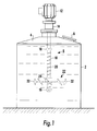
- the illustrated apparatus comprises a conventional liquid container 2 with a lid 4 having a feed inlet 6 for powder.
- a mixing mechanism is indicated generally at 8 and comprises a shaft 10 which extends into the container 2 through a seal in the lid 4, the shaft 10 being driven by a reversible motor 12 through bearings and couplings 14.
- the motor 12 may be electrically or hydraulically powered.
- the shaft 10 carries a pair of stop members 16,18, the stop member 16 being secured to the shaft 10 adjacent the lower end of the shaft 10, and the stop member 18 being secured to the shaft 10 at an intermediate region of the shaft 10.
- a helical projection or rib 20 is provided externally of the shaft 10 between the stop members 16,18 (see in particular Fig. 3), while a mixing disc indicated generally at 22 is mounted on the shaft 10 between the stop members 16,18 (see in particular Figs 4 and 5).
- the disc 22 includes a central hub 24 having a bore 26 through which the shaft 10 freely passes, a helical groove 28 being formed in the internal surface of the hub 24 to extend the length of the hub 24 as indicated in Fig. 6.
- the groove 28 in the hub 24 receives therein the helical projection or rib 20 on the shaft 10 whereby the disc 22 is located on the shaft 10.
- the disc 22 further includes a substantially flat, annular intermediate disc portion 30 from the radially outer regions of which extend a plurality of circumferentially-spaced blades 32.
- Each blade 32 is twisted relative to the disc portion 30 and has an outer edge located at an acute angle to the plane of the disc portion 30, each blade 32 extending symmetrically to each side of the plane of the disc portion 30 as best seen in Fig. 2.
- the described mixing mechanism is positioned within the container 2 as shown in Fig. 1 with the shaft 10 located centrally and vertically and with the stop member 16 within the lower regions of the container 2 and with the stop member 18 within the upper regions of the container 2.
- the apparatus operates as follows.
- the direction of rotation of the shaft 10 is reversed to clockwise as indicated by arrow B in Fig. 5.
- the forces applied to the rotating disc 22 are now such as to urge the disc 22 upwardly within the container 2 as indicated by the arrow C in Fig. 5, the result being that the disc 22 is rotated at a speed greater than that of the shaft 10 and moves upwardly relative to the shaft 10 along the helical rib 20 until it abuts the stop member 18 which determines the limit of upward movement.
- the disc 22 On continued rotation of the shaft 10 in a clockwise direction, the disc 22 is rotated therewith in its upper position to effect mixing within the upper regions of the container 2.
- the co-operating means between the shaft 10 and the disc 22 to ensure relative axial movement therebetween on reverse rotation of the drive to the shaft may be other than helical, for example linear, while the shaft 10 may be positioned other than centrally and vertically within the container 2.
- the rib 20 on the shaft 10 may be discontinuous or intermittent with gaps between adjacent extents of the rib.
- An intermittent helix provides for improved cleaning efficiency and less likelihood of clogging due to product adhesion on the rib 20.
- the shaft 10 may have a helical groove formed therein to extend between the lower and upper stop members 16,18, with a corresponding helical projection being formed on the inner surface of the hub 24 to be received in said groove.
- the apparatus of the invention considerably reduces the overall head height of the assembly, reduces the likelihood of breaking or damaging the seal through which the drive shaft 10 extends thereby reducing potential environmental problems, reduces the overall cost of the equipment, and provides for faster and more efficient mixing than heretofore.
Landscapes
- Chemical & Material Sciences (AREA)
- Chemical Kinetics & Catalysis (AREA)
- Accessories For Mixers (AREA)
- Mixers Of The Rotary Stirring Type (AREA)
Applications Claiming Priority (2)
| Application Number | Priority Date | Filing Date | Title |
|---|---|---|---|
| GBGB9713967.9A GB9713967D0 (en) | 1997-07-03 | 1997-07-03 | Self raising/lowering disperser disc |
| GB9713967 | 1997-07-03 |
Publications (2)
| Publication Number | Publication Date |
|---|---|
| EP0888811A2 true EP0888811A2 (de) | 1999-01-07 |
| EP0888811A3 EP0888811A3 (de) | 2000-11-15 |
Family
ID=10815259
Family Applications (1)
| Application Number | Title | Priority Date | Filing Date |
|---|---|---|---|
| EP98305267A Withdrawn EP0888811A3 (de) | 1997-07-03 | 1998-07-02 | Mischvorrichtung |
Country Status (2)
| Country | Link |
|---|---|
| EP (1) | EP0888811A3 (de) |
| GB (1) | GB9713967D0 (de) |
Cited By (9)
| Publication number | Priority date | Publication date | Assignee | Title |
|---|---|---|---|---|
| EP1264630A3 (de) * | 2001-06-05 | 2003-10-08 | Withdeal Limited | Mischvorrichtung |
| WO2009083141A1 (de) | 2008-01-03 | 2009-07-09 | Umsonst-Kuebler Petra | Vorrichtung zum durchmischen einer masse |
| CN109225011A (zh) * | 2018-08-31 | 2019-01-18 | 福建省大田县恒丰工贸有限公司 | 一种熔炼炉的双层搅拌机构 |
| CN109248615A (zh) * | 2018-11-22 | 2019-01-22 | 东台市高科技术创业园有限公司 | 一种伸缩延长式电子搅拌装置 |
| CN109966978A (zh) * | 2019-03-24 | 2019-07-05 | 柏涛涛 | 用于饲料搅拌的自动化机械设备 |
| CN112095157A (zh) * | 2020-08-13 | 2020-12-18 | 利辛县欣荣针织服饰有限公司 | 一种纤维用原料搅拌装置 |
| CN112844124A (zh) * | 2020-12-30 | 2021-05-28 | 北新集团建材股份有限公司 | 一种具有防出料堵塞功能的混合机 |
| CN117183102A (zh) * | 2023-05-18 | 2023-12-08 | 西安宝鑫自动化设备有限公司 | 一种混凝土生产用粉碎研磨混合一体化装置及方法 |
| CN119971840A (zh) * | 2025-04-16 | 2025-05-13 | 口乐(上海)生物科技有限公司 | 一种牙膏生产用加工设备 |
Family Cites Families (6)
| Publication number | Priority date | Publication date | Assignee | Title |
|---|---|---|---|---|
| DE1161860B (de) * | 1958-10-21 | 1964-01-30 | Maskin Aktiebolaget Plavia | Ruehrwerk zum Aufschlaemmen von schnell absitzenden Suspensionen |
| US3381941A (en) * | 1966-08-17 | 1968-05-07 | Fmc Corp | Stirring apparatus |
| US3907459A (en) * | 1974-08-19 | 1975-09-23 | Arthur R Guedel | Mixing apparatus |
| DE2918997A1 (de) * | 1979-05-11 | 1980-11-20 | Kloeckner Humboldt Deutz Ag | Verfahren und vorrichtung zum ruehren von suspensionen |
| JPS614599A (ja) * | 1984-06-19 | 1986-01-10 | Matsushita Electric Ind Co Ltd | メタン発酵装置 |
| FR2685220A1 (fr) * | 1991-12-19 | 1993-06-25 | Badey Jacques | Procede pour diminuer la puissance absorbee d'un mobile d'agitation et mobile d'agitation en faisant application. |
-
1997
- 1997-07-03 GB GBGB9713967.9A patent/GB9713967D0/en active Pending
-
1998
- 1998-07-02 EP EP98305267A patent/EP0888811A3/de not_active Withdrawn
Cited By (10)
| Publication number | Priority date | Publication date | Assignee | Title |
|---|---|---|---|---|
| EP1264630A3 (de) * | 2001-06-05 | 2003-10-08 | Withdeal Limited | Mischvorrichtung |
| WO2009083141A1 (de) | 2008-01-03 | 2009-07-09 | Umsonst-Kuebler Petra | Vorrichtung zum durchmischen einer masse |
| US8807821B2 (en) | 2008-01-03 | 2014-08-19 | Petra Umsonst-Kübler | Device for mixing a compound in a container |
| CN109225011A (zh) * | 2018-08-31 | 2019-01-18 | 福建省大田县恒丰工贸有限公司 | 一种熔炼炉的双层搅拌机构 |
| CN109248615A (zh) * | 2018-11-22 | 2019-01-22 | 东台市高科技术创业园有限公司 | 一种伸缩延长式电子搅拌装置 |
| CN109966978A (zh) * | 2019-03-24 | 2019-07-05 | 柏涛涛 | 用于饲料搅拌的自动化机械设备 |
| CN112095157A (zh) * | 2020-08-13 | 2020-12-18 | 利辛县欣荣针织服饰有限公司 | 一种纤维用原料搅拌装置 |
| CN112844124A (zh) * | 2020-12-30 | 2021-05-28 | 北新集团建材股份有限公司 | 一种具有防出料堵塞功能的混合机 |
| CN117183102A (zh) * | 2023-05-18 | 2023-12-08 | 西安宝鑫自动化设备有限公司 | 一种混凝土生产用粉碎研磨混合一体化装置及方法 |
| CN119971840A (zh) * | 2025-04-16 | 2025-05-13 | 口乐(上海)生物科技有限公司 | 一种牙膏生产用加工设备 |
Also Published As
| Publication number | Publication date |
|---|---|
| EP0888811A3 (de) | 2000-11-15 |
| GB9713967D0 (en) | 1997-09-10 |
Similar Documents
| Publication | Publication Date | Title |
|---|---|---|
| US8167480B2 (en) | Processing unit | |
| EP0888811A2 (de) | Mischvorrichtung | |
| US5549384A (en) | Mixer with helically extending blades | |
| EP1125625B1 (de) | Homogenisiereinrichtung | |
| KR101611892B1 (ko) | 데드 존이 없는 3개의 블레이드를 구비한 교반장치 | |
| EP0185843A2 (de) | Senkrechte Siebmaschine für körniges Material | |
| US4848919A (en) | Pinned mill for mixers | |
| EP1264630A2 (de) | Mischvorrichtung | |
| CA1134811A (en) | Dual drive co-axial disperser | |
| CA1091210A (en) | Apparatus for dispersing finely divided solid particles in a liquid vehicle | |
| EP0647467B1 (de) | Einheitlicher, einstückiger, drehbarer Mischer und Abgabekopf | |
| JPS61146506A (ja) | コンクリートミキサー | |
| EP1419011A4 (de) | Zerkleinerungsvorrichtung und rotor dafür | |
| US6076754A (en) | Mixer apparatus with improved chopper assembly | |
| KR20010113439A (ko) | 교반장치 | |
| KR200184538Y1 (ko) | 교반장치의 임펠러 | |
| CN109529669B (zh) | 一种带出料功能的涂料搅拌机 | |
| US2867386A (en) | Mixing apparatus | |
| SU1248653A1 (ru) | Устройство дл измельчени и перемешивани материалов | |
| CN219791200U (zh) | 固体料的下料装置 | |
| CN217527065U (zh) | 一种高粘度物料搅拌头及搅拌装置 | |
| CN221674010U (zh) | 一种混合机 | |
| CN115518748B (zh) | 用于载有固体的液体的泵的切割环 | |
| CN210905801U (zh) | 一种色浆高效搅拌分散装置 | |
| JP2001300280A (ja) | 撹拌機 |
Legal Events
| Date | Code | Title | Description |
|---|---|---|---|
| PUAI | Public reference made under article 153(3) epc to a published international application that has entered the european phase |
Free format text: ORIGINAL CODE: 0009012 |
|
| AK | Designated contracting states |
Kind code of ref document: A2 Designated state(s): AT BE CH DE DK ES FI FR GB IE IT LI NL PT SE |
|
| AX | Request for extension of the european patent |
Free format text: AL;LT;LV;MK;RO;SI |
|
| PUAL | Search report despatched |
Free format text: ORIGINAL CODE: 0009013 |
|
| AK | Designated contracting states |
Kind code of ref document: A3 Designated state(s): AT BE CH CY DE DK ES FI FR GB GR IE IT LI LU MC NL PT SE |
|
| AX | Request for extension of the european patent |
Free format text: AL;LT;LV;MK;RO;SI |
|
| 17P | Request for examination filed |
Effective date: 20010417 |
|
| AKX | Designation fees paid |
Free format text: AT BE CH DE DK ES FI FR GB IE IT LI NL PT SE |
|
| 17Q | First examination report despatched |
Effective date: 20020711 |
|
| STAA | Information on the status of an ep patent application or granted ep patent |
Free format text: STATUS: THE APPLICATION IS DEEMED TO BE WITHDRAWN |
|
| 18D | Application deemed to be withdrawn |
Effective date: 20030122 |