EP0888848A1 - Lapp- und Polierkopf für Steinplatte - Google Patents
Lapp- und Polierkopf für Steinplatte Download PDFInfo
- Publication number
- EP0888848A1 EP0888848A1 EP98830366A EP98830366A EP0888848A1 EP 0888848 A1 EP0888848 A1 EP 0888848A1 EP 98830366 A EP98830366 A EP 98830366A EP 98830366 A EP98830366 A EP 98830366A EP 0888848 A1 EP0888848 A1 EP 0888848A1
- Authority
- EP
- European Patent Office
- Prior art keywords
- shaft
- lapping
- shafts
- bowl
- oscillating
- Prior art date
- Legal status (The legal status is an assumption and is not a legal conclusion. Google has not performed a legal analysis and makes no representation as to the accuracy of the status listed.)
- Withdrawn
Links
- 238000005498 polishing Methods 0.000 title claims description 8
- 239000004575 stone Substances 0.000 title claims description 6
- 230000005540 biological transmission Effects 0.000 claims abstract description 6
- 238000007789 sealing Methods 0.000 claims description 2
- 125000006850 spacer group Chemical group 0.000 claims description 2
- 239000000463 material Substances 0.000 description 3
- 239000007900 aqueous suspension Substances 0.000 description 2
- 230000007246 mechanism Effects 0.000 description 2
- 230000002093 peripheral effect Effects 0.000 description 2
- 239000007788 liquid Substances 0.000 description 1
- 238000004519 manufacturing process Methods 0.000 description 1
- 239000004579 marble Substances 0.000 description 1
- 230000010355 oscillation Effects 0.000 description 1
- 239000000843 powder Substances 0.000 description 1
- 230000000717 retained effect Effects 0.000 description 1
- 238000005096 rolling process Methods 0.000 description 1
- 230000003068 static effect Effects 0.000 description 1
- XLYOFNOQVPJJNP-UHFFFAOYSA-N water Substances O XLYOFNOQVPJJNP-UHFFFAOYSA-N 0.000 description 1
Images


Classifications
-
- B—PERFORMING OPERATIONS; TRANSPORTING
- B24—GRINDING; POLISHING
- B24B—MACHINES, DEVICES, OR PROCESSES FOR GRINDING OR POLISHING; DRESSING OR CONDITIONING OF ABRADING SURFACES; FEEDING OF GRINDING, POLISHING, OR LAPPING AGENTS
- B24B41/00—Component parts such as frames, beds, carriages, headstocks
- B24B41/04—Headstocks; Working-spindles; Features relating thereto
- B24B41/047—Grinding heads for working on plane surfaces
- B24B41/0475—Grinding heads for working on plane surfaces equipped with oscillating abrasive blocks, e.g. mounted on a rotating head
Definitions
- lapping machines comprising a rotating head on which there are mounted grinding inserts which are kept in contact with one side of said slabs to be machined, in the presence of a stream of an aqueous suspension of abrasive powder.
- the slab of stone material is moved with respect to the rotating head so that the entire surface of the slab itself is machined.
- the rotating head comprises a rotating bowl-shaped casing for driving by a central shaft by which said bowl is supported by means of resiliently yielding spacers.
- the casing is closed, with the arrangement, in between, of a sealing gasket, by a flanged cover supported by a fixed structure of the machine and defines, together with the cover, a lubricant-tight compartment.
- Shafts are provided in rotational seats of said bowl-shaped casing and are intended to operate in an oscillating manner lapping tools so that the inserts come into contact with the surface to be machined by means of generatrices of a conical surface thereof which are always new.
- the present invention envisages for operation of said shafts: an endless screw coaxial with said central shaft and fixed to said cover; helical gears supported by said bowl and cooperating with said endless screw; an articulated drive between each helical gear and one of said shafts; and means for transmission from said oscillating shaft to other adjacent oscillating shafts.
- the rotating movement of the head generates, in a simple and easily reproducible manner, a relatively very slow oscillating movement of the grinding inserts about an axis parallel to the line of contact with the surface to be machined.
- adjacent inserts oscillate in opposite directions with respect to one another, generating balanced reaction forces and avoiding the occurrence of vibrations.
- Said articulated drive comprises preferably an eccentric cam which is integral with the shaft of each helical gear and a connecting rod with articulated bearings which is arranged between said eccentric cam and a pivot of a bush integral with said shaft.
- said means for transmission from said oscillating shaft may comprise bevel gear portions or equivalent means arranged between said oscillating shaft actuated by said articulated drive and a shaft adjacent thereto, and between the latter and the following one.
- the head may also comprise a moving assembly fixed to a hub formed centrally by said bowl and forming the seats for the shafts of said helical gears. In this way the head is extremely compact and easily assembled and maintained.
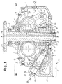
- the lapping head in question for polishing marble or other stone material surfaces comprises a bowl-shaped casing (Fig. 1) which is closed at the top - with the arrangement, in between, of a seal 5 - by a cover 3 in the form of a flange.
- the cover 3 is fixed to the static structure of a grinding machine, not shown, by means of bolts which are screwed into threaded holes 3A of the cover; by means of bearings 7 said cover 3 supports a vertical shaft 9 with an axis X-X which is moved rotationally by means of a flange 9A, an upper joint and a motor drive system, not shown in the drawing.
- the shaft 9 has an axial through-hole 9B through which an abrasive liquid, generally an aqueous suspension of abrasive, is supplied to the surface to be lapped.
- the bowl-shaped casing 1 is supported by the shaft 9 by means of a disk-shaped flange 11 which is keyed and fixed axially to the shaft 9 in the vicinity of the bottom end thereof.
- the radially projecting part of the flange 11 is axially clamped - by means of a plate 15, special screws not shown and via two resilient rings 13 - inside a cylindrical recess formed in a bottom central hub 1B of the bowl-shaped casing 1, this recess being delimited at the top by an abutment surface 1A.
- the flange 11 has a peripheral surface of spherical shape, this surface being combined with a small amount of play with the internal cylindrical surface of said recess; in this way the bowl-shaped casing 1 is centred with respect to the axis X-X and, owing to the presence of the two resilient rings 13, small angular oscillations of the casing itself are permitted.
- the plate 15 there are formed blind holes each receiving - with a minimum amount of play - the head of a respective bolt 17 screwed into a hole of an end flange 19.
- Said flange 19 is keyed onto the shaft 9 by means of a splined section 9D and is axially clamped onto the shaft 9 by means of a screw-type ring 21. In this way, with the rotation of the shaft 9, the casing 1 is moved rotationally with respect to the cover 3 by means of the heads of the bolts 17.
- the bottom recess of the casing 1 is closed by a cover 23 by means of peripheral clamping screws - not shown - with the arrangement, in between, of seals 25, 27 so as to prevent the entry of water and abrasive inside the casing itself.
- Each shaft 33 is retained axially - via screws not shown - by means of a respective flange 35 which is fixed to the side surface of the casing 1; a seal 37 is arranged between the flange 35 and the respective shaft 33.
- Each shaft 33 projects externally from said casing 1 with a splined shank 33A on which one end of a right-angled arm 39 carrying a lapping tool 41 is mounted; each tool is provided with a frusto-conical working surface 41A with an axis Y-Y, so as to act on a plane perpendicular to the axis X-X of rotation of the lapping head.
- a bolt 43 which is screwed into an axial end hole of the shaft 33, is tightened against the arm 39 with the arrangement, in between, of a washer 44 and ensures that there is no loosening of the right-angled arm 39 with the associated shaft 33.
- a disk 45 extending at the bottom into a coaxial sleeve 45A is fixed - by means of screws not shown - underneath the cover 3 of the lapping head.
- the sleeve is fitted rotatably with a minimum amount of play onto the shaft 9 and has externally an endless screw 45B.
- the upper surface of the hub 1B has, fixed to it, a moving assembly 46 comprising a plate 47 (see Figs. 1 and 2) on which two supports 49 are formed on opposite sides of the axis X-X; each of said supports 49 carries, by means of rolling bearings 51, 53, a respective rotating shaft 55; the axes of the two shafts 55 are parallel and lie in a plane perpendicular to the axis X-X.
- a respective helical gear wheel 57 meshing with said endless screw 45B is keyed onto each shaft 55.
- each shaft 55 has a seat 55A which is eccentric with respect to said bearings and to which one end of a respective connecting rod 61 is rotatably coupled via a spherical bearing 59.
- each of these two connecting rods 61 is rotatably coupled, by means of another spherical bearing 63 (see also Fig. 4), with a pivot 65 radially integral with a bush 67 keyed by means of a splined profile 67A onto one 33A of said inclined shafts 33 associated with the locations A, D.
- the moving assembly 46 rotates integrally therewith and the gear wheels 57, meshing with the endless screw 45B of the sleeve 45A fixed to the structure of the machine, rotate slowly with respect to the rotating movement of the head in accordance with the transmission ratio of the endless screw 45B and the two wheels 57 themselves; the latter in turn cause the respective lapping tool 41 to oscillate about the respective axis Y-Y, by means of the crank mechanism 55A, 59, 61, 63, 65, 67.
- the moving assembly 46 thus actuates directly the tools 41 associated with the diametrically opposite locations A, D, causing them to oscillate.
- the tools 41 corresponding to the other shafts 33 of the following stations B, C; E, F, in the direction of the arrow F of Fig. 3, receive a similar oscillating movement from the shafts 33 of the locations A; D by means of bevel gear portions 69, 71, 75, 77 (see Figs. 4, 5) fixed to respective bushes 67, 73, 79 each keyed to the respective shaft 33, the bush 67 being integral with the pivot 65.
- each tool 41 during rotation of the lapping head, oscillates about the respective axis Y-Y, constantly offering a different and always new line of contact with the surface to be machined.
- adjacent tools oscillate in opposite directions transmitting to the lapping head balanced forces so as to avoid the generation of vibrations which could damage the head and result in poor quality lapping.
Landscapes
- Engineering & Computer Science (AREA)
- Mechanical Engineering (AREA)
- Finish Polishing, Edge Sharpening, And Grinding By Specific Grinding Devices (AREA)
Applications Claiming Priority (2)
| Application Number | Priority Date | Filing Date | Title |
|---|---|---|---|
| IT97FI000145A IT1293124B1 (it) | 1997-06-18 | 1997-06-18 | Testa levigatrice e lucidatrice per lastre lapidee |
| ITFI970145 | 1997-06-18 |
Publications (1)
| Publication Number | Publication Date |
|---|---|
| EP0888848A1 true EP0888848A1 (de) | 1999-01-07 |
Family
ID=11352161
Family Applications (1)
| Application Number | Title | Priority Date | Filing Date |
|---|---|---|---|
| EP98830366A Withdrawn EP0888848A1 (de) | 1997-06-18 | 1998-06-16 | Lapp- und Polierkopf für Steinplatte |
Country Status (2)
| Country | Link |
|---|---|
| EP (1) | EP0888848A1 (de) |
| IT (1) | IT1293124B1 (de) |
Cited By (4)
| Publication number | Priority date | Publication date | Assignee | Title |
|---|---|---|---|---|
| RU2172236C2 (ru) * | 1999-03-12 | 2001-08-20 | Акционерное общество открытого типа "Коростышевский карьер" | Головка тангенциальная шлифовальная (варианты) |
| ITFI20120227A1 (it) * | 2012-10-25 | 2014-04-26 | Comes Srl | Carter di contenimento per teste portautensili |
| CN108673336A (zh) * | 2018-07-18 | 2018-10-19 | 窦业正 | 一种打磨机用磨头 |
| CN114102428A (zh) * | 2021-12-15 | 2022-03-01 | 佛山市纳德新材料科技有限公司 | 一种抛光机用磨头 |
Citations (4)
| Publication number | Priority date | Publication date | Assignee | Title |
|---|---|---|---|---|
| EP0448847A1 (de) * | 1990-03-17 | 1991-10-02 | Officine Meccaniche F.Lli Zambon S.N.C. | Rotierender Schleifkopf mit schwingenden Schleifsteinen zum Planieren und Polieren von Oberflächen aus Granit, Keramik oder Marmor |
| EP0510603A2 (de) * | 1991-04-23 | 1992-10-28 | Simec S.P.A. | Schleifkopf, insbesondere zum Schleifen von Marmor, Granit und Gestein im allgemeinen |
| EP0649706A1 (de) * | 1993-09-22 | 1995-04-26 | Luca Toncelli | Ein Lapp- und Polierkopf für Granit und ähnliches Gestein |
| DE4408560A1 (de) * | 1994-03-14 | 1995-09-21 | Ralf Schankweiler | Vorrichtung zur Oberflächenbearbeitung von Natur- oder Kunststein |
-
1997
- 1997-06-18 IT IT97FI000145A patent/IT1293124B1/it active IP Right Grant
-
1998
- 1998-06-16 EP EP98830366A patent/EP0888848A1/de not_active Withdrawn
Patent Citations (4)
| Publication number | Priority date | Publication date | Assignee | Title |
|---|---|---|---|---|
| EP0448847A1 (de) * | 1990-03-17 | 1991-10-02 | Officine Meccaniche F.Lli Zambon S.N.C. | Rotierender Schleifkopf mit schwingenden Schleifsteinen zum Planieren und Polieren von Oberflächen aus Granit, Keramik oder Marmor |
| EP0510603A2 (de) * | 1991-04-23 | 1992-10-28 | Simec S.P.A. | Schleifkopf, insbesondere zum Schleifen von Marmor, Granit und Gestein im allgemeinen |
| EP0649706A1 (de) * | 1993-09-22 | 1995-04-26 | Luca Toncelli | Ein Lapp- und Polierkopf für Granit und ähnliches Gestein |
| DE4408560A1 (de) * | 1994-03-14 | 1995-09-21 | Ralf Schankweiler | Vorrichtung zur Oberflächenbearbeitung von Natur- oder Kunststein |
Cited By (4)
| Publication number | Priority date | Publication date | Assignee | Title |
|---|---|---|---|---|
| RU2172236C2 (ru) * | 1999-03-12 | 2001-08-20 | Акционерное общество открытого типа "Коростышевский карьер" | Головка тангенциальная шлифовальная (варианты) |
| ITFI20120227A1 (it) * | 2012-10-25 | 2014-04-26 | Comes Srl | Carter di contenimento per teste portautensili |
| CN108673336A (zh) * | 2018-07-18 | 2018-10-19 | 窦业正 | 一种打磨机用磨头 |
| CN114102428A (zh) * | 2021-12-15 | 2022-03-01 | 佛山市纳德新材料科技有限公司 | 一种抛光机用磨头 |
Also Published As
| Publication number | Publication date |
|---|---|
| IT1293124B1 (it) | 1999-02-11 |
| ITFI970145A1 (it) | 1998-12-18 |
| ITFI970145A0 (it) | 1997-06-18 |
Similar Documents
| Publication | Publication Date | Title |
|---|---|---|
| CA1259604A (en) | Motor driven tool | |
| EP0888848A1 (de) | Lapp- und Polierkopf für Steinplatte | |
| US4615145A (en) | Apparatus for mechanically finishing workpieces | |
| EP0437831B1 (de) | Polierkopf mit schwingenden Schleifsteinen zum Bearbeiten von Steinmaterialien, insbesondere von Granitplatten | |
| JP2002254278A (ja) | 接合面の加工方法及び装置 | |
| EP0371038A1 (de) | Gyro-mahlvorrichtung. | |
| JPH0725018B2 (ja) | 石材用研磨ヘッド | |
| EP3856458B1 (de) | Betätigungskopf mit elektrospindeln | |
| KR860008002A (ko) | 통상 또는 주상물(株狀物)의 외주면 연마방법 및 장치 | |
| WO2009090551A1 (en) | 'head for the treatment of stone and ceramic material | |
| KR20040025080A (ko) | 음극선관용 유리 연마장치의 연마툴 | |
| JPH0413076Y2 (de) | ||
| CN108637874B (zh) | 三自由度球体自转式研抛装置 | |
| JP2001286746A (ja) | 同心2軸竪型攪拌機の駆動部構造 | |
| KR100248873B1 (ko) | 브라운관 연마장치 | |
| KR100407731B1 (ko) | 진동 및 회전 공구홀더를 포함한 랩핑 헤드 | |
| KR19990035444U (ko) | 각도변환추를부착하는진동바렐연마기용진동정역모터 | |
| JP3081293B2 (ja) | 転走面超仕上加工機における砥石揺動装置 | |
| SU757308A1 (ru) | Устройство для доводки плоских поверхностей деталей 1 | |
| EP0974424A1 (de) | Läppkopf | |
| ITFI950066A1 (it) | Testa perfezionata per macchine lucidatrici con bracci portasettori oscillanti | |
| SU1207735A1 (ru) | Устройство дл сообщени осциллирующего движени шпинделю станка | |
| JPH02212064A (ja) | フライス盤の主軸ハウジングに装着するための加工装置 | |
| US1989905A (en) | Valve seat grinding machine | |
| SU1421510A1 (ru) | Абразивный инструмент |
Legal Events
| Date | Code | Title | Description |
|---|---|---|---|
| PUAI | Public reference made under article 153(3) epc to a published international application that has entered the european phase |
Free format text: ORIGINAL CODE: 0009012 |
|
| AK | Designated contracting states |
Kind code of ref document: A1 Designated state(s): DE ES FR GB GR IT PT |
|
| AX | Request for extension of the european patent |
Free format text: AL;LT;LV;MK;RO;SI |
|
| 17P | Request for examination filed |
Effective date: 19990323 |
|
| AKX | Designation fees paid |
Free format text: DE ES FR GB GR IT PT |
|
| 17Q | First examination report despatched |
Effective date: 20010307 |
|
| STAA | Information on the status of an ep patent application or granted ep patent |
Free format text: STATUS: THE APPLICATION IS DEEMED TO BE WITHDRAWN |
|
| 18D | Application deemed to be withdrawn |
Effective date: 20010718 |