EP0888896A1 - Machine et procédé pour imprimer au pochoir - Google Patents
Machine et procédé pour imprimer au pochoir Download PDFInfo
- Publication number
- EP0888896A1 EP0888896A1 EP98112077A EP98112077A EP0888896A1 EP 0888896 A1 EP0888896 A1 EP 0888896A1 EP 98112077 A EP98112077 A EP 98112077A EP 98112077 A EP98112077 A EP 98112077A EP 0888896 A1 EP0888896 A1 EP 0888896A1
- Authority
- EP
- European Patent Office
- Prior art keywords
- printing
- area
- image
- matrix
- sheet
- Prior art date
- Legal status (The legal status is an assumption and is not a legal conclusion. Google has not performed a legal analysis and makes no representation as to the accuracy of the status listed.)
- Granted
Links
Images


Classifications
-
- B—PERFORMING OPERATIONS; TRANSPORTING
- B41—PRINTING; LINING MACHINES; TYPEWRITERS; STAMPS
- B41L—APPARATUS OR DEVICES FOR MANIFOLDING, DUPLICATING OR PRINTING FOR OFFICE OR OTHER COMMERCIAL PURPOSES; ADDRESSING MACHINES OR LIKE SERIES-PRINTING MACHINES
- B41L13/00—Stencilling apparatus for office or other commercial use
- B41L13/04—Stencilling apparatus for office or other commercial use with curved or rotary stencil carriers
- B41L13/06—Stencilling apparatus for office or other commercial use with curved or rotary stencil carriers with a single cylinder carrying the stencil
Definitions
- This invention relates to a stencil printer and a method of stencil printing in which the printing matrix area formed on a stencil is determined depending on the size of printing papers.
- a stencil printer there has been known one comprising a cylindrical drum having a porous circumferential wall on which a stencil is mounted, an ink supply section which supplies the inner surface of the circumferential wall with ink, and a pressure roller which is disposed in parallel to the drum at a predetermined distance therefrom. Sheets of paper are supplied between the cylindrical drum and the pressure roller from a sheet feed section when printing.
- a stencil having a printing matrix area corresponding to the A3 size is mounted on the drum
- the printing matrix area projects outward beyond the edges of the printing paper and ink passing through the stencil in the projecting portions of the printing matrix area is transferred to the pressure roller to stain the surface of the pressure roller.
- the ink on the pressure roller is transferred to the back side of the printing paper, which results in contamination of the printed papers.
- each drum is used for one color only, for instance, one for black, one for red, one for blue and so on. Accordingly when the printing color is to be changed, the drum is replaced.
- a stencil printer A prints on A3 size sheets with a drum for black while a stencil printer B prints on A4 size sheets with a drum for red. Then it is further assumed that necessity of changing the printing color from red to black without changing the printing size (A4) arises in the stencil printer B.
- black ink is supplied over an area of the drum surface corresponding to the printing matrix area of the A3 size sheets which is larger than the A4 size sheets and the black ink supplied in the portion outside the A4 size sheets is transferred to the pressure roller.
- a similar problem arises when the printing size is reduced to a size smaller than A3 in the stencil printer A.
- the primary object of the present invention is to provide a stencil printer and a method of stencil printing in which contamination with ink of the pressing part which is pressed against the printing drum during printing is prevented.
- Another object of the present invention is to provide a stencil printer and a method of stencil printing in which the entire image on the printing matrix area can be printed on the printing paper without a part of the image being cut, whereby a desired printing can be obtained according to the printing matrix area.
- a stencil printer comprising an image recording section which thermally makes a printing matrix on a stencil on the basis of image information representing an image on an original, a printing drum around which the stencil is wrapped, a paper feed section which supports a printing paper sheet stack and feeds the sheets in the stack toward the printing drum, and a pressure member which is opposed to the printing drum and presses the sheet against the printing drum, the sheet size of the printing paper sheets supported by the paper feed section being detected by a sheet size sensor provided on the paper feed section and the area of the printing matrix to be made by the image recording section being determined according to the sheet size, wherein the improvement comprises
- a stencil printer comprising an image read-out section which optically reads out an image on an original, an image recording section which thermally makes a printing matrix on a stencil on the basis of image information representing the image on the original read out by the image read-out section, a printing drum around which the stencil is wrapped, a paper feed section which supports a printing paper sheet stack and feeds the sheets in the stack toward the printing drum, and a pressure member which is opposed to the printing drum and presses the sheet against the printing drum, the sheet size of the printing paper sheets supported by the paper feed section being detected by a sheet size sensor provided on the paper feed section and the area of the printing matrix to be made by the image recording section being determined according to the sheet size, wherein the improvement comprises
- a stencil printer comprising an image read-out section which optically reads out an image on an original, an image recording section which thermally makes a printing matrix on a stencil on the basis of image information representing the image on the original read out by the image read-out section, a printing drum around which the stencil is wrapped, a paper feed section which supports a printing paper sheet stack and feeds the sheets in the stack toward the printing drum, and a pressure member which is opposed to the printing drum and presses the sheet against the printing drum, the sheet size of the printing paper sheets supported by the paper feed section being detected by a sheet size sensor provided on the paper feed section and the area of the printing matrix to be made by the image recording section being determined according to the sheet size, wherein the improvement comprises
- an alarm means which alarms that the image on the original is not correctly represented by the printing matrix when the printing area is smaller than the image area on the original and the area of the printing matrix is determined to be equal to the printing area.
- a stencil printer comprising an image read-out section which optically reads out an image on an original, an original detecting means which is provided in the image read-out section and detects the size of the original, an image recording section which thermally makes a printing matrix on a stencil on the basis of image information representing the image on the original read out by the image read-out section, a printing drum around which the stencil is wrapped, a paper feed section which supports a printing paper sheet stack and feeds the sheets in the stack toward the printing drum, and a pressure member which is opposed to the printing drum and presses the sheet against the printing drum, the sheet size of the printing paper sheets supported by the paper feed section being detected by a sheet size sensor provided on the paper feed section and the area of the printing matrix to be made by the image recording section being determined according to the sheet size, wherein the improvement comprises
- an alarm means which alarms that the image on the original is not correctly represented by the printing matrix when the sheet size is smaller than the size of the original and the area of the printing matrix is determined to be equal to the sheet size.
- a method of stencil printing wherein a printing matrix is thermally made in a printing matrix area on a stencil material on the basis of image information representing an image on an original, the printing matrix area being determined according the sheet size of printing paper sheet, the stencil thus obtained is wrapped around a printing drum, and a printing paper sheet fed toward the printing drum is pressed against the printing drum by a pressure member, wherein the improvement comprises the steps of
- a method of stencil printing wherein a printing matrix is thermally made in a printing matrix area on a stencil material on the basis of image information representing an image on an original, the printing matrix area being determined according the sheet size of printing paper sheet, the stencil thus obtained is wrapped around a printing drum, and a printing paper sheet fed toward the printing drum is pressed against the printing drum by a pressure member, wherein the improvement comprises the steps of
- a seventh aspect of the present invention there is provided a method of stencil printing wherein a printing matrix is thermally made in a printing matrix area on a stencil material on the basis of image information representing an image on an original, the printing matrix area being determined according the sheet size of printing paper sheet, the stencil thus obtained is wrapped around a printing drum, and a printing paper sheet fed toward the printing drum is pressed against the printing drum by a pressure member, wherein the improvement comprises the steps of
- a method of stencil printing wherein a printing matrix is thermally made in a printing matrix area on a stencil material on the basis of image information representing an image on an original, the printing matrix area being determined according the sheet size of printing paper sheet, the stencil thus obtained is wrapped around a printing drum, and a printing paper sheet fed toward the printing drum is pressed against the printing drum by a pressure member, wherein the improvement comprises the steps of
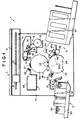
- a stencil printer 1 in accordance with an embodiment of the present invention, comprises an image read-out section 2, an image recording section 3, a printing section 4, a paper feed section 5, a paper discharge section 6 and a stencil discharge section 7.
- the image read-out section 2 comprises an image scanner 9 which is disposed to cover the entire width (the dimension in a main scanning direction) of an original placed on a glass platen 8 with its image side facing the platen 8.
- the image scanner 9 comprises an optical system formed by a light source, mirrors, lenses and the like and a CCD sensor, and is supported by a guide bar 10 to be driven by an electric motor (not shown) by way of an endless belt 11.
- the image scanner 9 is moved along the guide bar 10 in the longitudinal direction of the original (a sub-scanning direction) when the electric motor is energized to drive the endless belt 11 under the control of a CPU 51 of a control system 50 to be described later, and reads out the image on the original line by line.
- the image scanner 9 inputs the image information thus obtained into the CPU 51 of the control system 50.
- the image read-out section 2 is provided with an original size detecting means 12 (Figure 3).
- the original size detecting means 12 may comprise a plurality of reflective sensors disposed opposed to the glass platen 8 in positions corresponding to regular original sizes.
- the original size detecting means 12 detects the size of the original placed on the platen 8 and inputs a detecting signal representing the size of the original into the CPU 51 of the control system 50.
- the image recording section 3 comprises a roll 13 of a stencil material in a continuous length, a thermal heat 14, a platen roller 15, a roll feed roller 16, a guide roller 17 and a cutter 18.
- the thermal head 14 comprises an array of a plurality of point heaters. Each time the image read-out section 2 reads out image data for one line of the original, the line data is transferred to the thermal head 14 by way of the CPU 51 of the control system 50.
- the point heaters of the thermal head 14 are selectively caused to generate heat on the basis of the line data transferred from the image read-out section 2.
- the stencil material is heat-sensitive and the image information is thus thermally recorded on the stencil material in a dot matrix over a printing matrix area determined by the control system 50. Then the thus formed stencil is cut away from the stencil material roll 13 by the cutter 18.
- the printing section 4 comprises a drum 19 and a pressure roller 20.
- the drum 19 is cylindrical and is formed of a material permeable to ink such as a flexible mesh material.
- the stencil is wrapped around the drum 19 and is clamped by a clamp 21.
- An inner pressure roller 22 is disposed inside the drum 19 to be opposed to the pressure roller 20.
- the longitudinal axis of the inner pressure roller 22 is parallel to the generatrix of the drum 19 and the inner pressure roller 22 is in contact with the inner surface 19a of the drum 19.
- a predetermined amount of ink is supplied to the inner surface 19a of the drum 19 by way of the circumferential surface of the inner pressure roller 22 by an ink supply system (not shown).
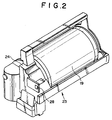
- the drum 19 is supported for rotation on a frame 24 of a unitized support system 23.
- the support system 23 can be drawn out from the printer body 1a so that it can be replaced.
- a drum sensor 25 detects whether the drum 19 is on the printer body 1a.
- the drum sensor 25 may comprise a transmission type optical sensor formed by a light emission sensor and a light reception sensor and a light-shielding plate on the support system 23.
- a transmission type optical sensor formed by a light emission sensor and a light reception sensor and a light-shielding plate on the support system 23.
- the drum sensor 25 may comprise a microswitch which is turned on by a projection on the support system 23 when the support system 23 is properly set to the printer body 1a.
- the support system 23 is provided with a printing matrix size information storage means 28.
- the printing matrix size information storage means 28 may comprise, for instance, a RAM, EEPROM, flash memory or the like and stores information on the printing matrix size.
- the storage means 28 is electrically connected with the CPU 51 of the control system 50 by way of the connectors 26 and 27 to enable read out and write of printing matrix size information when the support system 23 is properly set to the printer body 1a.
- the pressure roller 20 is substantially the same as the printing drum 19 in diameter and is disposed below the drum 19.
- the pressure roller 20 is disposed in parallel to the drum 19 with its circumferential surface spaced from that of the drum 19 by a predetermined distance.
- the pressure roller 20 is rotated about its longitudinal axis 20a in the clockwise direction in Figure 1 at the same speed as the drum 19 in synchronization therewith by a synchronized drive system (not shown).
- a recess 29 is formed on the circumferential surface of the pressure roller 20 and receives the clamp 21 on the drum 19 when the clamp 21 comes to be in contact with the pressure roller 20, thereby preventing the clamp 21 from interfering with the pressure roller 20.
- the pressure roller 20 holds the leading end of a printing paper sheet 34 fed from the paper feed section 5 at a paper take-up position a with its clamp means (not shown) and causes the clamp means to release the paper sheet 34 at a paper release portion b .
- the paper feed section 5 is disposed on the left side below the printing section 4 as shown in Figure 1.
- the paper feed section 5 comprises a paper feed table 30, a pair of paper feed rollers 31, a paper separation roller 32 and a pair of paper supply rollers 33.
- the paper feed table 30 is moved upward by an up-and-down mechanism (not shown) to a predetermined position relative to the paper feed rollers 31 where the uppermost printing paper sheet 34 in the stack on the paper feed table 30 is in contact with the paper feed rollers 31.
- the paper feed rollers 31 and the paper separation roller 32 separates the uppermost paper sheet 34 from the stack and the paper supply rollers 33 supplies the printing paper sheet 34 to the paper take-up position a of the pressure roller 20 at a predetermined timing.
- the paper feed table 30 is provided with a pair of side fences 35 and 36, as shown in Figure 3, which are disposed on opposite sides of the path of feed of the printing paper sheet 34 to be movable in perpendicular to the center line 37 of the path in order to define the positions of the side edges of the sheet 34.
- the side fences 35 and 36 are respectively provided with racks 38 and 39 which are in mesh with a pinion 40 mounted on the paper feed table 30 to be rotatable about a point of the center line 37.
- a sheet width sensor 41 is connected to the pinion 40.
- the sheet width sensor 41 may comprise, for instance, a potentiometer in which a value of a resistor is changed in response to rotation of the pinion 40 and the electric current flowing through the potentiometer changes.
- the value of the electric current output from the sheet width sensor 41 is converted to information on the amount of movement of the side fences 35 and 36 and is input into the CPU 51 of the control system 50.
- a sheet length sensor 42 is disposed in the rear end portion of the paper feed table 30.
- the sheet length sensor 42 may comprise, for instance, a reflective optical sensor.
- the sheet length sensor 42 outputs a detection signal to the CPU 51 when a printing paper sheet 34 covers the detecting surface thereof and a non-detection signal when no sheet covers the same.
- a sheet sensor 43 is disposed in the front end portion of the paper feed table 30.
- the sheet sensor 43 may comprise, for instance, a reflective optical sensor.
- the sheet sensor 43 outputs a signal representing that there exist sheets to the CPU 51 when a printing paper sheet 34 covers the detecting surface thereof and a signal representing that there exists no sheet when no sheet covers the same.
- the paper discharge section 6 is disposed on the right side below the printing section 4 in Figure 1.
- the paper discharge section comprises a pair of pinch rollers 44 (44a and 44b), a discharge claw 45, a discharge roller 46 and a paper discharge table 47.
- One 44a of the pinch rollers is in contact with the pressure roller 20 and the other 44b is in contact with the discharge roller 46.
- the pinch rollers 44 are disposed near the paper release portion b and are associated with the pressure roller 20 to convey the sheet 34.
- the discharge claw 45 separates the printed sheet 34 from the pressure roller 20.
- the discharge roller 46 pinches together with the pinch roller 44b the printed sheet 34 separated from the pressure roller 20 to convey it to the sheet discharge table 47.
- the printed sheets 34 thus discharged are stacked on the sheet discharge table 47.
- the stencil discharge section 7 is disposed on the left side above the printing section 4 in Figure 1.
- the stencil discharge section 7 comprises a pair of stencil discharge rollers 49 which peel the stencil from the drum 19 and convey it into a discharged stencil box 48.
- FIG 3 shows the control system 50 which controls the respective sections of the stencil printer 1 including the paper feed section 5.
- control system 50 comprises a one-chip microcomputer provided with a CPU 51 (a control means such as a micro processor), a ROM 52 (a storage means), and a RAM 53.
- CPU 51 a control means such as a micro processor
- ROM 52 a storage means
- RAM 53 a random access memory
- the CPU 51 controls start and stop of printing operation on the basis of operation of a start key and a stop key on a control panel 54.
- the CPU 51 detects the image area on the original on the basis of image data input from the image read-out section 2.
- the CPU 51 determines the size of the printing paper sheet 34 as shown in the following table 1 on the basis of information on the width of the sheet 34 from the sheet width sensor 41 and information on whether the paper exists from the sheet length sensor 42. For example, when the information from the sheet width sensor 41 indicates that the width of the sheet 34 is 302 to 292mm and the information from the sheet length sensor 42 indicates that a sheet 34 exists over the detecting surface thereof, the CPU 51 determines that the sheet size is A3 and is positioned lengthwise. width information (mm) length sensor signal sheet size 302 to 292 exist A3 lengthwise not exist A4 sidewise 262 to 252 exist B4 lengthwise 215 to 205 not exist A4 lengthwise 187 to 177 not exist B5 lengthwise 105 to 95 not exist postcard
- the CPU 51 determines whether another sheet stack has been placed on the paper feed table on the basis of the signal from the sheet sensor 43. That is, when a signal representing that there exists no sheet is input after input of a signal representing that there exist sheets and then a signal representing that there exist sheets is subsequently input, the CPU 51 determines that another sheet stack has been placed on the paper feed table.
- the CPU 51 determines whether removal and mounting of the support system 23 occurred on the basis of a signal input from the drum sensor 25. Specifically the CPU determines that the drum 19 has been mounted on the printer body 1a when the support system 23 is properly set to the printer body 1a and a drum mount signal is input from the drum sensor 25 by way of the connectors 26 and 27. When no drum mount signal is input, the CPU 51 determines that no drum is on the printer body 1a.
- the CPU 51 transfers image data for each line from the image read-out section 2 to the image recording section 3.
- the CPU 51 reads out and writes printing matrix size information from and in the drum side printing matrix size information storage means 28.
- An error alarm 55 is connected to the CPU 51.
- the error alarm 55 makes a display to the effect that there is fear that the pressure roller 20 can be stained with ink when the CPU 51 determines that the printing area on the printing paper sheet 34 is not larger than the printing matrix area on the stencil. Further when an alarm switch in the CPU 51 is turned on in the printing matrix size determination processing to be described later, the error alarm 55 makes a display to the effect that there is fear that a part of the printing matrix area is cut on the printed image.
- the ROM 52 stores a processing program required for the CPU 51 to execute a series of processing, sheet size information for determining the size of the printing paper sheet, and data such as information on the margin for determining the printing area of the printing paper sheet 34.
- the RAM 53 stores data obtained by processing by the CPU 51, the image data on the original, information on the size of the original, information on the image area on the original, information on the size of the printing paper sheet, information on the printing area on the printing paper sheet, information on the size of the printing matrix area on the stencil, and the like.
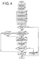
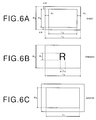
- An original is placed in the image read-out section 2 and the image scanner 9 is moved (pre-scan) on the original in the direction of sub-scanning (longitudinal direction of the original), thereby reading out the image on the original line by line and at the same time detecting the image area (W1 in width and L1 in length, Figure 6B) on the original (S10).
- the image area may be detected in various known manners. A technique for detecting the image area is disclosed in United States Patent No. 4,763,200 for Nakatani et al.
- the sheet size of the printing paper sheet 34 is detected on the basis of information on the width of the sheet 34 from the sheet width sensor 41 and information on whether the paper exists from the sheet length sensor 42 (S20).
- processing for determining the size of the printing matrix area on the stencil is performed (S100).
- the printing area on the sheet 34 is first determined (S101 in Figure 5).
- the printing area is determined on the basis of the sheet size detected in S20 taking into account the margin (S101).
- margin ⁇ W is taken on each end portion of the sheet 34 and margin ⁇ L is taken on each edge portion of the same, whereby the width W3 and the length L3 of the printing area are determined.
- the width W3 of the printing area is compared with the width W1 of the image area of the original (S102).
- the width W4 of the printing matrix area is determined to be the width W3 of the printing area and the alarm switch in the CPU 51 is turned on (S103).
- the width W4 of the printing matrix area is determined to be the width W1 of the image area on the original (S104).
- the length L3 of the printing area is compared with the length L1 of the image area of the original (S105).
- the length L4 of the printing matrix area is determined to be the length L3 of the printing area and the alarm switch in the CPU 51 is turned on (S106).
- the length L4 of the printing matrix area is determined to be the length L1 of the image area on the original (S107).
- the printing matrix area size information thus determined (W4 in width and L4 in length) is transferred to the drum side printing matrix size information storage means 28 (S200).
- image recording is effected while effecting image read-out (S210). That is, in S210, the image scanner 9 in the image read-out section 2 is moved on the original in the sub-scanning direction to read out the image on the original line by line and the image data obtained is transferred to the image recording section 3 to drive the thermal head 14 according to the image data, thereby thermally recording the image on the stencil material as a pattern of perforations over the printing matrix area determined.
- the imagewise perforated stencil is mounted on the drum 19 (S220). That is, the leading end of the stencil is held by the clamp 21 and the stencil is wrapped around the drum 19 in response to rotation of the drum 19.
- the printing area (W3 in width and L3 in length) is determined on the basis of the sheet size of the printing paper sheets 34 detected (S270).
- the printing area determined is not smaller than the printing matrix area (W4 in width and L4 in length in Figure 6C) in both width and length (S280 : YES), printing is performed (S300).
- the paper feed section 5 supplies the sheets 34 one by one.
- the leading end of the sheet 34 is held by the clamp means of the pressure roller 20 and is fed between the pressure roller 20 and the drum 19 in response to rotation of the pressure roller 20.
- the drum 19 is rotated in synchronization with the pressure roller 20 and the sheet 34 is conveyed pinched therebetween.
- the inner pressure roller 22 is rotated in synchronization with the drum 19 and the pressure roller 20 and bulges outward the circumferential wall of the drum 19 and the sheet 34 is sandwiched between the bulged circumferential wall of the drum 19 and the pressure roller 20, and ink supplied on the inner surface of circumferential wall of the drum 19 is transferred to the sheet 34 through the perforations in the printing matrix area on the stencil, whereby an image is recorded on the sheet 34 in a predetermined color.
- the error alarm 55 makes a display to the effect that there is fear that the pressure roller 20 can be stained with ink (S290).
- the printing area is determined to be W2 ( Figure 6A) x L2 ( Figure 6A) in S101. Then the following steps in the flow shown in Figure 5 are performed employing W2 and L2 as the width and the length of the printing area in place of W3 and L3, whereby printing is carried out over the entire area of the sheet 34 according the printing matrix area.
- the size of the original (W5xL5) is detected on the basis of information from the original size detecting means 12, and the flow in Figure 5 is executed employing the width of the original W5 and the length L5 of the original are used in place of the width W1 and the length L1 of the printing matrix area.
- the pressure roller 20 which is pressed against the drum 19 can be surely prevented from being stained with ink. Further when the size of the printing paper sheet 34 is smaller than the size of the printing matrix area, printing is inhibited and a message to the effect that printing cannot be effected is displayed to alarm the operator. Further the printing matrix area is determined taking into account the margin to be provided on the sheet 34, and when the printing area, the area corresponding to the sheet size minus the margin, is smaller than the printing matrix area, printing is inhibited and a message to the effect that printing cannot be effected is displayed to alarm the operator.
- the printing matrix area is determined on the basis of comparison of the image area on the original with the printing area on the printing paper sheet 34 determined taking into account the margin, and when the printing area is smaller than the image area, alarm that the image on the original cannot be wholly recorded on the printing matrix area if the printing matrix area is equal to the printing area is made, a desired printing can be obtained according to the printing matrix area without a part of the image being cut.
- the printing matrix area is set to be the sheet size as a result of determining the printing matrix area on the basis of comparison of the size of the original with the size of the printing paper sheet 34 (i.e., when the printing matrix area determined is smaller than the size of the original), alarm that the image on the original cannot be wholly recorded on the printing matrix area. Accordingly a desired printing can be obtained according to the printing matrix area without a part of the image being cut.
- printing matrix area is determined on the basis of comparison of the size of the original with the size of the printing paper sheet 34, printing is carried out over the entire area of the sheet 34 according the printing matrix area.
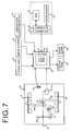
- the length of the sheets 34 on the paper feed table 34 is detected by the sheet length sensor 42 which is a reflective optical sensor, the length of the sheets 34 mat be detected by an arrangement shown in Figure 7.
- the components analogous to those shown in Figure 3 are given the same reference numerals and will not be described here.
- the paper feed table 30 is provided with an end fence 60 which defines the position of the trailing end of the sheets 34 on the feed table 30.
- the end fence 60 is movable in the direction of the center line 37 of the path of conveyance of the printing paper sheet 34 along a guide rail (not shown).
- the end face 60 is provided with a rack 61 which is in mesh with a pinion 62 which is supported on the paper feed table 30 to be rotatable about a point.
- the amount of movement of the end fence 60 is detected by a sheet length sensor 63 connected to the pinion 62.
- the sheet length sensor 63 may comprise, for instance, a potentiometer as the sheet width sensor 41 and inputs sheet length information to the CPU 51 according to the amount of movement of the end fence 60.
- the CPU 51 can recognize the transverse size and the longitudinal size of the sheets 34 on the basis of information from the sheet width sensor 41 and the sheet length sensor 63.
- the CPU 51 detects the sheet size on the basis of information from the sheet width sensor 41 and the sheet length sensor 42 or 63
- the CPU 51 may detects sheet size on the basis of sheet size information input by the operator through the control panel 54 or on the basis of both information from the sheet width sensor 41 and the sheet length sensor 42 or 63 and sheet size information input by the operator through the control panel 54.
- the printing matrix area size information storage means 28 provided on the drum side is connected to the CPU 51 of the control system 50 by way of the connectors 26 and 27 when the drum 19 is mounted on the printer body 1a, another CPU may be provided on the drum side and the drum side printing matrix area size information storage means 28 may be connected to the CPU. In this case, read out and write of printing matrix size information from and in the drum side printing matrix size information storage means 28 are controlled through communication between the CPU 51 of the control system 50 and the drum side CPU.
- the present invention may be applied to various stencil printers without limiting to that shown in Figure 1.
- the present invention may be applied to a stencil printer comprising a cylindrical drum on which a stencil can be mounted and which is provided with an ink supply section disposed inside the drum, and a pressure roller which is movable into contact with the drum to press a printing paper sheet against the drum and away therefrom by, for instance, a cam mechanism.
- the pressure member which is pressed against the printing drum can be surely prevented from being stained with ink during printing. Further when the size of the printing paper sheet is smaller than the size of the printing matrix area, printing is inhibited and a message to the effect that printing cannot be effected is displayed to alarm the operator.
- the printing matrix area is determined taking into account the margin to be provided on the sheet and the printing area, the area corresponding to the sheet size minus the margin, is smaller than the printing matrix area, printing is inhibited and a message to the effect that printing cannot be effected is displayed to alarm the operator.
- the printing matrix area is set to be the sheet size as a result of determining the printing matrix area on the basis of comparison of the size of the original with the size of the printing paper sheet (i.e., when the printing matrix area determined is smaller than the size of the original), alarm that the image on the original cannot be wholly recorded on the printing matrix area. Accordingly a desired printing can be obtained according to the printing matrix area without a part of the image being cut.
Landscapes
- Manufacture Or Reproduction Of Printing Formes (AREA)
Applications Claiming Priority (3)
| Application Number | Priority Date | Filing Date | Title |
|---|---|---|---|
| JP17587597A JP3618519B2 (ja) | 1997-07-01 | 1997-07-01 | 孔版印刷機および孔版印刷方法 |
| JP175875/97 | 1997-07-01 | ||
| JP17587597 | 1997-07-01 |
Publications (2)
| Publication Number | Publication Date |
|---|---|
| EP0888896A1 true EP0888896A1 (fr) | 1999-01-07 |
| EP0888896B1 EP0888896B1 (fr) | 2001-11-07 |
Family
ID=16003745
Family Applications (1)
| Application Number | Title | Priority Date | Filing Date |
|---|---|---|---|
| EP98112077A Expired - Lifetime EP0888896B1 (fr) | 1997-07-01 | 1998-06-30 | Machine et procédé pour imprimer au pochoir |
Country Status (4)
| Country | Link |
|---|---|
| US (1) | US6026744A (fr) |
| EP (1) | EP0888896B1 (fr) |
| JP (1) | JP3618519B2 (fr) |
| DE (1) | DE69802341T2 (fr) |
Cited By (2)
| Publication number | Priority date | Publication date | Assignee | Title |
|---|---|---|---|---|
| EP1103385A1 (fr) * | 1999-11-26 | 2001-05-30 | Riso Kagaku Corporation | Machine d'impression au pochoir rotatif |
| EP2023595A3 (fr) * | 2007-08-06 | 2009-09-02 | Canon Kabushiki Kaisha | Appareil de traitement d'images, procédé de traitement d'images et programme informatique |
Families Citing this family (7)
| Publication number | Priority date | Publication date | Assignee | Title |
|---|---|---|---|---|
| JP4252136B2 (ja) * | 1998-10-22 | 2009-04-08 | 東北リコー株式会社 | 孔版印刷装置 |
| JP3779847B2 (ja) * | 1998-11-12 | 2006-05-31 | 理想科学工業株式会社 | 孔版印刷装置 |
| JP2002046334A (ja) * | 2000-08-04 | 2002-02-12 | Riso Kagaku Corp | 孔版印刷装置及び該装置の印刷ドラム |
| JP2003054101A (ja) * | 2001-08-22 | 2003-02-26 | Tohoku Ricoh Co Ltd | 孔版印刷システム |
| US7319035B2 (en) * | 2002-10-17 | 2008-01-15 | Vbi Technologies, L.L.C. | Biological scaffolding material |
| JP4689172B2 (ja) * | 2004-02-20 | 2011-05-25 | 東北リコー株式会社 | 印刷装置 |
| JP6280813B2 (ja) * | 2014-05-21 | 2018-02-14 | デュプロ精工株式会社 | 孔版印刷装置 |
Citations (1)
| Publication number | Priority date | Publication date | Assignee | Title |
|---|---|---|---|---|
| US5165338A (en) * | 1989-12-22 | 1992-11-24 | Ricoh Company, Ltd. | Control device for a stencil duplicating machine |
Family Cites Families (5)
| Publication number | Priority date | Publication date | Assignee | Title |
|---|---|---|---|---|
| US5207157A (en) * | 1989-12-22 | 1993-05-04 | Ricoh Company, Ltd. | Control device for a stencil duplicating machine |
| DE69222225T2 (de) * | 1991-06-07 | 1998-01-29 | Riso Kagaku Corp | Druckvorrichtung, die eine plattenförmige Druckschablone herstellt |
| JP3213424B2 (ja) * | 1993-02-15 | 2001-10-02 | 理想科学工業株式会社 | 孔版印刷装置の排紙装置 |
| JP3326270B2 (ja) * | 1994-03-22 | 2002-09-17 | 理想科学工業株式会社 | 孔版印刷装置 |
| JP3285713B2 (ja) * | 1994-08-25 | 2002-05-27 | 理想科学工業株式会社 | 製版印刷装置 |
-
1997
- 1997-07-01 JP JP17587597A patent/JP3618519B2/ja not_active Expired - Lifetime
-
1998
- 1998-06-30 US US09/107,365 patent/US6026744A/en not_active Expired - Lifetime
- 1998-06-30 EP EP98112077A patent/EP0888896B1/fr not_active Expired - Lifetime
- 1998-06-30 DE DE69802341T patent/DE69802341T2/de not_active Expired - Fee Related
Patent Citations (1)
| Publication number | Priority date | Publication date | Assignee | Title |
|---|---|---|---|---|
| US5165338A (en) * | 1989-12-22 | 1992-11-24 | Ricoh Company, Ltd. | Control device for a stencil duplicating machine |
Cited By (3)
| Publication number | Priority date | Publication date | Assignee | Title |
|---|---|---|---|---|
| EP1103385A1 (fr) * | 1999-11-26 | 2001-05-30 | Riso Kagaku Corporation | Machine d'impression au pochoir rotatif |
| US6435084B1 (en) | 1999-11-26 | 2002-08-20 | Riso Kagaku Corporation | Rotary type stencil printing machine |
| EP2023595A3 (fr) * | 2007-08-06 | 2009-09-02 | Canon Kabushiki Kaisha | Appareil de traitement d'images, procédé de traitement d'images et programme informatique |
Also Published As
| Publication number | Publication date |
|---|---|
| DE69802341D1 (de) | 2001-12-13 |
| EP0888896B1 (fr) | 2001-11-07 |
| JPH1120289A (ja) | 1999-01-26 |
| US6026744A (en) | 2000-02-22 |
| JP3618519B2 (ja) | 2005-02-09 |
| DE69802341T2 (de) | 2002-05-02 |
Similar Documents
| Publication | Publication Date | Title |
|---|---|---|
| EP0888896B1 (fr) | Machine et procédé pour imprimer au pochoir | |
| US5165338A (en) | Control device for a stencil duplicating machine | |
| US6283020B1 (en) | Stencil printing apparatus | |
| US5207157A (en) | Control device for a stencil duplicating machine | |
| US5529407A (en) | Image recording apparatus | |
| USRE34859E (en) | Thermally operated apparatus for making a plate | |
| EP0907101B1 (fr) | Méthode et appareil pour positionner une feuille de matériau photosensible dans une imprimante photographique | |
| US7325492B2 (en) | Stencil printer | |
| JP3729608B2 (ja) | 製版印刷装置 | |
| JP2004292068A (ja) | 画像形成装置 | |
| EP1552947B1 (fr) | appareil denregistrement d'image | |
| US20100124424A1 (en) | Duplex printer | |
| JP2000326613A (ja) | 孔版印刷装置及び該装置を用いた製版領域決定方法 | |
| JP3672801B2 (ja) | 印刷装置 | |
| JP2002029656A (ja) | 印刷装置 | |
| JPH11240239A (ja) | 孔版印刷装置 | |
| JP3827902B2 (ja) | 孔版印刷装置 | |
| JPH0725127A (ja) | 孔版印刷装置 | |
| JP3013554B2 (ja) | 印字装置 | |
| JP4266591B2 (ja) | 孔版印刷装置 | |
| JP3191440B2 (ja) | 画像形成装置 | |
| JP4907980B2 (ja) | 孔版印刷装置 | |
| JP3157045B2 (ja) | ビデオプリンタ | |
| JP2000238918A (ja) | 画像形成装置 | |
| JPH0930674A (ja) | プリンタ装置 |
Legal Events
| Date | Code | Title | Description |
|---|---|---|---|
| PUAI | Public reference made under article 153(3) epc to a published international application that has entered the european phase |
Free format text: ORIGINAL CODE: 0009012 |
|
| 17P | Request for examination filed |
Effective date: 19980630 |
|
| AK | Designated contracting states |
Kind code of ref document: A1 Designated state(s): DE FR GB |
|
| AX | Request for extension of the european patent |
Free format text: AL;LT;LV;MK;RO;SI |
|
| AKX | Designation fees paid |
Free format text: DE FR GB |
|
| 17Q | First examination report despatched |
Effective date: 20000406 |
|
| GRAG | Despatch of communication of intention to grant |
Free format text: ORIGINAL CODE: EPIDOS AGRA |
|
| GRAG | Despatch of communication of intention to grant |
Free format text: ORIGINAL CODE: EPIDOS AGRA |
|
| GRAH | Despatch of communication of intention to grant a patent |
Free format text: ORIGINAL CODE: EPIDOS IGRA |
|
| GRAH | Despatch of communication of intention to grant a patent |
Free format text: ORIGINAL CODE: EPIDOS IGRA |
|
| GRAA | (expected) grant |
Free format text: ORIGINAL CODE: 0009210 |
|
| AK | Designated contracting states |
Kind code of ref document: B1 Designated state(s): DE FR GB |
|
| REF | Corresponds to: |
Ref document number: 69802341 Country of ref document: DE Date of ref document: 20011213 |
|
| REG | Reference to a national code |
Ref country code: GB Ref legal event code: IF02 |
|
| ET | Fr: translation filed | ||
| PLBE | No opposition filed within time limit |
Free format text: ORIGINAL CODE: 0009261 |
|
| STAA | Information on the status of an ep patent application or granted ep patent |
Free format text: STATUS: NO OPPOSITION FILED WITHIN TIME LIMIT |
|
| 26N | No opposition filed | ||
| PGFP | Annual fee paid to national office [announced via postgrant information from national office to epo] |
Ref country code: GB Payment date: 20090624 Year of fee payment: 12 Ref country code: DE Payment date: 20090626 Year of fee payment: 12 |
|
| GBPC | Gb: european patent ceased through non-payment of renewal fee |
Effective date: 20100630 |
|
| REG | Reference to a national code |
Ref country code: FR Ref legal event code: ST Effective date: 20110228 |
|
| PG25 | Lapsed in a contracting state [announced via postgrant information from national office to epo] |
Ref country code: DE Free format text: LAPSE BECAUSE OF NON-PAYMENT OF DUE FEES Effective date: 20110101 |
|
| PG25 | Lapsed in a contracting state [announced via postgrant information from national office to epo] |
Ref country code: FR Free format text: LAPSE BECAUSE OF NON-PAYMENT OF DUE FEES Effective date: 20100630 |
|
| PG25 | Lapsed in a contracting state [announced via postgrant information from national office to epo] |
Ref country code: GB Free format text: LAPSE BECAUSE OF NON-PAYMENT OF DUE FEES Effective date: 20100630 |
|
| PGFP | Annual fee paid to national office [announced via postgrant information from national office to epo] |
Ref country code: FR Payment date: 20090611 Year of fee payment: 12 |