EP0888965B1 - Buse d'aération pour la surveillance de la température et des fumées - Google Patents
Buse d'aération pour la surveillance de la température et des fumées Download PDFInfo
- Publication number
- EP0888965B1 EP0888965B1 EP98103977A EP98103977A EP0888965B1 EP 0888965 B1 EP0888965 B1 EP 0888965B1 EP 98103977 A EP98103977 A EP 98103977A EP 98103977 A EP98103977 A EP 98103977A EP 0888965 B1 EP0888965 B1 EP 0888965B1
- Authority
- EP
- European Patent Office
- Prior art keywords
- air
- injector
- outlet
- intake
- region
- Prior art date
- Legal status (The legal status is an assumption and is not a legal conclusion. Google has not performed a legal analysis and makes no representation as to the accuracy of the status listed.)
- Expired - Lifetime
Links
Images
Classifications
-
- B—PERFORMING OPERATIONS; TRANSPORTING
- B64—AIRCRAFT; AVIATION; COSMONAUTICS
- B64D—EQUIPMENT FOR FITTING IN OR TO AIRCRAFT; FLIGHT SUITS; PARACHUTES; ARRANGEMENT OR MOUNTING OF POWER PLANTS OR PROPULSION TRANSMISSIONS IN AIRCRAFT
- B64D13/00—Arrangements or adaptations of air-treatment apparatus for aircraft crew or passengers, or freight space
-
- B—PERFORMING OPERATIONS; TRANSPORTING
- B64—AIRCRAFT; AVIATION; COSMONAUTICS
- B64D—EQUIPMENT FOR FITTING IN OR TO AIRCRAFT; FLIGHT SUITS; PARACHUTES; ARRANGEMENT OR MOUNTING OF POWER PLANTS OR PROPULSION TRANSMISSIONS IN AIRCRAFT
- B64D13/00—Arrangements or adaptations of air-treatment apparatus for aircraft crew or passengers, or freight space
- B64D13/06—Arrangements or adaptations of air-treatment apparatus for aircraft crew or passengers, or freight space the air being conditioned
- B64D2013/0603—Environmental Control Systems
- B64D2013/0651—Environmental Control Systems comprising filters, e.g. dust filters
-
- B—PERFORMING OPERATIONS; TRANSPORTING
- B64—AIRCRAFT; AVIATION; COSMONAUTICS
- B64D—EQUIPMENT FOR FITTING IN OR TO AIRCRAFT; FLIGHT SUITS; PARACHUTES; ARRANGEMENT OR MOUNTING OF POWER PLANTS OR PROPULSION TRANSMISSIONS IN AIRCRAFT
- B64D13/00—Arrangements or adaptations of air-treatment apparatus for aircraft crew or passengers, or freight space
- B64D13/06—Arrangements or adaptations of air-treatment apparatus for aircraft crew or passengers, or freight space the air being conditioned
- B64D2013/0603—Environmental Control Systems
- B64D2013/0688—Environmental Control Systems with means for recirculating cabin air
-
- Y—GENERAL TAGGING OF NEW TECHNOLOGICAL DEVELOPMENTS; GENERAL TAGGING OF CROSS-SECTIONAL TECHNOLOGIES SPANNING OVER SEVERAL SECTIONS OF THE IPC; TECHNICAL SUBJECTS COVERED BY FORMER USPC CROSS-REFERENCE ART COLLECTIONS [XRACs] AND DIGESTS
- Y02—TECHNOLOGIES OR APPLICATIONS FOR MITIGATION OR ADAPTATION AGAINST CLIMATE CHANGE
- Y02T—CLIMATE CHANGE MITIGATION TECHNOLOGIES RELATED TO TRANSPORTATION
- Y02T50/00—Aeronautics or air transport
- Y02T50/50—On board measures aiming to increase energy efficiency
Definitions
- the invention relates to an injector air outlet and a method for blowing of closed fuselage areas of an aircraft.
- Your possible Applications are in the area of air conditioning of aircraft holds, within which usual (non-hazardous) and / or dangerous cargo is stored or transported.
- the air conditioning (ventilation with simultaneous heating or cooling) of aircraft holds is known to be carried out by blowing in temperature-controlled supply air at several locations distributed across the hold (via air outlets). This room air leaves the cargo hold through exhaust air openings.
- a specific indoor air flow profile is created by the arrangement of the injection and exhaust air openings in the cargo hold.
- the spatial temperature distribution should be matched to the existing environmental conditions. For this reason, an in-plane cargo hold temperature control sets the supply air injection air temperature required for the current ambient conditions depending on the cargo hold interior temperature.
- This interior cargo hold temperature corresponds to a representative interior temperature of the entire cargo hold.
- the positioning of a temperature sensor in the cargo hold is mandatory due to the temperature distribution described.
- a separate vacuum source (a blower) or the available exhaust air flow from the cargo hold ensures forced ventilation of the temperature sensor. Due to the constantly changing room air flow due to changing loading configurations (freight, etc.), there are considerable deviations between the determined (measured) cargo space temperature and the actual, representative interior temperature of the total cargo space.
- the smoke monitoring of the aircraft cargo holds is carried out separately (separately from the temperature monitoring).
- Smoke detectors positioned freely in the cargo hold or supplied with cargo hold air via a vacuum system (via a blower) report the generation of smoke. In order to comply with the aircraft approval regulations, it is mandatory that the smoke alarm device emits an acoustic warning signal within one minute of the smoke being generated.
- the distribution of the smoke in the cargo hold after its creation is determined by the aforementioned room flow profile.
- the smoke detectors are to be positioned in the cargo hold in such a way that they are supplied with smoke by the room air flow profile in an emergency in the event of an emergency.
- the monitoring result (s) of which is completely independent of the Loading situation or space utilization in the cargo or passenger areas of an aircraft can be determined, reducing the reliability of the temperature control and smoke warning no model is known for such fuselage areas of the aircraft.
- the temperature control can be done with the injector air outlet for closed fuselage areas of an aircraft as well as the response behavior of the smoke warning be improved for such areas.
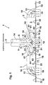
- the injector air outlet 1 shows an overview of injector air outlet 1 for temperature and flue gas monitoring of closed fuselage areas 11 of an aircraft.
- the injector air outlet 1 consists of a housing, the body wall 2 of which includes an injector mixing chamber 3.
- the shape of the housing of the injector air outlet 1 is significantly influenced by the horizontal course of the injector mixing chamber 3 (shown in longitudinal section).
- a supply air inlet 4 (a supply air opening), which is excluded from the body wall 2.
- An air branching element 6 projecting vertically into the injector mixing chamber 3 is connected to the supply air inlet 4, the connection area 62 of which (taking into account the flow cross section of the supply air) is positively connected to the edge region of the inner wall of the body located next to the air inlet 4.
- the connection area 62 of the air branch element 6 has two T-shaped air branches 61 projecting into the injector mixing chamber 3, which run horizontally within the injector mixing chamber 3.
- the supply air inlet 4 is expanded with a vertically directed supply air connector 14 (an extension pipe piece) which (taking into account the flow cross section of the supply air) is positively attached (on the body wall 2) to the edge region of the outer wall of the body located next to the air inlet 4.
- the air branches 61 are designed as pipe elbows, the end-side pipe transition of which merges on one side into a wall region with a united elbow cross section, which represents the (so-called) connection region 62 of the air branch element 6 (with a tubular cross section).
- the non-curved, horizontally running pipe end region of the two pipe elbows opens into the injector mixing chamber 3.
- a filler element 15 is attached to the bend of the two (as) pipe elbows (designed air branches 61) which faces the wall of the pipe elbows and the horizontal course of the pipe end regions of the pipe elbows is adjusted.
- auxiliary air inlet 9 an inlet opening for an exhaust air 10 of the closed fuselage area
- This secondary air inlet 9 is arranged opposite the filling element 15. It divides the secondary air duct 8 in two horizontally located secondary air duct ducts 81, which extend sideways (left and right sides next to) the secondary air inlet 9.
- the partial wall section 21 of the body wall 2 closes with the outlet at the secondary air duct 82 ending air flow cross section of the secondary air duct 8. It is for completeness mentions that the sub-wall section 21 is followed by further subsequent wall sections 22 are that border on them in a horizontal position.
- the sensor unit 12 consists of a temperature sensor and a sensor sensitized to flue gas particles. Both sensors are separate with a control and / or warning unit (external to the injector air outlet) is (are) positioned within the fuselage and their function is discussed in more detail later is electrically connected.
- the temperature sensor with a Air temperature control unit and the sensor sensitized to flue gas particles with a smoke alarm unit connected via appropriate signal lines.
- the air flow cross section of the two pipe elbows (the two air branches 61) of the air branch element 6 there is at least one air flow-promoting grille 16 which spans the curvature area of the two pipe elbows.
- the air flow cross section of the two air outlet end regions 17 of the injector mixing chamber 3, which extends vertically of the exhaust air outlet 13 (up to the region of the inner wall of the body above it), comprises at least one further air guide grille 16 which promotes air flow.
- the injector outlet 3 represents a self-sufficient unit projecting into the fuselage region 11, which in the Interior lining of the fuselage is integrated.
- the air branches 61 of the air branch element 6 and the secondary air duct 8 and the area of the body wall 2 of the Injector outlet 3, the partial wall area 21 and the adjacent wall areas adjacent to it 22 includes, are parallel to the interior trim and are arranged side by side, wherein the supply air inlet 4 is located in the interior lining, which (as explained later) by there is connected to the fuselage internal air distribution network attached to the fuselage.
- the injector air outlet 1 within closed fuselage areas of the aircraft is discussed in more detail below.
- the injector air outlet 1 is used for temperature and flue gas monitoring of the cargo hold areas in order to prevent the impending dangers prophylactically.
- the air conditioning and ventilation of such fuselage areas is operated.
- the (as described above) installed injector air outlet 1 is connected to the air intake network (not shown) in the fuselage connector 14. From there, part of the temperature-controlled (mixed air as conditioned) recirculation air is fed as supply air 5.
- the supply air flow of the supply air 5 flows (under air pressure) via the supply air inlet 4 of the injector air outlet 1 into the air branch element 6.
- the supply air flow which is a characteristic driver air flow, is determined by the two Air branches 61 (elbows), which are integrated in the air branch element 6, in two oppositely directed supply air partial flows 51 divided (according to the above description the injector air outlet 1) outlet of the air branch branches 61 (elbow) horizontally and parallel to the body wall 2 of the injector air outlet 1 into the horizontal one Flow in injector mixing chamber 3.
- the injector 7 driver flow gland
- the Supply air flow 5 the necessary pulse so that it has a negative pressure in the injector mixing chamber 3 generated.
- the injector air outlet 1 sucks via the (so-called) Secondary air inlet 9 from the fuselage area 11 (shown in FIG. 1) (the cargo hold) Exhaust air 10, the temperature content and flue gas particle concentration of which must be monitored.
- the exhaust air flow flows in on both sides of the secondary air duct ducts 81 of the secondary air duct 8, near the relevant secondary air outlet 82 of the individual secondary air duct passage 81 (aforementioned) sensor unit 12 happens.
- the temperature and the smoke particle fraction of the exhaust air 10 are sensed and then converted into corresponding signals that correspond to the determined states.
- the monitoring result is then sent via signal lines (not shown), which are connected to the sensors, to the temperature and / or smoke alarm unit (an internal fuselage monitoring system), which carries out a central evaluation of the monitoring result and, if necessary, electronically triggers changes in the controlled fuselage area.
- the exhaust air 10 (secondary air) of the fuselage area 11 (of the cargo hold) flowing out at the secondary air outlet 82 of the two secondary air duct ducts 81 will unite in the injector mixing chamber 3 with the supply air 5 of the fuselage-internal air distribution network.
- the combined air streams will then flow as recirculating injector mixed air 19 in the horizontal direction through the air flow cross section of the injector mixing chamber 3, which then flows to the (so-called) air outlet end area 17 located at the outlet of the injector mixing chamber 3 and via the relevant exhaust air inlet 13 (excluded from the body wall 22 of the injector air outlet 1)
- Fuselage area 11 (the cargo hold) flows in.
- the air guide grilles 16 arranged within the air outlet end region 17 favor the flow behavior of the injector mixed air 19.
- the injector mixed air recirculated at the exhaust air outlet 13 of the injector air outlet 1 19 a room air flow profile with a strong air velocity field (with high air velocity) and strong air mixing of the air areas blown by it with decoupling from Load and / or load state is generated in the fuselage area 11, whereby (there) a prevents local air temperature stratification and local homogeneous temperature and smoke distribution is achieved.
- the procedural characterizing the monitoring process Sequences are repeated continuously and permanently.
- the air outlet designed according to the injector principle a source-sink distribution for the freight flow profile of a passenger or transport aircraft which creates a strong speed field in the cargo hold as well as a large amount of air is supplied to the secondary air inlet 9 (bypass duct inlet). from that this results in a strong mixing of the cargo hold air with a decoupling from the load condition.
- the good mixing leads to a homogeneous temperature and (in the unfavorable Case) smoke distribution.
- the recirculation of the exhaust air from the cargo hold to the bypass duct 8 ensures that the two sensors of the sensor unit 12 (for their intended use) Find optimal conditions.
- the sensors produce a load-independent minimized measurement error of the monitoring result, which also the reliability of the Temperature control and smoke warning significantly increased.
- the temperature control function and the response behavior of the smoke alarm devices installed in the aircraft - compared to the traditional solutions in aircraft construction - significantly improved and for the Aircraft operators (airliners) safer.
- the large amount of recirculation of the exhaust air outlet 13 The injector mixed air 19 leaving the injector air outlet 1 generates a room air flow profile at great speed, which is why such a good air mixing of the existing, representative cargo hold air is reached and thus also temperature stratification this cargo hold air is prevented.
Landscapes
- Health & Medical Sciences (AREA)
- General Health & Medical Sciences (AREA)
- Pulmonology (AREA)
- Engineering & Computer Science (AREA)
- Aviation & Aerospace Engineering (AREA)
- Ventilation (AREA)
- Jet Pumps And Other Pumps (AREA)
- Fire-Detection Mechanisms (AREA)
- Exhaust Gas After Treatment (AREA)
Claims (17)
- Buse d'aération pour zones de fuselage fermées d'un avion dont la paroi de bâti (2) enserre une chambre de mélange à injecteur, avec une arrivée d'air amené (4) dégagée de la paroi de bâti (4) et par l'intermédiaire de laquelle un air de recirculation à réglage de température émanant d'un réseau de distribution d'air à l'intérieur du fuselage peut être acheminé comme air amené (5), sur laquelle repose un élément répartiteur d'air (6) faisant saillie dans la chambre de mélange à injection (3) et répartissant le courant d'air amené, une dérivation d'air (61) ayant été dérivée de l'élément de dérivation d'air, dérivation à travers laquelle un courant d'air amené (4) passant par l'arrivée d'air amené (4) s'engouffre dans la chambre de mélange (3), ledit courant d'air amené recevant, après le passage d'une douille d'injection (7) installée près de la sortie de la dérivation d'air (61), une impulsion nécessaire de manière à produire dans la chambre de mélange à injecteur (3) une sous-pression d'air, une arrivée d'air secondaire (9) débouchant dans un canal d'air secondaire (8) localisé dans la chambre de mélange à injecteur (3) ayant été dégagé de la paroi de bâti (2), sous-pression à travers laquelle un air d'échappement (10) d'une zone de fuselage (11) peut être aspiré comme air secondaire dans le canal d'air secondaire (8), l'air d'échappement (10) aspiré étant, après le passage de l'entrée d'air secondaire (9), dévidé dans le canal d'air secondaire (8) vers la chambre de mélange à injecteur (3), au moins une sortie d'air d'échappement (13) ayant été dégagée de la paroi de bâti (2), sortie d'air d'échappement au travers de laquelle les courants d'air amené (5) du réseau de distribution de l'air et de l'air d'échappement (10) de la zone de fuselage (11) réunis dans la chambre de mélange à injecteur (3) pouvant être ramenés comme air de mélange à injecteur (19) recirculé dans la zone de fuselage (11),
caractérisé en ce que l'élément de dérivation de l'air (6) présente deux dérivations d'air (61) dérivées par rapport à une zone de raccordement (62) de l'élément de dérivation d'air (6) apposée avec adhérence sur l'entrée d'air amené (4) ou dérivées en forme de T par rapport à une rallonge suivant la zone de raccordement (62) et qui répartissent le courant d'air amené de telle sorte que les courants partiels d'air amené (51) représentent un courant d'air propulseur caractéristique qui, après le passage de la douille d'injection (7) logée près de la sortie de la dérivation d'air concernée (61), reçoit l'impulsion nécessaire de telle sorte que le courant partiel d'air amené produise, dans la chambre de mélange à injecteur (3), une sous-pression d'air, les dérivations d'air (61) et une section de paroi partielle (21) de la paroi de bâti (2) de la buse d'aération (3) délimitant le canal d'air secondaire (8) horizontal, et l'entrée d'air secondaire (9) ayant été dérivée de la partie centrale de la section de paroi partielle (21), entrée d'air secondaire au travers de laquelle l'air d'échappement (10) de la zone de fuselage (11) étant, à cause de la sous-pression d'air existante, aspirée comme air secondaire dans le canal d'air secondaire (8), de telle sorte que l'air d'échappement (10) aspiré est dérivé, après le passage de l'entrée d'air secondaire (9), dans les couloirs des canaux d'air secondaires (81) du canal d'air secondaire (8), en direction de la chambre de mélange à injecteur (3), et au moins une sortie d'air d'échappement (13) de la chambre de mélange à injecteur (3) ayant dérivé, à chaque fois, des segments de la paroi suivante (22) de la paroi de bâti (2) disposés en amont, segments qui sont attenants à la section de paroi partielle (21), les courants d'air amené (5) du réseau de interne de distribution d'air et les courants d'air d'échappement (10) de la zone fuselage (11à réunis dans la chambre de mélange à injecteur (3) étant ramenés dans la zone de fuselage (11) à travers la sortie d'air d'échappement. - Buse d'aération selon la revendication 1, caractérisée en ce que une unité à capteur (12) captant de manière sensorielle la température et le pourcentage de particules de fumée de l'air d'échappement (10) de la zone de fuselage (11) a été installée à l'intérieur de la section transversale d'écoulement du canal d'air secondaire (8) et convertissant les situations communiquées dans des signaux correspondants acheminés vers une unité de réglage de la température raccordée à l'unité à capteur, à l'extérieur, et vers une unité émettant des signaux d'avertissement en cas de fumée raccordée à l'extérieur, l'unité à capteur (12) ayant été installée près d'au moins une des sorties d'air secondaire (82) concernée du canal d'air secondaire (8) et à l'intérieur de la section transversale d'écoulement du canal d'air secondaire (8).
- Bouche d'aération selon la revendication 1, caractérisée en ce que un raccord d'air amené (14) relié à un réseau de distribution d'air situé à l'intérieur du fuselage a été disposé en dehors de la paroi de bâti (2), contre la sortie d'air amené (4) .
- Bouche d'aération selon la revendication 1, caractérisée en ce que au moins deux tubes coudés dont la zone d'extrémité de tuyau non courbe et horizontale débouche dans la chambre de mélange à injecteur (3), un élément de remplissage (15) adapté, en face de l'entrée d'air secondaire (9), au trajet horizontal des segments d'extrémité, ayant été fixé aux arcs orientés l'un vers l'autre des deux tubes coudés.
- Bouche d'aération selon la revendication 1, caractérisée en ce que au moins une grille de conduite d'air (16) favorisant l'écoulement d'air a été disposé au centre de la section transversale d'écoulement de la dérivation d'air individuelle (61).
- Bouche d'aération selon la revendication 5, caractérisée en ce que la première grille de conduite d'air (16) a été disposée de manière à enjamber le segment de dérivation en forme de T.
- Bouche d'aération selon les revendications 4 et 5, caractérisée en ce que au moins une première grille de conduite d'air (16) favorisant l'écoulement d'air et enjambant le segment de courbure des deux tubes coudés a été disposée au centre de la section transversale d'écoulement d'air.
- Bouche d'aération selon la revendication 1, caractérisée en ce que la section transversale d'écoulement d'air de la sortie d'air d'échappement (13) de la chambre de mélange à injecteur (3) enserre un segment d'extrémité de sortie d'air (17) de la chambre de mélange à injecteur (3), segment à l'intérieur duquel au moins une deuxième grille de conduite d'air (16) favorisant un écoulement d'air a été disposée.
- Bouche d'aération selon la revendication 2, caractérisée en ce que au moins un capteur de température et un capteur sensibilisé aux particules de gaz de fumée raccordé de manière fonctionnelle et par voie électrique à l'unité de réglage de la température de l'air et à l'unité donnant des signaux d'avertissement en cas de fumée ont été intégrés à l'unité à capteur (12).
- Bouche d'aération selon la revendication 1, caractérisé en ce que la zone de la paroi de bâti (2) de la bouche d'aération (3) de laquelle ont été dégagées l'entrée d'air secondaire (9) et la sortie d'air d'échappement (13) a été intégrée dans un revêtement de l'espace intérieur revêtant la zone de fuselage (11), les ouvertures de l'entrée d'air secondaire (9) et de la sortie d'air d'échappement (13) correspondante de la chambre de mélange à injecteur (3) ayant été évidées du revêtement de l'espace intérieur.
- Bouche d'aération selon la revendication 1, caractérisée en ce que la zone de la paroi de bâti (2) de la sortie à injecteur (3) comprenant la zone de paroi partielle (21) et les zones de la paroi suivante (22) attenant à la zone de paroi partielle a été intégrée dans un revêtement d'espace intérieur revêtant la zone de fuselage (11), les ouvertures de l'entrée d'air secondaire (9) et de la sortie d'air d'échappement (13) correspondante de la chambre de mélange à injecteur (3) ayant été évidées du revêtement de l'espace intérieur.
- Bouche d'aération selon la revendication 1, caractérisée en ce que la bouche d'aération (3) est une unité autarcique faisant saillie dans la zone de fuselage (11) et intégrée dans le revêtement de l'espace intérieur du fuselage de l'avion, et en ce que les dérivations d'air (61) de l'élément de dérivation d'air (6) et du canal d'air secondaire (8) ainsi que le segment de la paroi de bâti (2) de la bouche d'aération (3), duquel a été évidé la sortie d'air secondaire (9) et la sortie d'air d'échappement (13), sont parallèles au revêtement de l'espace intérieur et disposés les uns à côté des autres, l'entrée d'air amené (4) ayant été localisée dans le revêtement de l'espace intérieur, auquel le réseau de distribution d'air situé à l'intérieur du fuselage et fixé au fuselage d'avion a été raccordé.
- Bouche d'aération selon la revendication 12, caractérisée en ce que la paroi de bâti (2) de la bouche d'aération (3) se rapporte à la zone comprenant la zone de paroi partielle (21) et les segments de la paroi suivante attenant à la zone de paroi partielle.
- Bouche d'aération selon la revendication 10, caractérisée en ce que le segment de la paroi de bâti (2) de la bouche d'aération (3), duquel l'entrée d'air secondaire (9) et la sortie d'air d'échappement (13) ont été dégagées, a été remplacé par une paroi interne (18) revêtant le fuselage d'avion.
- Bouche d'aération selon la revendication 11, caractérisée en ce que le segment de la paroi de bâti (2) de la bouche d'aération (3) comprenant la zone de paroi partielle (21) et les segments de la paroi suivante (22) attenant à la zone de paroi partielle a été remplacé par la paroi interne (18) revêtant le fuselage de l'avion.
- Procédé de soufflage de zones de fuselage (11) fermées d'un avion, en particulier à l'intérieur des zones de l'espace de fret, avec une bouche d'aération (1) selon la revendication 1 activée en même temps pour climatiser et aérer les zones de fuselage (11) d'un avion, et avec les étapes de procédé suivantes, selon lesquellesles courants d'air amené (5) et d'air secondaire allant par ailleurs passer comme air de mélange à injecteur recirculé (19) dans une grille de conduite d'air (16) favorisant l'écoulement d'air et située à la sortie d'air d'échappement (13), à l'intérieur d'un segment d'extrémité de sortie (17) de la chambre de mélange à injecteur (3) et avec l'air de mélange à injecteur recirculé à la sortie d'air d'échappement (13) de la sortie d'air à injecteur (1), un profil d'écoulement d'air ambiant avec un champ de vitesse d'air puissant et un mélange d'air puissant des zones d'air soufflées par le mélange est produit avec désaccouplement de la situation de chargement et / ou de sollicitation dans la zone de fuselage (11), une stratification locale de la température de l'air étant ainsi évitée à cet endroit et une répartition locale homogène de la température et de la fumée étant obtenue.une partie de l'air de recirculation à réglage de température, préparé et soutiré d'un réseau de distribution d'air situé à l'intérieur du fuselage de l'avion a été acheminé comme air amené (5) vers la bouche d'aération (1),le courant d'air amené d'un élément de dérivation d'air (6) raccordé à l'entrée d'air amené (4) de la bouche d'aération et s'enfonçant dans une chambre de mélange à injecteur (3) est introduit directement ou séparément en fonction de l'écoulement, le courant d'air amené introduit directement allant s'écouler dans la chambre de mélange à injecteur (3), horizontalement et parallèlement à la paroi de bâti (2) de l'entrée à injecteur ou au moins deux courants partiels d'air amené (51) orientés dans des directions opposées allant s'écouler dans la chambre de mélange à injecteur (3), horizontalement et parallèlement à la paroi de bâti (2) de l'entrée à injecteur,le courant partiel d'air amené (51) individuel qui représente un courant d'air propulseur caractéristique passera une douille d'injection (7) reposant près de la sortie de l'élément de dérivation d'air (6) et recevra, via la douille d'injection (7), une impulsion nécessaire qui produira une sous-pression d'air dans la chambre de mélange à injecteur (3),l'air d'échappement (10) est aspiré à partir de la zone de fuselage dans un canal d'air secondaire (8) intégré dans la bouche d'aération, le flux de courant d'air d'échappement allant tout d'abord, suite à la sous-pression d'air produite, s'introduire dans la chambre de mélange à injecteur (3) qui s'écoulera à travers une entrée d'air secondaire (9) d'un canal d'air secondaire (8) qui divise le canal d'air secondaire (8) en couloirs de canaux d'air secondaire,les courants d'air de l'air amené (5) et de l'air d'échappement (10) de la zone de fuselage (11) se réuniront dans la chambre de mélange à injecteur (3) puis seront ramenées, comme air de mélange à injecteur recirculé (19), dans la zone de fuselage (11), par l'intermédiaire d'au moins une sortie d'air d'échappement (13) évidée de la paroi de bâti (2) de la bouche d'aération,
- Procédé selon la revendication 16, caractérisé en ce que l'air secondaire aspiré devient, près d'une sortie d'air secondaire (82) du couloir de canal d'air secondaire à travers lequel l'air d'échappement (10) aspiré s'écoule parallèlement et à côté des courants partiels d'air amené (51) jusque dans la chambre de mélange à injecteur (3), une unité à capteur (12) intégrée à cet endroit dans la section transversale de l'écoulement, avec laquelle la température et les particules de fumée de l'air d'échappement (10) sont saisies par capteurs puis converties en signaux correspondant aux situations saisies, lesdits signaux étant conduits jusqu'à une unité de réglage de la température et une unité émettant des signaux d'avertissement en cas de fumée, raccordées à l'unité à capteur.
Applications Claiming Priority (2)
| Application Number | Priority Date | Filing Date | Title |
|---|---|---|---|
| DE19728595A DE19728595C1 (de) | 1997-07-04 | 1997-07-04 | Injektorluftauslaß zur Temperatur- und Rauchgasüberwachung |
| DE19728595 | 1997-07-04 |
Publications (3)
| Publication Number | Publication Date |
|---|---|
| EP0888965A2 EP0888965A2 (fr) | 1999-01-07 |
| EP0888965A3 EP0888965A3 (fr) | 2000-04-12 |
| EP0888965B1 true EP0888965B1 (fr) | 2003-12-17 |
Family
ID=7834640
Family Applications (1)
| Application Number | Title | Priority Date | Filing Date |
|---|---|---|---|
| EP98103977A Expired - Lifetime EP0888965B1 (fr) | 1997-07-04 | 1998-03-06 | Buse d'aération pour la surveillance de la température et des fumées |
Country Status (4)
| Country | Link |
|---|---|
| US (1) | US6024639A (fr) |
| EP (1) | EP0888965B1 (fr) |
| DE (2) | DE19728595C1 (fr) |
| ES (1) | ES2212156T3 (fr) |
Families Citing this family (36)
| Publication number | Priority date | Publication date | Assignee | Title |
|---|---|---|---|---|
| DE19927606C2 (de) * | 1999-06-17 | 2002-02-28 | Eads Airbus Gmbh | Anordnung zur Klimatisierung von Unterflurbereichen eines Passagierflugzeuges |
| FR2802894A1 (fr) * | 1999-12-28 | 2001-06-29 | Dassault Aviat | Dispositif de recirculation et de rafraichissement de l'air d'une cabine d'aeronef |
| DE10361392B4 (de) * | 2003-12-29 | 2009-07-30 | Airbus Deutschland Gmbh | Luftverteilungssystem |
| DE10361654B4 (de) * | 2003-12-30 | 2008-09-04 | Airbus Deutschland Gmbh | Verfahren und Vorrichtung zum Klimatisieren von Flugzeugkabinen |
| US8336821B2 (en) * | 2005-03-31 | 2012-12-25 | The Boeing Company | Systems and methods for cargo compartment air conditioning using recirculated air |
| DE102006005543B4 (de) | 2006-02-07 | 2010-06-24 | Airbus Deutschland Gmbh | Flugzeugklimatisierungssystem mit Zyklonausströmern |
| DE102006017012B4 (de) * | 2006-04-11 | 2011-01-13 | Airbus Operations Gmbh | Kühlsystem und Frachtcontainer |
| DE102006017004B3 (de) * | 2006-04-11 | 2007-10-25 | Airbus Deutschland Gmbh | Vorrichtung zur Vermischung von Frischluft und Heizluft sowie Verwendung derselben in einem Belüftungssystem eines Flugzeuges |
| DE102006018404B4 (de) * | 2006-04-20 | 2020-11-26 | Airbus Operations Gmbh | Lärmoptimierter Luftverteiler |
| SE531961C2 (sv) * | 2007-10-16 | 2009-09-15 | Mccii Holdings Ab | Förfarande och anordning för lufthantering |
| DE602007008583D1 (de) * | 2007-11-26 | 2010-09-30 | Honeywell Aerospace Bv | Flugzeugklimaanlage |
| WO2010111284A1 (fr) * | 2009-03-23 | 2010-09-30 | Heico Corporation | Filtre de capteur de température pour cabine d'aéronef |
| DE102009038277A1 (de) | 2009-08-20 | 2011-03-03 | Airbus Operations Gmbh | Selbstkontrolle von Halbleitergassensoren zur Erkennung von Vergiftungserscheinungen durch organische Silikonverbindungen |
| US8882400B2 (en) * | 2010-10-29 | 2014-11-11 | General Electric Company | Solids feeder discharge port |
| EP2666721B1 (fr) | 2012-05-24 | 2019-05-15 | Airbus Operations GmbH | Système de détection de fumée et méthode pour le fonctionnement d'un système de détection de fumée |
| US9440743B2 (en) | 2012-08-09 | 2016-09-13 | Hamilton Sundstrand Corporation | Cabin air compressor outlet duct |
| US9381787B2 (en) * | 2012-10-26 | 2016-07-05 | Hamilton Sundstrand Corporation | Generally wye shaped elbow for cabin air flow system |
| US9075007B2 (en) * | 2012-12-12 | 2015-07-07 | American Mine Research, Inc. | Active sampling smoke sensor for the mining industry |
| US20140352913A1 (en) * | 2013-05-31 | 2014-12-04 | Hamilton Sundstrand Corporation | Aircraft refrigeration unit evaporator heater |
| US20150314666A1 (en) * | 2014-05-02 | 2015-11-05 | Hamilton Sundstrand Corporation | Aircraft environmental conditioning system and method |
| EP3090948A1 (fr) * | 2015-05-08 | 2016-11-09 | Raymond R M Wang | Procédé et appareil de modification de flux d'air |
| WO2017062789A1 (fr) * | 2015-10-08 | 2017-04-13 | Bombardier Inc. | Appareil et système de détection de température d'air de cabine d'aéronef utilisant un flux d'air passif |
| CN106196285B (zh) * | 2016-07-29 | 2019-03-01 | 青岛海尔空调器有限总公司 | 一种立式空调及其送风控制方法 |
| CN106123264B (zh) * | 2016-07-29 | 2019-03-01 | 青岛海尔空调器有限总公司 | 一种立式空调及其送风控制方法 |
| DE102017119751A1 (de) * | 2017-08-29 | 2019-02-28 | Airbus Operations Gmbh | Kabinendeckenverkleidungspaneel für eine Flugzeugkabine |
| CN207907312U (zh) * | 2018-01-31 | 2018-09-25 | 宁波方太厨具有限公司 | 一种吸油烟机的出风结构 |
| CN109703756B (zh) * | 2019-02-19 | 2023-08-15 | 南京工业职业技术学院 | 一种烟囱检测用无人机 |
| CN110339523B (zh) * | 2019-05-29 | 2021-06-04 | 江西中科冠物联网科技有限公司 | 一种智能监控消防器 |
| US11560043B2 (en) * | 2019-07-31 | 2023-01-24 | The Boeing Company | Passenger cabin air distribution system and method of using |
| US11884403B2 (en) | 2020-09-09 | 2024-01-30 | The Boeing Company | Air distribution nozzles, aircraft that include air distribution nozzles, and methods of utilizing air distribution nozzles |
| US11958616B2 (en) * | 2020-09-09 | 2024-04-16 | The Boeing Company | Air distribution nozzles, aircraft that include air distribution nozzles, and methods of utilizing air distribution nozzles |
| EP4008636B1 (fr) | 2020-12-03 | 2024-05-01 | The Boeing Company | Systèmes de contrôle environnemental d'un aéronef comprenant des entrelaceurs d'écoulement d'air et procédés de contrôle d'écoulement d'air à l'intérieur d'un aéronef |
| EP4082909B1 (fr) * | 2021-04-28 | 2024-07-03 | The Boeing Company | Buses de distribution d'air, aéronef comprenant des buses de distribution d'air et procédés d'utilisation des buses de distribution d'air |
| JP2022170721A (ja) * | 2021-04-28 | 2022-11-10 | ザ・ボーイング・カンパニー | 空気分散ノズル、空気分散ノズルを備える航空機、及び空気分散ノズルを利用する方法 |
| CN113757227B (zh) * | 2021-09-17 | 2025-01-21 | 彭萍芳 | 定向回流装置 |
| US12358629B2 (en) * | 2022-06-17 | 2025-07-15 | The Boeing Company | Air distribution panel for distributing air and sensing environmental conditions |
Family Cites Families (9)
| Publication number | Priority date | Publication date | Assignee | Title |
|---|---|---|---|---|
| BE509287A (fr) * | 1948-05-01 | |||
| US3368406A (en) * | 1966-02-02 | 1968-02-13 | Mc Donnell Douglas Corp | Temperature sensor air augmenter |
| US3687054A (en) * | 1970-11-24 | 1972-08-29 | Lockheed Aircraft Corp | Air outlet apparatus |
| CH546989A (de) * | 1972-12-06 | 1974-03-15 | Cerberus Ag | Verfahren und vorrichtung zur brandmeldung. |
| US4181253A (en) * | 1977-12-23 | 1980-01-01 | Connor Engineering & Manufacturing, Inc. | Ceiling air diffuser and induction apparatus |
| GB8527201D0 (en) * | 1985-11-05 | 1985-12-11 | British Aerospace | Fluid flow distribution ducts |
| US5420440A (en) * | 1994-02-28 | 1995-05-30 | Rel-Tek Corporation | Optical obscruation smoke monitor having a shunt flow path located between two access ports |
| DE19509773C1 (de) * | 1995-03-17 | 1996-06-27 | Daimler Benz Aerospace Airbus | Belüftungssystem zur Verminderung der Konzentration von Verunreinigungen im Flugzeugpassagierbereich |
| US5926098A (en) * | 1996-10-24 | 1999-07-20 | Pittway Corporation | Aspirated detector |
-
1997
- 1997-07-04 DE DE19728595A patent/DE19728595C1/de not_active Expired - Lifetime
-
1998
- 1998-03-06 ES ES98103977T patent/ES2212156T3/es not_active Expired - Lifetime
- 1998-03-06 EP EP98103977A patent/EP0888965B1/fr not_active Expired - Lifetime
- 1998-03-06 DE DE59810438T patent/DE59810438D1/de not_active Expired - Lifetime
- 1998-07-01 US US09/108,859 patent/US6024639A/en not_active Expired - Lifetime
Also Published As
| Publication number | Publication date |
|---|---|
| EP0888965A3 (fr) | 2000-04-12 |
| EP0888965A2 (fr) | 1999-01-07 |
| DE59810438D1 (de) | 2004-01-29 |
| DE19728595C1 (de) | 1998-09-17 |
| ES2212156T3 (es) | 2004-07-16 |
| US6024639A (en) | 2000-02-15 |
Similar Documents
| Publication | Publication Date | Title |
|---|---|---|
| EP0888965B1 (fr) | Buse d'aération pour la surveillance de la température et des fumées | |
| DE19927606C2 (de) | Anordnung zur Klimatisierung von Unterflurbereichen eines Passagierflugzeuges | |
| DE69021836T2 (de) | Verdünnungssystem mit Mehrrohrströmungsteiler. | |
| DE19680305C2 (de) | Abgasrezirkulationssystem (EGR) für einen Innenverbrennungsmotor | |
| DE10000669C2 (de) | Luftmassenstromregelsystem mit Druckhöhenkorrektur für ein Verkehrsflugzeug | |
| EP1258603B1 (fr) | Moteur pour véhicule comprenant un dispositif de frein moteur et un système de recirculation des gaz d'échappement | |
| EP2563660A2 (fr) | Structure de support à utiliser dans un système d'amenée d'air, système d'alimentation pourvu d'une telle structure de support, et procédé de configuration associé | |
| DE102009015188B4 (de) | Anlage zur Entnahme von Abgasproben von Verbrennungskraftmaschinen und deren Verwendung | |
| DE102013008620A1 (de) | Flugzeugkühlsystem und Verfahren zum Betreiben eines Flugzeugkühlsystems | |
| DE102008058451A1 (de) | Verfahren und System zur Notbelüftung einer Flugzeugkabine im Fall eines Lecks im Bereich eines Luftmischers | |
| DE4445380A1 (de) | Anordnung von Bauteilen zur Belüftung, Heizung und/oder Klimatisierung eines Kraftfahrzeugs | |
| EP1078853B1 (fr) | Système de climatisation pour la soute à fret d'un aèronef de passagers | |
| DE102016200648A1 (de) | Innenverkleidungselement und Transportmittel | |
| DE3605603C2 (fr) | ||
| DE20105821U1 (de) | Schienenfahrzeug mit klimatisiertem Führerhaus | |
| DE9420222U1 (de) | Anordnung von Bauteilen zur Belüftung, Heizung und/oder Klimatisierung eines Kraftfahrzeugs | |
| EP3702233B1 (fr) | Véhicule ferroviaire à plusieurs pièces doté d'un raccord de voiture composé d'une voiture support et de deux modules de passage entre les voitures | |
| EP0521269A1 (fr) | Dispositif de climatisation ou chauffage dans le côté avant d'un omnibus | |
| EP1394010B1 (fr) | Procédé de vérification de l'étanchéité des véhicules | |
| EP4466172B1 (fr) | Véhicule pour le transport de passagers avec un dispositif de protection contre la pression | |
| DE112019005395T5 (de) | PM-Sensor | |
| DE102017215470A1 (de) | Klimaanlage | |
| DE102017223338B3 (de) | Fahrzeug mit Temperaturregelung für den Fahrgastinnenraum | |
| DE19940165B4 (de) | Anordnung zur Klimatisierung von Unterflurbereichen eines Pasagierflugzeuges | |
| DE19756731A1 (de) | Achsträgerkonstruktion eines Kraftwagens |
Legal Events
| Date | Code | Title | Description |
|---|---|---|---|
| PUAI | Public reference made under article 153(3) epc to a published international application that has entered the european phase |
Free format text: ORIGINAL CODE: 0009012 |
|
| AK | Designated contracting states |
Kind code of ref document: A2 Designated state(s): DE ES FR GB NL SE |
|
| AX | Request for extension of the european patent |
Free format text: AL;LT;LV;MK;RO;SI |
|
| RAP3 | Party data changed (applicant data changed or rights of an application transferred) |
Owner name: DAIMLERCHRYSLER AEROSPACE AIRBUS GESELLSCHAFT MIT |
|
| PUAL | Search report despatched |
Free format text: ORIGINAL CODE: 0009013 |
|
| AK | Designated contracting states |
Kind code of ref document: A3 Designated state(s): AT BE CH DE DK ES FI FR GB GR IE IT LI LU MC NL PT SE |
|
| AX | Request for extension of the european patent |
Free format text: AL;LT;LV;MK;RO;SI |
|
| RIC1 | Information provided on ipc code assigned before grant |
Free format text: 7B 64D 13/06 A, 7B 64C 13/00 B |
|
| 17P | Request for examination filed |
Effective date: 20000304 |
|
| RAP1 | Party data changed (applicant data changed or rights of an application transferred) |
Owner name: EADS AIRBUS GMBH |
|
| AKX | Designation fees paid |
Free format text: DE ES FR GB NL SE |
|
| RAP1 | Party data changed (applicant data changed or rights of an application transferred) |
Owner name: AIRBUS DEUTSCHLAND GMBH |
|
| 17Q | First examination report despatched |
Effective date: 20021204 |
|
| GRAH | Despatch of communication of intention to grant a patent |
Free format text: ORIGINAL CODE: EPIDOS IGRA |
|
| GRAA | (expected) grant |
Free format text: ORIGINAL CODE: 0009210 |
|
| GRAS | Grant fee paid |
Free format text: ORIGINAL CODE: EPIDOSNIGR3 |
|
| AK | Designated contracting states |
Kind code of ref document: B1 Designated state(s): DE ES FR GB NL SE |
|
| REG | Reference to a national code |
Ref country code: GB Ref legal event code: FG4D Free format text: NOT ENGLISH |
|
| REF | Corresponds to: |
Ref document number: 59810438 Country of ref document: DE Date of ref document: 20040129 Kind code of ref document: P |
|
| GBT | Gb: translation of ep patent filed (gb section 77(6)(a)/1977) |
Effective date: 20040305 |
|
| REG | Reference to a national code |
Ref country code: SE Ref legal event code: TRGR |
|
| REG | Reference to a national code |
Ref country code: ES Ref legal event code: FG2A Ref document number: 2212156 Country of ref document: ES Kind code of ref document: T3 |
|
| ET | Fr: translation filed | ||
| PLBE | No opposition filed within time limit |
Free format text: ORIGINAL CODE: 0009261 |
|
| STAA | Information on the status of an ep patent application or granted ep patent |
Free format text: STATUS: NO OPPOSITION FILED WITHIN TIME LIMIT |
|
| 26N | No opposition filed |
Effective date: 20040920 |
|
| REG | Reference to a national code |
Ref country code: ES Ref legal event code: PC2A Owner name: AIRBUS OPERATIONS GMBH Effective date: 20110930 |
|
| REG | Reference to a national code |
Ref country code: FR Ref legal event code: CD Owner name: AIRBUS OPERATIONS GMBH Effective date: 20111118 |
|
| REG | Reference to a national code |
Ref country code: FR Ref legal event code: PLFP Year of fee payment: 19 |
|
| PGFP | Annual fee paid to national office [announced via postgrant information from national office to epo] |
Ref country code: DE Payment date: 20160321 Year of fee payment: 19 Ref country code: NL Payment date: 20160321 Year of fee payment: 19 Ref country code: ES Payment date: 20160309 Year of fee payment: 19 |
|
| PGFP | Annual fee paid to national office [announced via postgrant information from national office to epo] |
Ref country code: SE Payment date: 20160321 Year of fee payment: 19 Ref country code: GB Payment date: 20160321 Year of fee payment: 19 Ref country code: FR Payment date: 20160321 Year of fee payment: 19 |
|
| REG | Reference to a national code |
Ref country code: DE Ref legal event code: R119 Ref document number: 59810438 Country of ref document: DE |
|
| REG | Reference to a national code |
Ref country code: SE Ref legal event code: EUG |
|
| REG | Reference to a national code |
Ref country code: NL Ref legal event code: MM Effective date: 20170401 |
|
| GBPC | Gb: european patent ceased through non-payment of renewal fee |
Effective date: 20170306 |
|
| PG25 | Lapsed in a contracting state [announced via postgrant information from national office to epo] |
Ref country code: SE Free format text: LAPSE BECAUSE OF NON-PAYMENT OF DUE FEES Effective date: 20170307 |
|
| REG | Reference to a national code |
Ref country code: FR Ref legal event code: ST Effective date: 20171130 |
|
| PG25 | Lapsed in a contracting state [announced via postgrant information from national office to epo] |
Ref country code: DE Free format text: LAPSE BECAUSE OF NON-PAYMENT OF DUE FEES Effective date: 20171003 Ref country code: NL Free format text: LAPSE BECAUSE OF NON-PAYMENT OF DUE FEES Effective date: 20170401 Ref country code: FR Free format text: LAPSE BECAUSE OF NON-PAYMENT OF DUE FEES Effective date: 20170331 |
|
| PG25 | Lapsed in a contracting state [announced via postgrant information from national office to epo] |
Ref country code: GB Free format text: LAPSE BECAUSE OF NON-PAYMENT OF DUE FEES Effective date: 20170306 |
|
| REG | Reference to a national code |
Ref country code: ES Ref legal event code: FD2A Effective date: 20180507 |
|
| PG25 | Lapsed in a contracting state [announced via postgrant information from national office to epo] |
Ref country code: ES Free format text: LAPSE BECAUSE OF NON-PAYMENT OF DUE FEES Effective date: 20170307 |