EP0889012A1 - Verfahren zum Füllen von Hohlräumen in Werkstücken oder Halbzeugen und Bauelement zum An- oder Einbau in ein Kraftfahrzeug - Google Patents
Verfahren zum Füllen von Hohlräumen in Werkstücken oder Halbzeugen und Bauelement zum An- oder Einbau in ein Kraftfahrzeug Download PDFInfo
- Publication number
- EP0889012A1 EP0889012A1 EP98111284A EP98111284A EP0889012A1 EP 0889012 A1 EP0889012 A1 EP 0889012A1 EP 98111284 A EP98111284 A EP 98111284A EP 98111284 A EP98111284 A EP 98111284A EP 0889012 A1 EP0889012 A1 EP 0889012A1
- Authority
- EP
- European Patent Office
- Prior art keywords
- carbon powder
- cavity
- foaming
- semi
- double
- Prior art date
- Legal status (The legal status is an assumption and is not a legal conclusion. Google has not performed a legal analysis and makes no representation as to the accuracy of the status listed.)
- Granted
Links
Images

Classifications
-
- B—PERFORMING OPERATIONS; TRANSPORTING
- B62—LAND VEHICLES FOR TRAVELLING OTHERWISE THAN ON RAILS
- B62D—MOTOR VEHICLES; TRAILERS
- B62D29/00—Superstructures, understructures, or sub-units thereof, characterised by the material thereof
- B62D29/001—Superstructures, understructures, or sub-units thereof, characterised by the material thereof characterised by combining metal and synthetic material
- B62D29/002—Superstructures, understructures, or sub-units thereof, characterised by the material thereof characterised by combining metal and synthetic material a foamable synthetic material or metal being added in situ
-
- B—PERFORMING OPERATIONS; TRANSPORTING
- B29—WORKING OF PLASTICS; WORKING OF SUBSTANCES IN A PLASTIC STATE IN GENERAL
- B29C—SHAPING OR JOINING OF PLASTICS; SHAPING OF MATERIAL IN A PLASTIC STATE, NOT OTHERWISE PROVIDED FOR; AFTER-TREATMENT OF THE SHAPED PRODUCTS, e.g. REPAIRING
- B29C44/00—Shaping by internal pressure generated in the material, e.g. swelling or foaming ; Producing porous or cellular expanded plastics articles
- B29C44/02—Shaping by internal pressure generated in the material, e.g. swelling or foaming ; Producing porous or cellular expanded plastics articles for articles of definite length, i.e. discrete articles
- B29C44/12—Incorporating or moulding on preformed parts, e.g. inserts or reinforcements
- B29C44/18—Filling preformed cavities
- B29C44/182—Filling flexible bags not having a particular shape
- B29C44/184—Filling flexible bags not having a particular shape and inserting the bags into preformed cavities
-
- C—CHEMISTRY; METALLURGY
- C04—CEMENTS; CONCRETE; ARTIFICIAL STONE; CERAMICS; REFRACTORIES
- C04B—LIME, MAGNESIA; SLAG; CEMENTS; COMPOSITIONS THEREOF, e.g. MORTARS, CONCRETE OR LIKE BUILDING MATERIALS; ARTIFICIAL STONE; CERAMICS; REFRACTORIES; TREATMENT OF NATURAL STONE
- C04B30/00—Compositions for artificial stone, not containing binders
-
- C—CHEMISTRY; METALLURGY
- C04—CEMENTS; CONCRETE; ARTIFICIAL STONE; CERAMICS; REFRACTORIES
- C04B—LIME, MAGNESIA; SLAG; CEMENTS; COMPOSITIONS THEREOF, e.g. MORTARS, CONCRETE OR LIKE BUILDING MATERIALS; ARTIFICIAL STONE; CERAMICS; REFRACTORIES; TREATMENT OF NATURAL STONE
- C04B38/00—Porous mortars, concrete, artificial stone or ceramic ware; Preparation thereof
- C04B38/009—Porous or hollow ceramic granular materials, e.g. microballoons
-
- F—MECHANICAL ENGINEERING; LIGHTING; HEATING; WEAPONS; BLASTING
- F01—MACHINES OR ENGINES IN GENERAL; ENGINE PLANTS IN GENERAL; STEAM ENGINES
- F01N—GAS-FLOW SILENCERS OR EXHAUST APPARATUS FOR MACHINES OR ENGINES IN GENERAL; GAS-FLOW SILENCERS OR EXHAUST APPARATUS FOR INTERNAL-COMBUSTION ENGINES
- F01N13/00—Exhaust or silencing apparatus characterised by constructional features
- F01N13/14—Exhaust or silencing apparatus characterised by constructional features having thermal insulation
-
- Y—GENERAL TAGGING OF NEW TECHNOLOGICAL DEVELOPMENTS; GENERAL TAGGING OF CROSS-SECTIONAL TECHNOLOGIES SPANNING OVER SEVERAL SECTIONS OF THE IPC; TECHNICAL SUBJECTS COVERED BY FORMER USPC CROSS-REFERENCE ART COLLECTIONS [XRACs] AND DIGESTS
- Y10—TECHNICAL SUBJECTS COVERED BY FORMER USPC
- Y10T—TECHNICAL SUBJECTS COVERED BY FORMER US CLASSIFICATION
- Y10T428/00—Stock material or miscellaneous articles
- Y10T428/249921—Web or sheet containing structurally defined element or component
- Y10T428/249953—Composite having voids in a component [e.g., porous, cellular, etc.]
- Y10T428/249955—Void-containing component partially impregnated with adjacent component
- Y10T428/249956—Void-containing component is inorganic
-
- Y—GENERAL TAGGING OF NEW TECHNOLOGICAL DEVELOPMENTS; GENERAL TAGGING OF CROSS-SECTIONAL TECHNOLOGIES SPANNING OVER SEVERAL SECTIONS OF THE IPC; TECHNICAL SUBJECTS COVERED BY FORMER USPC CROSS-REFERENCE ART COLLECTIONS [XRACs] AND DIGESTS
- Y10—TECHNICAL SUBJECTS COVERED BY FORMER USPC
- Y10T—TECHNICAL SUBJECTS COVERED BY FORMER US CLASSIFICATION
- Y10T428/00—Stock material or miscellaneous articles
- Y10T428/249921—Web or sheet containing structurally defined element or component
- Y10T428/249953—Composite having voids in a component [e.g., porous, cellular, etc.]
- Y10T428/249967—Inorganic matrix in void-containing component
-
- Y—GENERAL TAGGING OF NEW TECHNOLOGICAL DEVELOPMENTS; GENERAL TAGGING OF CROSS-SECTIONAL TECHNOLOGIES SPANNING OVER SEVERAL SECTIONS OF THE IPC; TECHNICAL SUBJECTS COVERED BY FORMER USPC CROSS-REFERENCE ART COLLECTIONS [XRACs] AND DIGESTS
- Y10—TECHNICAL SUBJECTS COVERED BY FORMER USPC
- Y10T—TECHNICAL SUBJECTS COVERED BY FORMER US CLASSIFICATION
- Y10T428/00—Stock material or miscellaneous articles
- Y10T428/249921—Web or sheet containing structurally defined element or component
- Y10T428/249953—Composite having voids in a component [e.g., porous, cellular, etc.]
- Y10T428/249986—Void-containing component contains also a solid fiber or solid particle
Definitions
- the present invention relates to a method for filling Cavities in workpieces or semi-finished products as well as a component, in particular workpiece or semi-finished product, for attachment or installation in a motor vehicle.
- DE-OS 38 26 012 describes a method for filling hollow bodies known, one in the cavity of the hollow body an open-cell foam existing body is completely covered with a gas-impermeable skin is.
- This skin has at least one opening at which a vacuum for compression when inserting the foam body of the foam body is created. After insertion the contracted foam body is let into the cavity expand by removing the vacuum so that it then the Fills the cavity.
- Another method for filling is known from DE 40 28 895 C1 of cavities known in which one compared to the cross section of the cavity to be filled has an excess foam body made of elastic and compressible plastic foam mechanically thanks to an undersize casing compressed from plastic and in the compressed state in the Body cavity is introduced. There is the compressed Foam body in its later position within the one to be filled Cavity temporarily mechanically secured.
- the plastic enveloping the foam body is only up to a certain limit temperature, so that by heating of the body cavity together with the foam body to at least the melting point of the coating The compression of the foam body is released, so that the foam body on the inside under tension creates the body cavity.
- DE 42 27 393 A1 discloses a carrier with an outer metal one Hollow body and a lightweight core is known, the Core carries an electrically conductive layer and below it Layer a coat with foamable by heat Has material and an already necessary for the foaming process Heat supply is used, for example for Welding the parts of a multi-part hollow body and / or for dip painting in hot paint.
- DE 40 38 979 A1 discloses a double tube with a rigid one Outer tube known, the inner tube of a plastic in situ deformed, radially expanded tubular body that forms a around the inner tube arranged against compression the inner surface of the outer tube presses.
- the invention is based on the object Process for filling cavities in workpieces or semi-finished products to improve in that the cavities to simpler Way are foamable. Furthermore, the Invention, the object of a component, in particular Workpiece or semi-finished product, for attachment or installation in a motor vehicle provide the cavities in a simpler way and Are foamable.
- the cavity to be foamed is used itself as a mold for the carbon foam, which in particular for double-walled workpieces, such as pipes and profiles, thus suitable for cavities with a sufficiently small cross-section is.
- the film bag is advantageously a folded pouch that is capable of folding when foaming the carbon powder with it unfold and expand so that an adjustment of the filling material to the contour to be foamed.
- plastic bags as they are from the prior art is known to be associated with carbon powder not suitable because of the high foaming temperatures of approx. 130 ° C the plastic would melt early and thus securing the position of the carbon powder is not guaranteed would.
- the heating takes place by one for further processing of the workpiece or semi-finished product necessary operation.
- Measure is taken anyway for a subsequent heating process energy to be used also for the foaming process. This is particularly evident in the design Claim 5 as advantageous, according to which for filling body cavities the carbon powder is already in the construction phase the body is inserted into the cavities with the body undergoes a dip painting and foaming takes place together with the baking of the dip lacquer.
- the heating takes place by commissioning the intended use of the Workpiece.
- This The procedure proves to be the case for workpieces that Operation to be heated up regularly, as special advantageous, such as in the design of the invention.
- the method of claim 7, wherein the filling of double-wall cavities of a double-walled exhaust pipe the carbon powder in the to be filled before final assembly Double-wall cavities are introduced and the foaming the first time the exhaust pipe reaches its operating temperature he follows.
- the component according to the invention at which is in particular a workpiece or semi-finished product, is intended for attachment or installation in a motor vehicle and has at least one closed cavity, in which thermally foamable carbon powder is secure is introduced, with the swelling of the carbon powder to form the cavity filling carbon foam heating the carbon powder together with the workpiece takes place and the particles of the carbon powder in Delivery state are smaller than after foaming.
- the heating for foaming takes place of the carbon powder by commissioning the Intended use of the component.
- the component is a double-walled, especially exhaust pipe with directly in the double-wall cavity filled carbon powder, and foaming occurs when the operating temperature is reached for the first time of the pipe.
- the component is a Profile beam (for example, a longitudinal beam or an A, B or C-pillar for a car body) with a secure position in the at least one cavity arranged, hermetically enclosed Aluminum foil bags containing carbon powder.
- a Profile beam for example, a longitudinal beam or an A, B or C-pillar for a car body
- the carbon powders containing aluminum foil bag before or in the body-in-white phase in the at least one cavity introduced to dip paint with the body run through so that the foaming together with the branding of the dip varnish.
- Figure 1 shows a longitudinal section through a double-walled tube 16, which consists of an inner tube 17 and a concentric to the Inner tube 17 arranged outer tube 18, wherein between Inner tube 17 and outer tube 18 an advantageously closed Cavity 30 lies.
- the double-wall cavity 30 of the double-walled tube 16 is intended be filled according to the invention with carbon foam.
- the method is the one at the top in the illustration in FIG. 1 Double-wall cavity 30 before foaming and in the Illustration of the double-wall cavity 30 below after the Foaming shown.
- pouch shapes are also possible during expansion (foaming) of what is in the bag Expand carbon powder 20 as directed by this the example of the aluminum foil bag 11 is shown, from a first layer 11 '' attached on the inner tube side and consists of a second layer 11 ', the second layer 11 'is welded to the first layer 11' ', but a larger one Surface area, so that when the content expands of the film bag 11, the first layer 11 ′′ flat on the outer surface of the inner tube 17 remains attached while the second layer 11 'is applied to the inner surface of the outer tube 18 (see lower section of tube 16).
- Tube 16 In the lower section of the illustration in FIG Tube 16 is the double-wall cavity 30 after foaming of carbon powder 20 to carbon foam 22 shown.
- the workpiece in the present case, is used for foaming Trap the double-walled tube 16, together with those in it arranged bags containing the carbon powder 20 10, 11 heated to a temperature at which the carbon powder 20 foams to carbon foam 22. The foaming takes place with expansion of the film wall.
- the foil pouch 10, 11 by foaming the carbon powder 20 practically inflated and put on like this the inner walls of the cavity 30 to be filled.
- Figure 2 shows a further embodiment of the invention Method with two sheets 28 arranged in parallel, which define a cavity 30 between them with carbon foam should be foamed. For the sake of clarity the two ends of the cavity 30 are not drawn.
- the method is the cavity 30 shown in FIG. 2 by means of a dividing line T into a left-hand and an divided right side area, with the left side area the state before foaming, the right-hand area represents the state after foaming.
- an aluminum foil bag 12 which consists of two essentially foil layers 12 'and one of the two layers of film 12 'along its outer edge folded together in the manner of a bellows Layer 12 '' exists.
- carbon powder introduced inside the foil bag 12 .
- heating the foil bag 12 together with the sheets 28 becomes a foaming of the carbon powder 20 to carbon foam 22 reached, making the two essentially parallel layers 12 'of the film bag 12 lying opposite one another with expansion the folded layer 12 'are pushed apart, whereby they act on the two sheets 28 so that the cavity 30 is completed. Should a complete filling of the Cavity 30 take place, so is expediently a larger one Number of described aluminum foil bags 12 introduced.
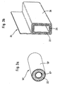
- FIG. 3a shows a cross section in perspective by a filled according to the inventive method double-walled tube 16 ', which consists of an inner tube 17' and an outer tube arranged essentially concentrically thereto 18 'exists.
- the one located between inner tube 17 'and outer tube 18' completed double wall cavity is with carbon foam 22 filled out, due to the small cross-section of the double-wall cavity, the carbon powder directly was introduced into the cavity without using a foil bag.
- Figure 3b shows a cross section in a perspective view by a profile carrier 24, which by an inner profile 25 and an outer profile 26 formed closed cavity by the process according to the invention with carbon foam 22 is filled in, here too due to the low Cross section the carbon powder directly into the profile cavity was introduced.
Landscapes
- Engineering & Computer Science (AREA)
- Chemical & Material Sciences (AREA)
- Ceramic Engineering (AREA)
- Structural Engineering (AREA)
- Combustion & Propulsion (AREA)
- Mechanical Engineering (AREA)
- Materials Engineering (AREA)
- Organic Chemistry (AREA)
- Transportation (AREA)
- General Engineering & Computer Science (AREA)
- Architecture (AREA)
- Body Structure For Vehicles (AREA)
- Exhaust Silencers (AREA)
- Rigid Pipes And Flexible Pipes (AREA)
- Molding Of Porous Articles (AREA)
- Carbon And Carbon Compounds (AREA)
- Laminated Bodies (AREA)
- Casting Or Compression Moulding Of Plastics Or The Like (AREA)
Abstract
Description
- Figur 1
- zeigt einen Längsschnitt durch ein doppelwandiges Rohr, dessen Hohlräume erfindungsgemäß mit Kohlenstoff-Pulver enthaltenden Beuteln versehen sind.
- Figur 2
- zeigt ein Detail aus einem zwischen zwei Blechen befindlichen Hohlraum, der nach dem erfindungsgemäßen Verfahren auf Distanz ausgeschäumt wird.
- Figuren 3a und 3b
- zeigen Querschnitte erfindungsgemäß ausgeschäumter Werkstücke.
Claims (12)
- Verfahren zum Füllen von Hohlräumen (30) in Werkstücken oder Halbzeugen mit den folgenden Schritten:lagesicheres Einbringen von thermisch aufschäumbarem Kohlenstoff-Pulver (20) in dem zu füllenden Hohlraum (30) des Werkstücks oder Halbzeugs undBeheizen des Kohlenstoff-Pulvers (20) gemeinsam mit dem Werkstück oder Halbzeug derart, daß das Kohlenstoff-Pulver (20) aufquillt und als Kohlenstoff-Schaum (22) den Hohlraum (30) ausfüllt, wobei die Partikel des Kohlenstoff-Pulvers im Anlieferungszustand kleiner sind als nach dem Aufschäumen.
- Verfahren nach Anspruch 1, bei dem das lagesichere Einbringen des Kohlenstoff-Pulvers bei doppelwandigen Werkstücken, insbesondere Rohren (16') und Profilen (24), durch direktes Einfüllen des Kohlenstoff-Pulvers (20) in den Doppelwandungshohlraum erfolgt.
- Verfahren nach Anspruch 1, bei dem das Kohlenstoff-Pulver (20) zum lagesicheren Einbringen in den Hohlraum (30) in verschlossenen Aluminium-Folienbeuteln (10, 11, 12) hermetisch eingeschlossen angeordnet ist.
- Verfahren nach einem der Ansprüche 1 bis 3, bei dem das Beheizen durch einen zur weiteren Bearbeitung des Werkstücks oder Halbzeugs notwendigen Arbeitsvorgang erfolgt.
- Verfahren nach Anspruch 4, bei dem zum Füllen von Karosseriehohlräumen das Kohlenstoff-Pulver (20) bereits in der Rohbauphase der Karosserie in die Hohlräume (30) eingebracht wird, mit der Karosserie eine Tauchlackierung durchläuft und das Aufschäumen gemeinsam mit dem Einbrennen des Tauchlacks erfolgt.
- Verfahren nach einem der Ansprüche 1 bis 3, bei dem das Beheizen durch die Inbetriebnahme der bestimmungsgemäßen Verwendung des Werkstücks erfolgt.
- Verfahren nach Anspruch 6, bei dem zum Füllen von Doppelwandungshohlräumen eines doppelwandigen Auspuffrohres (16') das Kohlenstoff-Pulver (20) vor der Endmontage in die zu füllenden Doppelwandungshohlräume eingebracht wird und das Aufschäumen beim ersten Erreichen der Betriebstemperatur des Auspuffrohres (16') erfolgt.
- Bauelement, insbesondere Werkstück oder Halbzeug, zum An- oder Einbau in ein Kraftfahrzeug, mit mindestens einem Hohlraum (30), in den thermisch aufschäumbares Kohlenstoff-Pulver (20) lagesicher eingebracht ist, wobei zum Aufquellen des Kohlenstoff-Pulvers (20) zur Bildung von den Hohlraum (30) ausfüllendem Kohlenstoff-Schaum (22) ein Beheizen des Kohlenstoff-Pulvers (20) gemeinsam mit dem Bauelement erfolgt und wobei die Partikel des Kohlenstoff-Pulvers im Anlieferungszustand kleiner sind als nach dem Aufschäumen.
- Bauelement nach Anspruch 8, bei dem das Beheizen durch die Inbetriebnahme der bestimmungsgemäßen Verwendung des Bauelements erfolgt.
- Bauelement nach Anspruch 9, bei dem das Bauelement ein doppelwandiges, insbesondere abgasführendes Rohr (16') mit direkt in den Doppelwandungshohlraum eingefülltem Kohlenstoff-Pulver (20) ist, und bei dem das Aufschäumen beim ersten Erreichen der Betriebstemperatur des Rohres (16') erfolgt.
- Bauelement nach Anspruch 8, bei dem das Bauelement ein Profilträger (24) mit lagesicher in den mindestens einen Hohlraum (30) angeordneten, hermetisch eingeschlossenes Kohlenstoff-Pulver (20) beinhaltenden Aluminium-Folienbeuteln (10, 11, 12) ist.
- Bauelement nach Anspruch 11, bei dem die Kohlenstoff-Pulver (20) beinhaltenden Aluminium-Folienbeutel (10, 11, 12) bereits vor oder in der Rohbauphase der Karosserie in den mindestens einen Hohlraum (30) eingebracht sind, um mit der Karosserie eine Tauchlackierung zu durchlaufen, so daß das Aufschäumen gemeinsam mit dem Einbrennen des Tauchlacks erfolgt.
Applications Claiming Priority (2)
| Application Number | Priority Date | Filing Date | Title |
|---|---|---|---|
| DE19727907 | 1997-07-01 | ||
| DE19727907A DE19727907C2 (de) | 1997-07-01 | 1997-07-01 | Verfahren zum Füllen von Doppelwandungshohlräumen eines Doppelwandigenauspuffrohres und doppelwandiges, insbesondere abgasführendes Rohr |
Publications (2)
| Publication Number | Publication Date |
|---|---|
| EP0889012A1 true EP0889012A1 (de) | 1999-01-07 |
| EP0889012B1 EP0889012B1 (de) | 2001-10-10 |
Family
ID=7834198
Family Applications (1)
| Application Number | Title | Priority Date | Filing Date |
|---|---|---|---|
| EP98111284A Expired - Lifetime EP0889012B1 (de) | 1997-07-01 | 1998-06-18 | Verfahren zum Füllen von Hohlräumen in Werkstücken oder Halbzeugen und Bauelement zum An- oder Einbau in ein Kraftfahrzeug |
Country Status (5)
| Country | Link |
|---|---|
| US (1) | US6152260A (de) |
| EP (1) | EP0889012B1 (de) |
| JP (1) | JP3191153B2 (de) |
| DE (2) | DE19727907C2 (de) |
| ES (1) | ES2165645T3 (de) |
Cited By (1)
| Publication number | Priority date | Publication date | Assignee | Title |
|---|---|---|---|---|
| WO2001024989A1 (en) * | 1999-10-04 | 2001-04-12 | Tyco Electronics Corporation | Cavity sealing article with articulated support |
Families Citing this family (31)
| Publication number | Priority date | Publication date | Assignee | Title |
|---|---|---|---|---|
| US6103341A (en) | 1997-12-08 | 2000-08-15 | L&L Products | Self-sealing partition |
| US6131897A (en) | 1999-03-16 | 2000-10-17 | L & L Products, Inc. | Structural reinforcements |
| US6358584B1 (en) | 1999-10-27 | 2002-03-19 | L&L Products | Tube reinforcement with deflecting wings and structural foam |
| US6668457B1 (en) | 1999-12-10 | 2003-12-30 | L&L Products, Inc. | Heat-activated structural foam reinforced hydroform |
| US6467834B1 (en) | 2000-02-11 | 2002-10-22 | L&L Products | Structural reinforcement system for automotive vehicles |
| CA2399457C (en) | 2000-02-11 | 2009-09-15 | L&L Products, Inc. | Structural reinforcement system for automotive vehicles |
| DE10008461A1 (de) * | 2000-02-23 | 2001-08-30 | Fritzmeier Georg Gmbh & Co | Faserverbundformteil |
| US6296298B1 (en) | 2000-03-14 | 2001-10-02 | L&L Products, Inc. | Structural reinforcement member for wheel well |
| US6422575B1 (en) | 2000-03-14 | 2002-07-23 | L&L Products, Inc. | Expandable pre-formed plug |
| US6482486B1 (en) | 2000-03-14 | 2002-11-19 | L&L Products | Heat activated reinforcing sleeve |
| US6321793B1 (en) | 2000-06-12 | 2001-11-27 | L&L Products | Bladder system for reinforcing a portion of a longitudinal structure |
| US6820923B1 (en) * | 2000-08-03 | 2004-11-23 | L&L Products | Sound absorption system for automotive vehicles |
| US6561571B1 (en) | 2000-09-29 | 2003-05-13 | L&L Products, Inc. | Structurally enhanced attachment of a reinforcing member |
| US6471285B1 (en) | 2000-09-29 | 2002-10-29 | L&L Products, Inc. | Hydroform structural reinforcement system |
| US7169344B2 (en) * | 2002-04-26 | 2007-01-30 | L&L Products, Inc. | Method of reinforcing at least a portion of a structure |
| US7513564B2 (en) * | 2003-07-01 | 2009-04-07 | Honda Motor Co., Ltd. | Skeleton structural member for transportation equipment |
| US8381403B2 (en) | 2005-05-25 | 2013-02-26 | Zephyros, Inc. | Baffle for an automotive vehicle and method of use therefor |
| US20070028432A1 (en) * | 2005-08-03 | 2007-02-08 | Alcoa, Inc. | Apparatus and method for separating composite panels into metal skins and polymer cores |
| US7784185B2 (en) * | 2006-01-09 | 2010-08-31 | Murray Scott L | Foam wheel cladding process |
| FR2906307B1 (fr) * | 2006-09-26 | 2008-12-19 | Faurecia Sys Echappement | Dispositif d'echappement des gaz emanant d'un moteur a combustion interne de vehicule automobile. |
| JP4809172B2 (ja) * | 2006-09-27 | 2011-11-09 | イイダ産業株式会社 | 発泡充填具、及びそれを用いた発泡体の充填方法 |
| FR2917046B1 (fr) * | 2007-06-11 | 2009-12-18 | Peugeot Citroen Automobiles Sa | "element de structure a caracteristique anti-bruit d'un vehicule automobile" |
| DE102007053964A1 (de) | 2007-07-18 | 2009-01-22 | Johnson Controls Gmbh | Struktur für einen Fahrzeugsitz |
| DE102007053961A1 (de) | 2007-07-18 | 2009-01-22 | Johnson Controls Gmbh | Struktur für einen Fahrzeugsitz |
| RU2521824C2 (ru) * | 2008-07-30 | 2014-07-10 | Эрсель | Узел из элементов, соединенных посредством устройства, обеспечивающего целостность поверхности одного из элементов |
| GB2500638A (en) * | 2012-03-28 | 2013-10-02 | Nissan Motor Mfg Uk Ltd | A vehicle sound insulator |
| JP2014218924A (ja) * | 2013-05-07 | 2014-11-20 | 株式会社神戸製鋼所 | 消音器遮音構造 |
| US9341287B2 (en) * | 2014-02-24 | 2016-05-17 | Lockheed Martin Corporation | Friction stir welded pipes |
| CN104139187A (zh) * | 2014-07-03 | 2014-11-12 | 南通志邦新材料科技有限公司 | 一种降噪音钢管的加工工艺 |
| DE102018202444A1 (de) * | 2018-02-19 | 2019-06-19 | Audi Ag | Verstärkungsmittel und Verfahren zur Hohlraumverstärkung einer Rohbaustruktur |
| DE102023117430A1 (de) | 2023-07-03 | 2025-01-09 | Audi Aktiengesellschaft | Ausschäumvorrichtung mit Aufschäumbeutel zum Ausschäumen eines Hohlraumes eines Karosseriebauteils, Verfahren zum Ausschäumen und Kraftfahrzeug mit ausgeschäumtem Karosseriebauteil |
Citations (7)
| Publication number | Priority date | Publication date | Assignee | Title |
|---|---|---|---|---|
| US4285909A (en) * | 1972-05-13 | 1981-08-25 | Toyota Jidosha Kogyo Kabushiki Kaisha | Catalyst assembly for cleaning an exhaust gas |
| DE3323801A1 (de) * | 1983-07-01 | 1985-01-03 | C. Conradty Nürnberg GmbH & Co KG, 8505 Röthenbach | Verfahren zur herstellung eines schuettfaehigen kohlenstoffmaterials |
| DE3625080A1 (de) * | 1986-07-24 | 1988-01-28 | Lentia Gmbh | Thermisch expandierbare masse, verfahren zu ihrer herstellung und verwendung |
| JPS63247588A (ja) * | 1987-04-03 | 1988-10-14 | 川崎製鉄株式会社 | 高温断熱構造 |
| DE3826011A1 (de) * | 1988-07-30 | 1990-02-01 | Bayerische Motoren Werke Ag | Verfahren und vorrichtung zum ausschaeumen von hohlraeumen, insbesondere einer fahrzeugkarosserie |
| DE4039863C1 (en) * | 1990-12-13 | 1992-02-13 | Bayer Ag, 5090 Leverkusen, De | Insulated double pipe - has nested pipes with foaming heat insulation in between, plus leakage sensor line below inner pipe, screened from insulation by cover film |
| WO1996036660A1 (de) * | 1995-05-20 | 1996-11-21 | Henkel Teroson Gmbh | Heisshärtende geschäumte kautschukmassen mit hoher strukturfestigkeit |
Family Cites Families (16)
| Publication number | Priority date | Publication date | Assignee | Title |
|---|---|---|---|---|
| US3635676A (en) * | 1969-11-05 | 1972-01-18 | Atomic Energy Commission | Method for increasing the strength of carbon foam |
| NL8602548A (nl) * | 1985-10-24 | 1987-05-18 | Dow Corning | Werkwijze voor het verschaffen van een geschuimde massa in een holte. |
| US4734323A (en) * | 1986-04-22 | 1988-03-29 | Toyoda Gosei Co., Ltd. | Vibration damping soundproof sheets for use in vehicles |
| JPS6354217A (ja) * | 1986-08-25 | 1988-03-08 | Toyota Motor Corp | 発泡体の充填方法 |
| DE8715142U1 (de) * | 1987-11-13 | 1988-06-01 | Dr. Alois Stankiewicz GmbH, 3101 Adelheidsdorf | Schalldämmteil mit Absorptionseigenschaften für Trennwand |
| DE3826012A1 (de) * | 1988-07-30 | 1990-02-01 | Bayerische Motoren Werke Ag | Verfahren und schaumstoff-koerper zur abschottung von hohlkoerpern |
| DE4038979A1 (de) * | 1989-12-07 | 1991-06-13 | Vw Werke Vincenz Wiederholt Gm | Doppelrohr, insbesondere fuer katalysatorbestueckte abgasanlagen von brennkraftmaschinen und verfahren zur herstellung eines solchen doppelrohres |
| DE4007075A1 (de) * | 1990-03-07 | 1991-09-12 | Bayer Ag | Intumeszenzfaehige formteile |
| DE4016710A1 (de) * | 1990-05-24 | 1991-11-28 | Bayer Ag | Verfahren zur herstellung von formteilen |
| EP0542852B1 (de) * | 1990-08-08 | 1994-10-12 | Exxon Chemical Patents Inc. | Verfahren zur herstellung von geformten expandierbaren teilen |
| DE4028895C1 (en) * | 1990-09-12 | 1992-02-20 | Mercedes-Benz Aktiengesellschaft, 7000 Stuttgart, De | Foamed component made of elastic, flexible plastic - used for sound insulation, consists of hollow chassis into which polyurethane foam unit is adhered inside and unit is seated |
| DE4227393C2 (de) * | 1991-08-31 | 2001-05-10 | Volkswagen Ag | Träger mit einem metallenen Hohlkörper und einem Kern |
| JP3248230B2 (ja) * | 1992-03-31 | 2002-01-21 | 東海ゴム工業株式会社 | 中空部材への発泡体の充填方法 |
| ATA129392A (de) * | 1992-06-25 | 1999-02-15 | Greiner & Soehne C A | Schaumstoffplatte, insbesondere formteil aus einer oder mehreren schaumstoffplatten |
| JPH0788874A (ja) * | 1993-07-29 | 1995-04-04 | Asahi Chem Ind Co Ltd | 中空構造体内部を発泡体で充填する方法 |
| JPH07232665A (ja) * | 1994-02-24 | 1995-09-05 | Nippon Tokushu Toryo Co Ltd | 自動車の防音処理工法 |
-
1997
- 1997-07-01 DE DE19727907A patent/DE19727907C2/de not_active Expired - Fee Related
-
1998
- 1998-06-18 ES ES98111284T patent/ES2165645T3/es not_active Expired - Lifetime
- 1998-06-18 EP EP98111284A patent/EP0889012B1/de not_active Expired - Lifetime
- 1998-06-18 DE DE59801679T patent/DE59801679D1/de not_active Expired - Fee Related
- 1998-06-30 JP JP21953398A patent/JP3191153B2/ja not_active Expired - Fee Related
- 1998-07-01 US US09/108,408 patent/US6152260A/en not_active Expired - Fee Related
Patent Citations (7)
| Publication number | Priority date | Publication date | Assignee | Title |
|---|---|---|---|---|
| US4285909A (en) * | 1972-05-13 | 1981-08-25 | Toyota Jidosha Kogyo Kabushiki Kaisha | Catalyst assembly for cleaning an exhaust gas |
| DE3323801A1 (de) * | 1983-07-01 | 1985-01-03 | C. Conradty Nürnberg GmbH & Co KG, 8505 Röthenbach | Verfahren zur herstellung eines schuettfaehigen kohlenstoffmaterials |
| DE3625080A1 (de) * | 1986-07-24 | 1988-01-28 | Lentia Gmbh | Thermisch expandierbare masse, verfahren zu ihrer herstellung und verwendung |
| JPS63247588A (ja) * | 1987-04-03 | 1988-10-14 | 川崎製鉄株式会社 | 高温断熱構造 |
| DE3826011A1 (de) * | 1988-07-30 | 1990-02-01 | Bayerische Motoren Werke Ag | Verfahren und vorrichtung zum ausschaeumen von hohlraeumen, insbesondere einer fahrzeugkarosserie |
| DE4039863C1 (en) * | 1990-12-13 | 1992-02-13 | Bayer Ag, 5090 Leverkusen, De | Insulated double pipe - has nested pipes with foaming heat insulation in between, plus leakage sensor line below inner pipe, screened from insulation by cover film |
| WO1996036660A1 (de) * | 1995-05-20 | 1996-11-21 | Henkel Teroson Gmbh | Heisshärtende geschäumte kautschukmassen mit hoher strukturfestigkeit |
Non-Patent Citations (1)
| Title |
|---|
| CHEMICAL ABSTRACTS, vol. 110, no. 16, 17 April 1989, Columbus, Ohio, US; abstract no. 140411z, S. TAKAHASHI, ET AL page 329; XP000058885 * |
Cited By (1)
| Publication number | Priority date | Publication date | Assignee | Title |
|---|---|---|---|---|
| WO2001024989A1 (en) * | 1999-10-04 | 2001-04-12 | Tyco Electronics Corporation | Cavity sealing article with articulated support |
Also Published As
| Publication number | Publication date |
|---|---|
| US6152260A (en) | 2000-11-28 |
| DE19727907A1 (de) | 1998-05-14 |
| JP3191153B2 (ja) | 2001-07-23 |
| EP0889012B1 (de) | 2001-10-10 |
| JPH11165327A (ja) | 1999-06-22 |
| DE19727907C2 (de) | 1999-10-14 |
| ES2165645T3 (es) | 2002-03-16 |
| DE59801679D1 (de) | 2001-11-15 |
Similar Documents
| Publication | Publication Date | Title |
|---|---|---|
| EP0889012B1 (de) | Verfahren zum Füllen von Hohlräumen in Werkstücken oder Halbzeugen und Bauelement zum An- oder Einbau in ein Kraftfahrzeug | |
| DE19653509B4 (de) | Rahmenstruktur einer Fahrzeugkarosserie aus Knotenelementen und angeschlossenen, vorprofilierten Trägerelementen | |
| EP1373053B1 (de) | Vorrichtung zur verstärkung eines hohlteils eines fahrzeugs | |
| DE4203460C2 (de) | Verfahren zum Herstellen eines trägerartigen Bauteils mit einem Leichtstoffkern | |
| DE60016241T2 (de) | Verstärkter durch innenhochdruck geformter gegenstand und verfahren zur herstellung | |
| DE69822483T3 (de) | Lasttragendes fahrzeugdach und verfahren zu seiner herstellung | |
| DE102007062524B3 (de) | Verfahren zur Herstellung eines Hybridbauteils und Hybridbauteil | |
| DE4028895C1 (en) | Foamed component made of elastic, flexible plastic - used for sound insulation, consists of hollow chassis into which polyurethane foam unit is adhered inside and unit is seated | |
| EP1256512B1 (de) | Verstärkungselement für einen Hohlkörper, insbesondere für einen Fahrzeugkarosserieholm | |
| DE19538844A1 (de) | Karosserie-Seitenteil für ein Kraftfahrzeug | |
| EP2181016A1 (de) | Struktur für einen fahrzeugsitz | |
| EP0760329A2 (de) | Seitenwandbaugruppe für eine Kraftfahrzeugkarosserie | |
| DE19714631A1 (de) | Selbsttragende Kraftfahrzeugkarosserie | |
| DE10024004C2 (de) | Verfahren zur Herstellung eines Bauteils aus Verbundwerkstoff | |
| EP2181018A1 (de) | Struktur für einen fahrzeugsitz | |
| DE102006054208B4 (de) | Behälter für Betriebsstoffe von Kraftfahrzeugen | |
| WO2011144427A1 (de) | Verfahren zum herstellen eines hohlprofils | |
| WO2008095691A1 (de) | Verfahren zur herstellung eines verbundkörpers und zwischenprodukt zur herstellung eines verbundkörpers | |
| DE102013022247B4 (de) | Fahrzeug-Karosserieelement | |
| DE102015100968A1 (de) | Verfahren zur Herstellung einer Kraftfahrzeugkarosserie in Mischbauweise | |
| EP0287941A1 (de) | Verfahren zum Versteifen des metallischen Chassis, insbesondere der Bodengruppe von Personenkraftwagen | |
| DE4425984A1 (de) | Verfahren zum Herstellen eines hohlen Bauteils aus Metall | |
| DE19911213C1 (de) | Verbundbauteil und Verfahren zur Herstellung des Verbundbauteiles | |
| EP1257459B1 (de) | Hilfsrahmen eines kraftfahrzeugfahrwerks | |
| DE102014208835A1 (de) | Verfahren zur Herstellung eines Kunststoffbauteils |
Legal Events
| Date | Code | Title | Description |
|---|---|---|---|
| PUAI | Public reference made under article 153(3) epc to a published international application that has entered the european phase |
Free format text: ORIGINAL CODE: 0009012 |
|
| 17P | Request for examination filed |
Effective date: 19981029 |
|
| AK | Designated contracting states |
Kind code of ref document: A1 Designated state(s): DE ES FR GB IT SE |
|
| AX | Request for extension of the european patent |
Free format text: AL;LT;LV;MK;RO;SI |
|
| RAP1 | Party data changed (applicant data changed or rights of an application transferred) |
Owner name: DAIMLERCHRYSLER AG |
|
| AKX | Designation fees paid |
Free format text: DE ES FR GB IT SE |
|
| 17Q | First examination report despatched |
Effective date: 20000413 |
|
| GRAG | Despatch of communication of intention to grant |
Free format text: ORIGINAL CODE: EPIDOS AGRA |
|
| GRAG | Despatch of communication of intention to grant |
Free format text: ORIGINAL CODE: EPIDOS AGRA |
|
| GRAH | Despatch of communication of intention to grant a patent |
Free format text: ORIGINAL CODE: EPIDOS IGRA |
|
| GRAH | Despatch of communication of intention to grant a patent |
Free format text: ORIGINAL CODE: EPIDOS IGRA |
|
| GRAA | (expected) grant |
Free format text: ORIGINAL CODE: 0009210 |
|
| ITF | It: translation for a ep patent filed | ||
| AK | Designated contracting states |
Kind code of ref document: B1 Designated state(s): DE ES FR GB IT SE |
|
| REF | Corresponds to: |
Ref document number: 59801679 Country of ref document: DE Date of ref document: 20011115 |
|
| REG | Reference to a national code |
Ref country code: GB Ref legal event code: IF02 |
|
| GBT | Gb: translation of ep patent filed (gb section 77(6)(a)/1977) |
Effective date: 20020111 |
|
| ET | Fr: translation filed | ||
| REG | Reference to a national code |
Ref country code: ES Ref legal event code: FG2A Ref document number: 2165645 Country of ref document: ES Kind code of ref document: T3 |
|
| PGFP | Annual fee paid to national office [announced via postgrant information from national office to epo] |
Ref country code: SE Payment date: 20020531 Year of fee payment: 5 |
|
| PLBE | No opposition filed within time limit |
Free format text: ORIGINAL CODE: 0009261 |
|
| STAA | Information on the status of an ep patent application or granted ep patent |
Free format text: STATUS: NO OPPOSITION FILED WITHIN TIME LIMIT |
|
| 26N | No opposition filed | ||
| PG25 | Lapsed in a contracting state [announced via postgrant information from national office to epo] |
Ref country code: SE Free format text: LAPSE BECAUSE OF NON-PAYMENT OF DUE FEES Effective date: 20030619 |
|
| EUG | Se: european patent has lapsed | ||
| PGFP | Annual fee paid to national office [announced via postgrant information from national office to epo] |
Ref country code: GB Payment date: 20050606 Year of fee payment: 8 |
|
| PGFP | Annual fee paid to national office [announced via postgrant information from national office to epo] |
Ref country code: FR Payment date: 20050610 Year of fee payment: 8 |
|
| PGFP | Annual fee paid to national office [announced via postgrant information from national office to epo] |
Ref country code: DE Payment date: 20050613 Year of fee payment: 8 |
|
| PGFP | Annual fee paid to national office [announced via postgrant information from national office to epo] |
Ref country code: ES Payment date: 20050615 Year of fee payment: 8 |
|
| PG25 | Lapsed in a contracting state [announced via postgrant information from national office to epo] |
Ref country code: GB Free format text: LAPSE BECAUSE OF NON-PAYMENT OF DUE FEES Effective date: 20060618 |
|
| PG25 | Lapsed in a contracting state [announced via postgrant information from national office to epo] |
Ref country code: ES Free format text: LAPSE BECAUSE OF NON-PAYMENT OF DUE FEES Effective date: 20060619 |
|
| PGFP | Annual fee paid to national office [announced via postgrant information from national office to epo] |
Ref country code: IT Payment date: 20060630 Year of fee payment: 9 |
|
| PG25 | Lapsed in a contracting state [announced via postgrant information from national office to epo] |
Ref country code: DE Free format text: LAPSE BECAUSE OF NON-PAYMENT OF DUE FEES Effective date: 20070103 |
|
| GBPC | Gb: european patent ceased through non-payment of renewal fee |
Effective date: 20060618 |
|
| REG | Reference to a national code |
Ref country code: FR Ref legal event code: ST Effective date: 20070228 |
|
| REG | Reference to a national code |
Ref country code: ES Ref legal event code: FD2A Effective date: 20060619 |
|
| PG25 | Lapsed in a contracting state [announced via postgrant information from national office to epo] |
Ref country code: FR Free format text: LAPSE BECAUSE OF NON-PAYMENT OF DUE FEES Effective date: 20060630 |
|
| PG25 | Lapsed in a contracting state [announced via postgrant information from national office to epo] |
Ref country code: IT Free format text: LAPSE BECAUSE OF NON-PAYMENT OF DUE FEES Effective date: 20070618 |