EP0889280A1 - Scheinwerfer für Kraftfahrzeuge, der zwei verschiedene Lichtverteilungsmuster mit einer einzigen Lichtquelle erzeugen kann - Google Patents
Scheinwerfer für Kraftfahrzeuge, der zwei verschiedene Lichtverteilungsmuster mit einer einzigen Lichtquelle erzeugen kann Download PDFInfo
- Publication number
- EP0889280A1 EP0889280A1 EP98401613A EP98401613A EP0889280A1 EP 0889280 A1 EP0889280 A1 EP 0889280A1 EP 98401613 A EP98401613 A EP 98401613A EP 98401613 A EP98401613 A EP 98401613A EP 0889280 A1 EP0889280 A1 EP 0889280A1
- Authority
- EP
- European Patent Office
- Prior art keywords
- mirror
- axis
- source
- projector according
- zone
- Prior art date
- Legal status (The legal status is an assumption and is not a legal conclusion. Google has not performed a legal analysis and makes no representation as to the accuracy of the status listed.)
- Withdrawn
Links
- 238000006073 displacement reaction Methods 0.000 claims description 4
- BASFCYQUMIYNBI-UHFFFAOYSA-N platinum Chemical compound [Pt] BASFCYQUMIYNBI-UHFFFAOYSA-N 0.000 description 4
- 230000000875 corresponding effect Effects 0.000 description 3
- 230000000694 effects Effects 0.000 description 3
- 230000035939 shock Effects 0.000 description 3
- 238000005375 photometry Methods 0.000 description 2
- 241001080024 Telles Species 0.000 description 1
- 230000009471 action Effects 0.000 description 1
- 230000033228 biological regulation Effects 0.000 description 1
- 230000005540 biological transmission Effects 0.000 description 1
- 230000015572 biosynthetic process Effects 0.000 description 1
- 230000000295 complement effect Effects 0.000 description 1
- 230000001276 controlling effect Effects 0.000 description 1
- 230000036461 convulsion Effects 0.000 description 1
- 230000002596 correlated effect Effects 0.000 description 1
- 230000008034 disappearance Effects 0.000 description 1
- 230000008020 evaporation Effects 0.000 description 1
- 238000001704 evaporation Methods 0.000 description 1
- 229910052736 halogen Inorganic materials 0.000 description 1
- 150000002367 halogens Chemical class 0.000 description 1
- 238000005286 illumination Methods 0.000 description 1
- 230000007246 mechanism Effects 0.000 description 1
- 230000004048 modification Effects 0.000 description 1
- 238000012986 modification Methods 0.000 description 1
- 150000003839 salts Chemical class 0.000 description 1
- 241000894007 species Species 0.000 description 1
- 230000003068 static effect Effects 0.000 description 1
- 230000000007 visual effect Effects 0.000 description 1
Images
Classifications
-
- B—PERFORMING OPERATIONS; TRANSPORTING
- B60—VEHICLES IN GENERAL
- B60Q—ARRANGEMENT OF SIGNALLING OR LIGHTING DEVICES, THE MOUNTING OR SUPPORTING THEREOF OR CIRCUITS THEREFOR, FOR VEHICLES IN GENERAL
- B60Q1/00—Arrangement of optical signalling or lighting devices, the mounting or supporting thereof or circuits therefor
- B60Q1/02—Arrangement of optical signalling or lighting devices, the mounting or supporting thereof or circuits therefor the devices being primarily intended to illuminate the way ahead or to illuminate other areas of way or environments
- B60Q1/04—Arrangement of optical signalling or lighting devices, the mounting or supporting thereof or circuits therefor the devices being primarily intended to illuminate the way ahead or to illuminate other areas of way or environments the devices being headlights
- B60Q1/14—Arrangement of optical signalling or lighting devices, the mounting or supporting thereof or circuits therefor the devices being primarily intended to illuminate the way ahead or to illuminate other areas of way or environments the devices being headlights having dimming means
- B60Q1/1415—Dimming circuits
-
- B—PERFORMING OPERATIONS; TRANSPORTING
- B60—VEHICLES IN GENERAL
- B60Q—ARRANGEMENT OF SIGNALLING OR LIGHTING DEVICES, THE MOUNTING OR SUPPORTING THEREOF OR CIRCUITS THEREFOR, FOR VEHICLES IN GENERAL
- B60Q1/00—Arrangement of optical signalling or lighting devices, the mounting or supporting thereof or circuits therefor
- B60Q1/02—Arrangement of optical signalling or lighting devices, the mounting or supporting thereof or circuits therefor the devices being primarily intended to illuminate the way ahead or to illuminate other areas of way or environments
- B60Q1/04—Arrangement of optical signalling or lighting devices, the mounting or supporting thereof or circuits therefor the devices being primarily intended to illuminate the way ahead or to illuminate other areas of way or environments the devices being headlights
- B60Q1/06—Arrangement of optical signalling or lighting devices, the mounting or supporting thereof or circuits therefor the devices being primarily intended to illuminate the way ahead or to illuminate other areas of way or environments the devices being headlights adjustable, e.g. remotely-controlled from inside vehicle
- B60Q1/076—Arrangement of optical signalling or lighting devices, the mounting or supporting thereof or circuits therefor the devices being primarily intended to illuminate the way ahead or to illuminate other areas of way or environments the devices being headlights adjustable, e.g. remotely-controlled from inside vehicle by electrical means including means to transmit the movements, e.g. shafts or joints
-
- F—MECHANICAL ENGINEERING; LIGHTING; HEATING; WEAPONS; BLASTING
- F21—LIGHTING
- F21S—NON-PORTABLE LIGHTING DEVICES; SYSTEMS THEREOF; VEHICLE LIGHTING DEVICES SPECIALLY ADAPTED FOR VEHICLE EXTERIORS
- F21S41/00—Illuminating devices specially adapted for vehicle exteriors, e.g. headlamps
- F21S41/30—Illuminating devices specially adapted for vehicle exteriors, e.g. headlamps characterised by reflectors
- F21S41/32—Optical layout thereof
- F21S41/33—Multi-surface reflectors, e.g. reflectors with facets or reflectors with portions of different curvature
- F21S41/334—Multi-surface reflectors, e.g. reflectors with facets or reflectors with portions of different curvature the reflector consisting of patch like sectors
-
- F—MECHANICAL ENGINEERING; LIGHTING; HEATING; WEAPONS; BLASTING
- F21—LIGHTING
- F21S—NON-PORTABLE LIGHTING DEVICES; SYSTEMS THEREOF; VEHICLE LIGHTING DEVICES SPECIALLY ADAPTED FOR VEHICLE EXTERIORS
- F21S41/00—Illuminating devices specially adapted for vehicle exteriors, e.g. headlamps
- F21S41/60—Illuminating devices specially adapted for vehicle exteriors, e.g. headlamps characterised by a variable light distribution
- F21S41/67—Illuminating devices specially adapted for vehicle exteriors, e.g. headlamps characterised by a variable light distribution by acting on reflectors
- F21S41/675—Illuminating devices specially adapted for vehicle exteriors, e.g. headlamps characterised by a variable light distribution by acting on reflectors by moving reflectors
Definitions
- the present invention relates generally motor vehicle headlamps, and relates in especially a capable projector, with a single lamp and a single reflector, to generate two beams different bright.
- document DE-A-44 19 365 describes a projector whose mirror has a movable part, the lamp being fixed, and the displacement of this part mobile allows the photometric distribution of the beam, and thus to generate two different beams.
- FR-A-2 239 862 a projector in which one carries out a translation combined lamp, vertically and horizontally, compared to a fixed reflector, together with a tilting of a concealer associated with the lamp, to selectively generate a passing beam or a road beam.
- the shocks to which the lamp is subjected upon each movement, and particular at each arrival at the end of the race decrease significantly its lifespan. This lifespan is also reduced by the vibrations to which the lamp is exposed. Indeed, the required speed of movement especially to pass in the times imposed by the rules between the crossover function and the function road implies that the lamp is mounted on a crew mobile as light as possible, with consequent almost impossible to filter these vibrations.
- the document CH-176 477-A describes a projector in which a reflector is pivotally mounted relative to the lamp, around a horizontal axis passing through the focal point of the reflector and filament of the lamp.
- the present invention aims to overcome these disadvantages of the state of the art.
- a vehicle headlamp automobile comprising a light source and a mirror movable relative to each other to generate two light beams of different types, the source light being fixedly mounted on a part of the projector with respect to which the mirror can be moved for selectively occupy one of two positions discrete, the displacement of the mirror relative to the source consisting of a tilting around an axis, in which the axis is distant from the source.
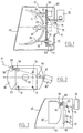
- FIG. 1 shows a vehicle headlight automobile which, conventionally, has a housing 10 closed at the front by a window 40 and housing a lamp 20 and a reflector or mirror 30 provided with a hole 33 for the lamp 20.
- the housing 10 also has, at the rear, a lamp access opening 20, closed by a cap 11.
- a lamp and mirror support plate 50 In the interior of the housing 10 is provided a lamp and mirror support plate 50, under generally vertical plate and perpendicular to the general direction x-x emission of the light.
- This plate 50 rests on the rear region of the box in three points arranged at the three vertices of a right triangle, two of which are visible in the figure 1.
- a first of these points is a defined fixed point by a spherical head 13 formed at the free end a rod 12 fixed to the housing in its lower region.
- a third point is found at the height of the first point, and can consist of a manually adjustable spherical head to ensure an azimuth adjustment of the orientation of the beams.
- the plate 50 is mounted on the heads 13, 72 by seats, respectively 53, 52, in which these heads are snapped in, conventionally, and is mounted in the same way on the third head.
- the lamp 20 which is constituted in this case by a discharge lamp comprising a bulb 21 and a base 22, is mounted on plate 50.
- the mirror 30 is also mounted on the plate 50, movably in translation. More specifically, a electric actuator 60 with two stable positions is fixed on the back of the plate 50, in its upper part, and has a translatable outlet rod 61 directed towards the back of the mirror 30 and the free end of which bears a spherical head 62 engaged by snap-fastening in a seat 63 secured to the mirror.
- a device for guiding the mirror in translation constituted by a through guide 51 formed in the plate and through which can slide horizontally a smooth rod 31 secured to the mirror.
- At least one other similar guide device is provided in another place in the mirror, so illustrated.
- the actuator 60 is capable of selectively bringing the mirror 30 into a position moved back, illustrated in solid lines, or in a position advanced, illustrated in dashed lines and whose offset horizontal to the retracted position has been exaggerated for the sake of clarity.
- the light source in the arc of the discharge lamp 20, is positioned relative to the mirror 30 so as to generate a beam light whose light distribution and outline correspond to a European passing beam standardized.
- the device 70 for adjusting site is in a position such as the cut off this beam is at the height imposed by the regulations.
- the translation indicated above allows to generate a defocus of the light source relative to the mirror, which has the main effect of attenuating very substantially the clean cut obtained in the position moved away from the mirror, and to ensure a homogeneous distribution light in an extended horizontal band but relatively thin.
- the tilting of the mirror allows meanwhile to raise all of the light as well distributed, so that the beam is emitted at height suitable for the road.
- a photometry road beam satisfactory is achieved by moving the mirror towards the front over a distance of about 2 mm.
- the site adjustment device 70 As for the importance of the upward tilting performed by the site adjustment device 70, it is preferably of the order of 1 to 2%.
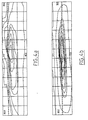
- Figures 4a and 4b show, by sets of isocandela curves on a graduated projection screen in inches, the shape of the passing beam and the driving beam, respectively.
- the site adjustment device 70 has on the one hand the function consisting in carrying out a predetermined tilting of the plate 50 for the passage from one beam to another, and on the other hand the function of beam adjustment in elevation, statically and / or dynamic, depending on variations in attitude of the vehicle, with appropriate superimposition of signals control.
- the device 70 can however, in variant, fill only the first of these functions.
- FIGS. 2 and 3 illustrate a form of realization of the invention.
- the passage from driving beam and conversely, using a single actuator 60 '.
- the mirror 30 is pivotally mounted on the plate 50, around an axis A preferably oriented in oblique and arranged in the upper part of the mirror.
- this axis is materialized by two bearings 54 integral with the plate 50, one of which is crossed by a pivot shaft 34 projecting from from a rear extension 35 of the mirror 30.
- the actuator 60 ' is placed on the axis A, being fixedly mounted on an extension (not shown) of plate 50, and has a rotary output shaft 61 which commands directly, by means of transmission not shown, tilting of the mirror 30.
- the angle between axis A and the horizontal plane is advantageously between 10 and 40 °.
- the axis of the mirror will be shifted to the right, which is suitable in the case of a traffic direction left.
- a single actuator allows to pass, with a fixed lamp, from a mirror position corresponding to a passing beam at a mirror position corresponding to a driving beam, and this without that no other provision is necessary.
- the plate 50 remains mounted on three support points 13, 14 and 72, so as to carry out share, by the device 70, a dynamic correction or static on site, and on the other hand, by manual adjustment level of point 14, an initial azimuth setting.
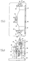
- Figures 5 and 6 schematically illustrate a mechanism for translating the mirror 30 as described with reference to Figure 1.
- the plate includes in this case a base horizontal 90 comprising two lateral uprights 91 to from which two guide fingers 92 protrude, 93 offset in height.
- control bar 100 comprising two oblong slots 102, 103 receiving sliding fingers 92, 93 respectively vertical.
- Each bar 100 generally vertical, has a slightly oblique intermediate part which is trapped between two fingers 81, 82 which are mounted on a frame 80 free relative to the base 100.
- the mirror 30 is mounted on the frame elements 80 via a front flange 36 of the mirror, having fittings 37 projecting towards rear (to the left in Figure 5) on which are fixed the frame elements 80.
- the lamp 20 is fixed on a post 95 extending upwards from base 90, at the bottom from the mirror.
- the mirror was designed so that its part which determines the cut of the beam crossover is defocused from the source bright when the mirror is brought into position road, so as to remove this cut.
- a particular area of the mirror is generally defocused from the source in the crossover position, and on the contrary be refocused in the road position. This allows, using this particular area, to give the road beam the central focus spot necessary for good visual comfort.
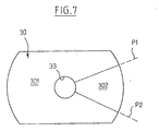
- the mirror 30 illustrated in FIG. 7 comprises a zone 301 and a zone 302, the zone 302 extending, in front view, to the right of the lamp and being delimited in the species by two half-planes P1 and P2 passing from preferably by the axis of the mirror.
- This zone 302 extends for example over 50 to 90 °, while the zone 301 extends for example over 270 to 310 °.
- Zone 301 is suitable, in the position of crossing, to cooperate with the source to generate a beam delimited by a clear cut, in this case a European standard cut-off.
- zone 302 In this same position, zone 302 generates a relatively high level of illumination concentrated, slightly shifted to the right with respect to the axis of the road.
- zone 301 is defocused to diffuse the light emitted, and particular to remove the cut, while zone 302 is refocused, that is to say that the or the outbreaks in this zone 302 are close to the source, so as to emit a more concentrated light, the new orientation of the mirror in this position being such that this concentrated light is emitted in the axis of the road.
- the position and size of the zone 302 can vary widely depending on the type of lamp used. So, especially with a discharge lamp conventionally equipped with opaque strips intended for facilitate the formation of the standardized cutoff, the inclination of the limit plane P2 is not necessarily correlated to the inclination of a cutting part tilted.
- the invention allows not only code / route headlights, but also other types of projectors, including fog light / complementary, etc.
Landscapes
- Engineering & Computer Science (AREA)
- Mechanical Engineering (AREA)
- General Engineering & Computer Science (AREA)
- Non-Portable Lighting Devices Or Systems Thereof (AREA)
- Lighting Device Outwards From Vehicle And Optical Signal (AREA)
Applications Claiming Priority (6)
| Application Number | Priority Date | Filing Date | Title |
|---|---|---|---|
| FR9708192A FR2765308B1 (fr) | 1997-06-30 | 1997-06-30 | Projecteur de vehicule automobile capable d'emettre, avec une source lumineuse unique, deux faisceaux differents |
| FR9708192 | 1997-06-30 | ||
| FR9711326 | 1997-09-11 | ||
| FR9711326A FR2765309B1 (fr) | 1997-06-30 | 1997-09-11 | Projecteur de vehicule automobile capable d'emettre, avec une source lumineuse unique, deux faisceaux differents |
| FR9802476 | 1998-03-02 | ||
| FR9802476A FR2765310B1 (fr) | 1997-06-30 | 1998-03-02 | Projecteur de vehicule automobile capable d'emettre, avec une source lumineuse unique, deux faisceaux differents |
Publications (1)
| Publication Number | Publication Date |
|---|---|
| EP0889280A1 true EP0889280A1 (de) | 1999-01-07 |
Family
ID=27253342
Family Applications (2)
| Application Number | Title | Priority Date | Filing Date |
|---|---|---|---|
| EP98401614A Expired - Lifetime EP0889281B1 (de) | 1997-06-30 | 1998-06-29 | Scheinwerfer für Kraftfahrzeuge, der zwei verschiedene Lichtverteilungmuster mit einer einzigen Lichtquelle erzeugen kann |
| EP98401613A Withdrawn EP0889280A1 (de) | 1997-06-30 | 1998-06-29 | Scheinwerfer für Kraftfahrzeuge, der zwei verschiedene Lichtverteilungsmuster mit einer einzigen Lichtquelle erzeugen kann |
Family Applications Before (1)
| Application Number | Title | Priority Date | Filing Date |
|---|---|---|---|
| EP98401614A Expired - Lifetime EP0889281B1 (de) | 1997-06-30 | 1998-06-29 | Scheinwerfer für Kraftfahrzeuge, der zwei verschiedene Lichtverteilungmuster mit einer einzigen Lichtquelle erzeugen kann |
Country Status (3)
| Country | Link |
|---|---|
| EP (2) | EP0889281B1 (de) |
| DE (1) | DE69823921D1 (de) |
| FR (1) | FR2765310B1 (de) |
Cited By (2)
| Publication number | Priority date | Publication date | Assignee | Title |
|---|---|---|---|---|
| US7600904B2 (en) | 2006-06-16 | 2009-10-13 | Koito Manufacturing Co., Ltd. | Vehicle headlamp |
| CN110641353A (zh) * | 2019-09-06 | 2020-01-03 | 吉利汽车研究院(宁波)有限公司 | 一种前照灯调节方法及系统 |
Families Citing this family (6)
| Publication number | Priority date | Publication date | Assignee | Title |
|---|---|---|---|---|
| CZ299269B6 (cs) | 2004-03-18 | 2008-06-04 | Visteon Global Technologies, Inc. | Serizovací soustava svetlometu zejména pro motorová vozidla |
| US7810972B2 (en) | 2006-10-13 | 2010-10-12 | Visteon Global Technologies, Inc. | Headlamp assembly having an adjustable light beam direction |
| FR2911826B1 (fr) | 2007-01-30 | 2010-03-12 | Valeo Vision | Dispositif d'eclairage multifonction pour vehicule automobile. |
| JP5029571B2 (ja) * | 2008-10-30 | 2012-09-19 | 市光工業株式会社 | 車両用前照灯 |
| DE102015103623B4 (de) | 2015-03-12 | 2024-12-05 | Hella Autotechnik Nova, S.R.O. | Scheinwerfer für Fahrzeuge |
| CN106240442B (zh) * | 2016-09-05 | 2024-02-02 | 华域视觉科技(上海)有限公司 | 一种电机式光型变换装置的安装结构 |
Citations (7)
| Publication number | Priority date | Publication date | Assignee | Title |
|---|---|---|---|---|
| CH176477A (de) | 1934-08-07 | 1935-04-15 | Risch Werner | Scheinwerfer an Fahrzeugen. |
| FR2239862A1 (en) | 1973-08-01 | 1975-02-28 | Cibie Projecteurs | Full or dipped beam vehicle headlamp - pivotal screen is moved by relative movement of lamp and reflector |
| FR2609146A1 (fr) * | 1986-12-30 | 1988-07-01 | Cibie Projecteurs | Projecteur de vehicule automobile comportant un reflecteur parabolique a fond modifie |
| DE3742191A1 (de) * | 1987-12-12 | 1989-06-22 | Hella Kg Hueck & Co | Abblendbarer fahrzeugscheinwerfer |
| US5142455A (en) * | 1991-06-05 | 1992-08-25 | General Electric Company | Vehicle headlamp in which multiple beams are derived from a single discharge-type light source |
| DE4419365A1 (de) | 1994-06-03 | 1995-12-07 | Bosch Gmbh Robert | Scheinwerfer für Fahrzeuge |
| EP0705730A2 (de) | 1994-10-04 | 1996-04-10 | Robert Bosch Gmbh | Scheinwerfer für Abblendlicht und Fernlicht für Fahrzeuge |
Family Cites Families (1)
| Publication number | Priority date | Publication date | Assignee | Title |
|---|---|---|---|---|
| JPH0760609B2 (ja) * | 1988-02-08 | 1995-06-28 | 株式会社小糸製作所 | 車輌用前照灯 |
-
1998
- 1998-03-02 FR FR9802476A patent/FR2765310B1/fr not_active Expired - Fee Related
- 1998-06-29 DE DE69823921T patent/DE69823921D1/de not_active Expired - Fee Related
- 1998-06-29 EP EP98401614A patent/EP0889281B1/de not_active Expired - Lifetime
- 1998-06-29 EP EP98401613A patent/EP0889280A1/de not_active Withdrawn
Patent Citations (7)
| Publication number | Priority date | Publication date | Assignee | Title |
|---|---|---|---|---|
| CH176477A (de) | 1934-08-07 | 1935-04-15 | Risch Werner | Scheinwerfer an Fahrzeugen. |
| FR2239862A1 (en) | 1973-08-01 | 1975-02-28 | Cibie Projecteurs | Full or dipped beam vehicle headlamp - pivotal screen is moved by relative movement of lamp and reflector |
| FR2609146A1 (fr) * | 1986-12-30 | 1988-07-01 | Cibie Projecteurs | Projecteur de vehicule automobile comportant un reflecteur parabolique a fond modifie |
| DE3742191A1 (de) * | 1987-12-12 | 1989-06-22 | Hella Kg Hueck & Co | Abblendbarer fahrzeugscheinwerfer |
| US5142455A (en) * | 1991-06-05 | 1992-08-25 | General Electric Company | Vehicle headlamp in which multiple beams are derived from a single discharge-type light source |
| DE4419365A1 (de) | 1994-06-03 | 1995-12-07 | Bosch Gmbh Robert | Scheinwerfer für Fahrzeuge |
| EP0705730A2 (de) | 1994-10-04 | 1996-04-10 | Robert Bosch Gmbh | Scheinwerfer für Abblendlicht und Fernlicht für Fahrzeuge |
Cited By (4)
| Publication number | Priority date | Publication date | Assignee | Title |
|---|---|---|---|---|
| US7600904B2 (en) | 2006-06-16 | 2009-10-13 | Koito Manufacturing Co., Ltd. | Vehicle headlamp |
| DE102007025972B4 (de) * | 2006-06-16 | 2011-01-20 | Koito Manufacturing Co., Ltd. | Fahrzeugscheinwerfer |
| CN110641353A (zh) * | 2019-09-06 | 2020-01-03 | 吉利汽车研究院(宁波)有限公司 | 一种前照灯调节方法及系统 |
| CN110641353B (zh) * | 2019-09-06 | 2021-08-13 | 吉利汽车研究院(宁波)有限公司 | 一种前照灯调节方法及系统 |
Also Published As
| Publication number | Publication date |
|---|---|
| EP0889281B1 (de) | 2004-05-19 |
| EP0889281A1 (de) | 1999-01-07 |
| DE69823921D1 (de) | 2004-06-24 |
| FR2765310A1 (fr) | 1998-12-31 |
| FR2765310B1 (fr) | 1999-10-22 |
Similar Documents
| Publication | Publication Date | Title |
|---|---|---|
| EP2006605B1 (de) | Fahrzeugsscheinwerfer | |
| EP0439406B1 (de) | Scheinwerfer mit verbesserter Lichtquelle | |
| FR2855245A1 (fr) | Phare de vehicule a obturateur pivotant | |
| FR2819578A1 (fr) | Phare de vehicule a eclairage reglable lateralement | |
| FR2815310A1 (fr) | Projecteur pour vehicule automobile a ecran d'occultation mobile | |
| FR2823833A1 (fr) | Phare de vehicule destine a emettre plusieurs faisceaux | |
| EP0380396B1 (de) | Scheinwerfer für Kraftfahrzeuge mit einer einzigen Lichtquelle zum Erzeugen von zwei verschiedenen Lichtbündeln | |
| EP0791780B1 (de) | Fahrzeugscheinwerfer mit einziger Lichtquelle für Ablendlicht und Fernlicht | |
| EP0250313B1 (de) | Zusatzscheinwerfer für Abblendscheinwerfer von Kraftfahrzeugen | |
| EP0816749B1 (de) | Fahrzeugscheinwerfer für Abblend- und Fernlicht | |
| EP1422471A2 (de) | Elliptischer Kfz-Scheinwerfer zur Erzeugung von verschiedenen Lichtbündeln | |
| EP0889281B1 (de) | Scheinwerfer für Kraftfahrzeuge, der zwei verschiedene Lichtverteilungmuster mit einer einzigen Lichtquelle erzeugen kann | |
| FR3065786B1 (fr) | Module lumineux pour vehicule automobile | |
| EP0684420A1 (de) | Scheinwerfer mit einer Zweifadenlampe zur Erzeugung eines Abblendlicht- und eines Fernlichtbündels | |
| EP1170546A1 (de) | Elliptischer Scheinwerfer mit Strahlmodifikation durch Bewegung optischer Elemente | |
| FR2793542A1 (fr) | Projecteur du genre elliptique a deux fonctions d'eclairage pour vehicule automobile | |
| FR2765308A1 (fr) | Projecteur de vehicule automobile capable d'emettre, avec une source lumineuse unique, deux faisceaux differents | |
| FR2765309A1 (fr) | Projecteur de vehicule automobile capable d'emettre, avec une source lumineuse unique, deux faisceaux differents | |
| FR2808867A1 (fr) | Projecteur bi-fonction a source lumineuse unique et occulteur mobile pour vehicule automobile | |
| EP1870283B1 (de) | Scheinwerfereinheit mit drei Funktionen für Kraftfahrzeuge | |
| EP0926431A1 (de) | Kraftfahrzeug- Scheinwerfer mit einem einzigen Reflektor und einer verstellbaren Lichtquelle zur Erzeugung von zwei verschiedenen Lichtbündeln | |
| EP1241050B1 (de) | Anordnung für eine Beleuchtungsvorrichtung in einem Kraftfahrzeug | |
| FR2793001A1 (fr) | Projecteur de vehicule automobile susceptible d'emettre un faisceau de croisement et un faisceau de croisement modifie pour circulation autoroutiere | |
| EP0723109B1 (de) | Kraftfahrzeugscheinwerfer mit zwischen Lichtquelle und Reflektor eingesetzten dioptrischen Elementen | |
| EP1096196A1 (de) | Platzsparender Kraftfahrzeugsscheinwerfer, insbesondere Abblendlichtscheinwerfer |
Legal Events
| Date | Code | Title | Description |
|---|---|---|---|
| PUAI | Public reference made under article 153(3) epc to a published international application that has entered the european phase |
Free format text: ORIGINAL CODE: 0009012 |
|
| AK | Designated contracting states |
Kind code of ref document: A1 Designated state(s): DE ES GB IT |
|
| AX | Request for extension of the european patent |
Free format text: AL;LT;LV;MK;RO;SI |
|
| 17P | Request for examination filed |
Effective date: 19990628 |
|
| AKX | Designation fees paid |
Free format text: DE ES GB IT |
|
| 17Q | First examination report despatched |
Effective date: 20020905 |
|
| GRAP | Despatch of communication of intention to grant a patent |
Free format text: ORIGINAL CODE: EPIDOSNIGR1 |
|
| STAA | Information on the status of an ep patent application or granted ep patent |
Free format text: STATUS: THE APPLICATION IS DEEMED TO BE WITHDRAWN |
|
| 18D | Application deemed to be withdrawn |
Effective date: 20040727 |