EP0889314B1 - Méthode de surveillance d'une transmission de véhicule équipée de capteurs d'accélération en particulier pour hélicoptère - Google Patents
Méthode de surveillance d'une transmission de véhicule équipée de capteurs d'accélération en particulier pour hélicoptère Download PDFInfo
- Publication number
- EP0889314B1 EP0889314B1 EP98112404A EP98112404A EP0889314B1 EP 0889314 B1 EP0889314 B1 EP 0889314B1 EP 98112404 A EP98112404 A EP 98112404A EP 98112404 A EP98112404 A EP 98112404A EP 0889314 B1 EP0889314 B1 EP 0889314B1
- Authority
- EP
- European Patent Office
- Prior art keywords
- block
- calculating
- signal
- amplitude value
- samples
- Prior art date
- Legal status (The legal status is an assumption and is not a legal conclusion. Google has not performed a legal analysis and makes no representation as to the accuracy of the status listed.)
- Expired - Lifetime
Links
- 238000000034 method Methods 0.000 title claims description 38
- 230000005540 biological transmission Effects 0.000 title claims description 17
- 230000001133 acceleration Effects 0.000 title claims description 13
- 238000012544 monitoring process Methods 0.000 title claims description 13
- 238000005070 sampling Methods 0.000 claims description 6
- 238000001914 filtration Methods 0.000 claims description 4
- 230000001360 synchronised effect Effects 0.000 claims description 4
- 239000003638 chemical reducing agent Substances 0.000 description 5
- 238000012935 Averaging Methods 0.000 description 3
- 238000001514 detection method Methods 0.000 description 3
- 230000004044 response Effects 0.000 description 3
- 230000002596 correlated effect Effects 0.000 description 2
- 230000000875 corresponding effect Effects 0.000 description 2
- 230000007257 malfunction Effects 0.000 description 2
- 238000010586 diagram Methods 0.000 description 1
- 230000000737 periodic effect Effects 0.000 description 1
- 230000003595 spectral effect Effects 0.000 description 1
Images


Classifications
-
- B—PERFORMING OPERATIONS; TRANSPORTING
- B64—AIRCRAFT; AVIATION; COSMONAUTICS
- B64C—AEROPLANES; HELICOPTERS
- B64C27/00—Rotorcraft; Rotors peculiar thereto
- B64C27/04—Helicopters
- B64C27/12—Rotor drives
- B64C27/14—Direct drive between power plant and rotor hub
-
- F—MECHANICAL ENGINEERING; LIGHTING; HEATING; WEAPONS; BLASTING
- F16—ENGINEERING ELEMENTS AND UNITS; GENERAL MEASURES FOR PRODUCING AND MAINTAINING EFFECTIVE FUNCTIONING OF MACHINES OR INSTALLATIONS; THERMAL INSULATION IN GENERAL
- F16H—GEARING
- F16H57/00—General details of gearing
-
- G—PHYSICS
- G01—MEASURING; TESTING
- G01H—MEASUREMENT OF MECHANICAL VIBRATIONS OR ULTRASONIC, SONIC OR INFRASONIC WAVES
- G01H1/00—Measuring characteristics of vibrations in solids by using direct conduction to the detector
- G01H1/003—Measuring characteristics of vibrations in solids by using direct conduction to the detector of rotating machines
-
- G—PHYSICS
- G01—MEASURING; TESTING
- G01M—TESTING STATIC OR DYNAMIC BALANCE OF MACHINES OR STRUCTURES; TESTING OF STRUCTURES OR APPARATUS, NOT OTHERWISE PROVIDED FOR
- G01M13/00—Testing of machine parts
- G01M13/02—Gearings; Transmission mechanisms
- G01M13/028—Acoustic or vibration analysis
Definitions
- the present invention relates to a method of monitoring a transmission assembly of a vehicle equipped with acceleration sensors, in particular a helicopter.
- helicopter transmission members must be monitored continuously to immediately detect any faults or incipient malfunction conditions, and so prevent failure during flight.
- the transmission is equipped with acceleration sensors, the signals of which are processed to determine any faults on the transmission.
- acceleration sensors Examples for methods of measuring rotational vibration in rotating shafts using specific signal processing techniques are shown in WO96/05486 or US 5 365 787 A. The methods currently used, however, to process the fault detection sensor signals are not sensitive enough to ensure fault detection well in advance of catastrophic failure.
- a transmission assembly of a vehicle equipped with acceleration sensors, in particular a helicopter comprising the steps of:
- FIGS 1 and 2 show, schematically, the members of a helicopter 100 pertinent to the present invention.
- helicopter 100 comprises a first engine 101, a second engine 102, and a third engine 103;
- first engine 101 is connected, by means of a first transmission line 104 comprising a first, second and third reducer 105-107, to an input gear 108 of a main gear assembly 109;
- second engine 102 is connected to input gear 108 by means of a second transmission line 111 comprising a fourth, fifth and sixth reducer 112-114;
- third engine 103 is connected to input gear 108 by means of a third transmission line 116 comprising a seventh, eighth and ninth reducer 117-119.
- Input gear 108 is connected to a rotor 121 of helicopter 100 by means of an epicyclic reducer 122 forming part of main gear assembly 109 and comprising six planet gears 123 and a sun gear 124; and input gear 108 is also connected - by means of a fourth transmission line 125 also connected to first transmission line 104 - to an accessory box indicated schematically by 126, and to a fifth transmission line 130 connected to a tail rotor 134 and comprising a power take-off gear 131, intermediate joints 135-137, an intermediate gearbox 139, and a tail gearbox 140.
- Figure 2 shows fifteen acceleration sensors 1-15 and two azimuth sensors 16, 17 fitted close to the reduction stages as indicated in Table I below.
- Sensor Pos. Sensor Pos. Sensor Pos. 1 105 7 131 13 140 2 112 8 122 (front) 14 136 3 117 9 122 (right) 15 137 4 107 10 122 (left) 16 108 5 114 11 126 17 139 6 119 12 139
- Helicopter 100 also comprises a data processing unit 150 connected to sensors 1-17 by an interface unit 151 for sampling and digitizing the sensor signals, and to a data memory 152, an event memory 153, and a mathematical processor 154.
- a data processing unit 150 connected to sensors 1-17 by an interface unit 151 for sampling and digitizing the sensor signals, and to a data memory 152, an event memory 153, and a mathematical processor 154.
- the monitoring method described below provides for detecting problems arising and developing rapidly in flight, and may be used to advantage for detecting problems arising on the external and internal shafts on the basis of signals supplied by acceleration sensors 1-7 and 12-15.
- the monitoring method provides for processing a signal s(t) , supplied by whichever of acceleration sensors 1-7 or 12-15 is considered in each case, using a signal s1(t) supplied by the azimuth sensor on a shaft connected to the reducer monitored by the sensor in question (azimuth sensor 16 for acceleration sensors 1-7, and azimuth sensor 17 for acceleration sensors 12-15).
- Signal s(t) is a vibratory signal (related to the rotation frequency of the shaft associated with the sensor in question) and is affected by random noise as well as by noise related to other nearby rotary members.
- the method comprises an initial step, in which a variable F (explained later on with reference to Figure 5) is set to a first predetermined value, e.g. 0 (block 20).
- a variable F (explained later on with reference to Figure 5) is set to a first predetermined value, e.g. 0 (block 20).
- Signal s(t) and signal s1(t) are then acquired (block 21), and a sampling frequency FS is calculated by multiplying the frequency of azimuth sensor signal s1(t) by a memorized coefficient KT equal to the ratio between two prime whole numbers, and in particular correlated to the transmission ratio between the azimuth sensor shaft and the shaft monitored by the sensor in question, so that the resulting sampling frequency FS is correlated to the azimuth sensor frequency, and is such as to supply exactly NJ points (where NJ is a power of 2) of signal s(t) for each revolution of the monitored shaft.
- Signal s(t) is then sampled and filtered by interface unit 151 to remove the random noise and nonsynchronous periodic components (block 22) and obtain a filtered signal T 1m (i) defined by a number of samples.
- Signal s(t) is preferably sampled and filtered using signal s1(t) and the sequence of steps shown in Figure 4 and described in detail later on.
- value C2 calculated using equation (1) is memorized in data memory 152 to define a reference value C2 ref (block 29) for use in subsequent iterations in the course of the same flight.
- the reference value is therefore calculated only once at the start of each flight, and may vary from one flight to another. Block 29 then goes back to block 21.
- Central processing unit 150 then compares RC2 with two threshold values TH1 , TH2 (where TH1 ⁇ TH2 ) to generate, if necessary, alarm signals (block 31) according to the procedure described in detail later on with reference to Figure 5, and block 31 then goes back to block 21 to continue monitoring with the next portion of signal s(t) .
- a revolution counter l is set to 1 (block 41); signal s(t) is sampled at frequency FS to obtain NJ points or samples T 1 (i) representing a synchronous vibratory time series relative to the sensor in question, to the respective shaft, and to each 1 -th revolution (block 42); the value of counter 1 , in particular whether it is less than or equal to a predetermined value K1 , is determined (block 43); and, if counter 1 is less than or equal to K1 (performance of fewer than K1 iterations corresponding to the revolutions of the monitored shaft - YES output of block 43), the availability of the signal is determined by calculating (block 47) the sum ⁇ d of the samples acquired at the 1 -th revolution, according to the equation:
- a negative response NO output of block 49
- the signal is considered to exist, counter l is increased (block 50), and block 50 goes back to block 42 to acquire further NJ points relative to the next revolution.
- YES output of block 49 the signal is considered nonexistent and an alarm signal is generated (block 51); a check is made (block 52) to determine the presence of a substitute sensor (e.g.
- block 52 in the event of a positive response (YES output of block 52), block 52 goes back to block 21 in Figure 3 to repeat the procedure on the substitute sensor; and, in the absence of a substitute sensor, or if convergence is not reached even with the substitute sensor (NO output of block 52), the procedure is interrupted.
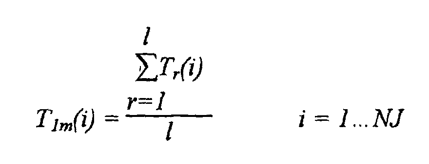
- block 43 goes on to a block 55, which calculates the average contiguous synchronous time series T 1m (i) defining the filtered signal calculated in block 22, according to the equation: i.e. the mean value of each sample T 1 (i) over the 1 revolutions considered is calculated.
- Convergence of the averaging process is then determined by calculating a convergence value ⁇ given by the sum, over all the samples, of the absolute value of the difference between the actual mean value of each sample and the mean value calculated in a previous revolution (at distance 4) divided by the sum of the mean samples in the previous revolution considered (at distance 4), according to the equation: where T 1m (i) represents the i -th sample of the 1 -th iteration, and T 1m-4 (i) represents the i -th sample of the 1-4-th iteration (block 56).
- the threshold comparison and alarm generating step in block 31 of Figure 3 is conveniently performed as described below with reference to Figure 5.
- RC2 is compared with first threshold TH1 (block 60); if RC2 ⁇ TH1 (YES output), block 60 goes back to block 21 in Figure 3 to continue monitoring with the next group of samples; conversely, if threshold TH1 has been exceeded (NO output of block 60), the event is memorized in event memory 153 (block 62) and RC2 is compared with second threshold TH2 (block 64).
- variable F (initialized in block 20 of Figure 3 to memorize whether threshold TH2 has already been exceeded) is set to (or confirmed at) the first predetermined value, 0 in the example shown (block 66), and block 66 goes back to block 21 of Figure 3 to continue monitoring with the next group of samples.
- the event is memorized in event memory 153 (block 68) and the value of variable F is determined (block 70).
- F is set to a second predetermined value, e.g. 1, (block 72), and block 72 goes back to block 21 of Figure 3 to continue monitoring with the next group of samples.
- variable F is at the second predetermined value, i.e. threshold TH2 has already been exceeded (NO output of block 70)
- a pilot alarm signal is generated (block 74)
- variable F is again set to the first predetermined value (block 76)
- block 76 goes back to block 21 of Figure 3 to continue monitoring with the next samples.
- the method provides for indicating conditions of unbalance resulting in severe vibration, which in turn severely stresses the shafts and may sooner or later result in failure of the monitored shaft.
- the method provides for distinguishing useful monitoring components from random noise and noise generated by other nearby moving members, and is therefore especially reliable for indicating problems arising and evolving rapidly in flight.
Landscapes
- Engineering & Computer Science (AREA)
- Physics & Mathematics (AREA)
- General Physics & Mathematics (AREA)
- General Engineering & Computer Science (AREA)
- Mechanical Engineering (AREA)
- Acoustics & Sound (AREA)
- Aviation & Aerospace Engineering (AREA)
- Testing Of Devices, Machine Parts, Or Other Structures Thereof (AREA)
- Measurement Of Mechanical Vibrations Or Ultrasonic Waves (AREA)
- Traffic Control Systems (AREA)
- Control Of Transmission Device (AREA)
Claims (11)
- Procédé de contrôle d'un ensemble de transmission d'un véhicule équipé de capteurs d'accélération, en particulier un hélicoptère, comportant les étapes consistant à :a) acquérir un signal à partir d'un capteur d'accélération;b) calculer une transformée dans le domaine de fréquence dudit signal afin d'obtenir une séquence d'échantillons;c) acquérir un échantillon dans ladite séquence d'échantillons;d) calculer une valeur d'amplitude réelle dudit échantillon acquis;e) calculer un écart relatif entre ladite valeur d'amplitude réelle et une valeur d'amplitude de référence; etf) comparer ledit écart relatif avec au moins un premier seuil prédéterminé (TH1, TH2).
- Procédé selon la revendication 1, selon lequel ladite transformée est une transformée de Fourier.
- Procédé selon la revendication 1 ou 2, selon lequel ladite étape d'acquisition d'un échantillon comporte l'acquisition d'un deuxième échantillon dans ladite séquence d'échantillons.
- Procédé selon la revendication 1 ou 2, selon lequel ladite étape de calcul d'un écart relatif comporte les calculs d'une quantité RC2 selon l'équation :
- Procédé selon la revendication 4, selon lequel lesdites étapes de a) à f) sont répétées pour un nombre d'itérations; et ladite valeur d'amplitude de référence est égale à la valeur d'amplitude réelle calculée dans une première itération.
- Procédé selon l'une quelconque des revendications précédentes, selon laquelle ladite étape de calcul d'une transformée est précédée par une étape d'échantillonnage et de filtrage dudit signal.
- Procédé selon la revendication 6, selon lequel ladite étape d'échantillonnage et de filtrage comprend les étapes consistant à :où T1(i) sont lesdits échantillons synchrones, et 1 est un compteur destiné à compter le nombre de tours dudit arbre.acquérir un nombre d'échantillons synchrones T1(i) pour chaque tour d'un arbre associé au dit capteur d'accélération; etcalculer une série temporelle moyenne T1m(i) selon l'équation :
- Procédé selon la revendication 7, selon lequel ladite étape de calcul d'une série temporelle moyenne est précédée par une étape de détermination de la présence de valeurs de signal significatives.
- Procédé selon la revendication 7 ou 8, selon lequel ladite étape de calcul d'une série temporelle moyenne est suivie par une étape de détermination de la convergence de ladite série temporelle moyenne.
- Procédé selon l'une quelconque des revendications précédentes, selon lequel ladite étape de comparaison dudit écart relatif comprend également l'étape de comparaison dudit écart relatif avec un deuxième seuil.
- Procédé selon la revendication 10, selon lequel ladite étape de comparaison dudit écart relatif comporte les étapes de mémorisation de l'information de dépassement de premier seuil lorsque ledit premier seuil est dépassé, et de génération d'un signal d'alarme lorsque ledit deuxième seuil est dépassé dans deux itérations successives.
Applications Claiming Priority (2)
| Application Number | Priority Date | Filing Date | Title |
|---|---|---|---|
| IT97TO000590A IT1293408B1 (it) | 1997-07-04 | 1997-07-04 | Metodo di sorveglianza di un gruppo di trasmissione in un veicolo dotato di sensori accelerometrici, in particolare in un elicottero. |
| ITTO970590 | 1997-07-04 |
Publications (3)
| Publication Number | Publication Date |
|---|---|
| EP0889314A2 EP0889314A2 (fr) | 1999-01-07 |
| EP0889314A3 EP0889314A3 (fr) | 1999-05-19 |
| EP0889314B1 true EP0889314B1 (fr) | 2003-02-19 |
Family
ID=11415833
Family Applications (1)
| Application Number | Title | Priority Date | Filing Date |
|---|---|---|---|
| EP98112404A Expired - Lifetime EP0889314B1 (fr) | 1997-07-04 | 1998-07-03 | Méthode de surveillance d'une transmission de véhicule équipée de capteurs d'accélération en particulier pour hélicoptère |
Country Status (5)
| Country | Link |
|---|---|
| US (1) | US6029930A (fr) |
| EP (1) | EP0889314B1 (fr) |
| JP (1) | JP4080602B2 (fr) |
| DE (1) | DE69811432T2 (fr) |
| IT (1) | IT1293408B1 (fr) |
Families Citing this family (15)
| Publication number | Priority date | Publication date | Assignee | Title |
|---|---|---|---|---|
| US6098921A (en) * | 1999-05-06 | 2000-08-08 | Piasecki Aircraft Corp. | Rotary wing aircraft supplementary power drive system |
| US6321602B1 (en) | 1999-09-28 | 2001-11-27 | Rockwell Science Center, Llc | Condition based monitoring by vibrational analysis |
| FR2803036B1 (fr) | 1999-12-23 | 2002-10-11 | Snecma | Detection de l'endommagement de pieces d'un moteur |
| DE10007236A1 (de) * | 2000-02-17 | 2001-08-23 | Zf Luftfahrttechnik Gmbh | Verfahren zum Überwachen und Auswerten von Zustandsparametern |
| US7434764B2 (en) * | 2005-12-02 | 2008-10-14 | Sikorsky Aircraft Corporation | Variable speed gearbox with an independently variable speed tail rotor system for a rotary wing aircraft |
| DE102008019578B4 (de) * | 2008-04-18 | 2010-11-11 | Wacker Neuson Se | Vorrichtung und Verfahren zum Erkennen von Schäden an einer Arbeitsmaschine |
| FR2957668B1 (fr) | 2010-03-19 | 2012-10-19 | Eurocopter France | Ensemble mecanique muni d'un moyen de surveillance d'anomalie structurale, boite de transmission munie d'un tel ensemble mecanique, et procede de surveillance d'anomalie structurale |
| FR2960639B1 (fr) * | 2010-05-28 | 2012-06-08 | Eurocopter France | Procede de surveillance d'anomalie structurale d'un ensemble mecanique |
| EP2549257B1 (fr) | 2011-07-18 | 2013-10-30 | Siemens Aktiengesellschaft | Procédé de détection de dommages sur des engrenages |
| CN103869053B (zh) * | 2014-03-24 | 2015-07-15 | 焦振志 | 区域地球化学调查样品分析异常点抽检方法 |
| US9580187B2 (en) * | 2014-04-22 | 2017-02-28 | Sikorsky Aircraft Corporation | Rotor index sensor system |
| DE102017206760A1 (de) * | 2017-04-21 | 2018-10-25 | Rolls-Royce Deutschland Ltd & Co Kg | Verfahren und Vorrichtung zur Bestimmung von Beschädigung, Verschleiß und/oder Unwucht in einem Getriebe, insbesondere einem Umlaufrädergetriebe |
| CN108875710B (zh) * | 2018-07-24 | 2021-10-08 | 杭州电子科技大学 | 基于能量阈值算法的电梯门运行速度估计方法 |
| CN110657885B (zh) * | 2019-10-14 | 2022-03-11 | 深圳市蓝度汽车电控技术有限公司 | 一种震动传感器的震动报警方法、系统及终端 |
| US12012219B2 (en) * | 2020-07-17 | 2024-06-18 | The Boeing Company | Aircraft buffet detection |
Family Cites Families (5)
| Publication number | Priority date | Publication date | Assignee | Title |
|---|---|---|---|---|
| US3699806A (en) * | 1967-07-14 | 1972-10-24 | Bjorn Weichbrodt | Early detection of damage to machine elements in rolling engagement |
| US5210704A (en) * | 1990-10-02 | 1993-05-11 | Technology International Incorporated | System for prognosis and diagnostics of failure and wearout monitoring and for prediction of life expectancy of helicopter gearboxes and other rotating equipment |
| US5501105A (en) * | 1991-10-02 | 1996-03-26 | Monitoring Technology Corp. | Digital signal processing of encoder signals to detect resonances in rotating machines |
| US5365787A (en) * | 1991-10-02 | 1994-11-22 | Monitoring Technology Corp. | Noninvasive method and apparatus for determining resonance information for rotating machinery components and for anticipating component failure from changes therein |
| JP3029981B2 (ja) * | 1995-04-27 | 2000-04-10 | 株式会社コミュータヘリコプタ先進技術研究所 | ヘリコプタの動力伝達装置 |
-
1997
- 1997-07-04 IT IT97TO000590A patent/IT1293408B1/it active IP Right Grant
-
1998
- 1998-07-03 EP EP98112404A patent/EP0889314B1/fr not_active Expired - Lifetime
- 1998-07-03 DE DE69811432T patent/DE69811432T2/de not_active Expired - Lifetime
- 1998-07-06 JP JP19023998A patent/JP4080602B2/ja not_active Expired - Fee Related
- 1998-07-06 US US09/110,621 patent/US6029930A/en not_active Expired - Lifetime
Also Published As
| Publication number | Publication date |
|---|---|
| JPH11124097A (ja) | 1999-05-11 |
| DE69811432T2 (de) | 2003-08-14 |
| US6029930A (en) | 2000-02-29 |
| ITTO970590A1 (it) | 1999-01-04 |
| DE69811432D1 (de) | 2003-03-27 |
| IT1293408B1 (it) | 1999-03-01 |
| JP4080602B2 (ja) | 2008-04-23 |
| EP0889314A2 (fr) | 1999-01-07 |
| EP0889314A3 (fr) | 1999-05-19 |
Similar Documents
| Publication | Publication Date | Title |
|---|---|---|
| EP0889314B1 (fr) | Méthode de surveillance d'une transmission de véhicule équipée de capteurs d'accélération en particulier pour hélicoptère | |
| EP0889316B1 (fr) | Méthode de surveillance d'une transmission de véhicule équipée de capteurs d'accélération en particulier pour hélicoptère | |
| US7430483B2 (en) | Method and apparatus for diagnosing a mechanism | |
| EP0889315B1 (fr) | Méthode de surveillance d'une transmission de véhicule équipée de capteurs d'accélération en particulier pour hélicoptère | |
| EP0899553B1 (fr) | Procédé de surveillance d'un engrenage épicycloidal muni d'accéléromètres dans un véhicule, en particulier dans un hélicoptère | |
| Blunt et al. | Detection of a fatigue crack in a UH-60A planet gear carrier using vibration analysis | |
| EP0889313B1 (fr) | Méthode de surveillance d'une transmission de véhicule équipée de capteurs d'accélération en particulier pour hélicoptère | |
| Mechefske et al. | Fault detection and diagnosis in low speed rolling element bearings Part I: The use of parametric spectra | |
| Djebala et al. | Rolling bearing fault detection using a hybrid method based on empirical mode decomposition and optimized wavelet multi-resolution analysis | |
| Zhou et al. | Using frequency domain analysis techniques for diagnosis of planetary bearing defect in a CH-46E helicopter aft gearbox | |
| US6298725B1 (en) | Method for the separation of epicyclic planet gear vibration signatures | |
| Wu et al. | Vibration monitoring for fault diagnosis of helicopter planetry gears | |
| CN107436244B (zh) | 基于频率分段振动数据采集的设备故障报警方法 | |
| Wang et al. | A model-based gear diagnostic technique | |
| EP1300668A1 (fr) | Procédé pour la séparation des signeaux des vibrations dans un engrenage planétaire | |
| Chenxi et al. | Intelligent identification of bearing faults using time domain features | |
| Bechhoefer | Condition monitoring of a cycloid gearbox | |
| Tuma et al. | Assessment of gear quality considering the time domain analysis of noise and vibration signals | |
| Pawlik | Vibroacoustic method of diagnosing rotating machines operating under variable load | |
| Ma et al. | A new approach to gear vibration demodulation and its application to defect detection | |
| Tsutsui et al. | Relationship Between Rotational Angle and Time-Synchronous-Averaged Meshing | |
| Had et al. | A New Time Frequency Based Indicator for Planet Gears Anisotropy in Planetary Gearbox | |
| CN118067391A (zh) | 一种行星轮故障诊断的扭振信号分离方法 | |
| 김건 | Quantitative performance evaluation of a knock sensor for vibration-based fault diagnosis in a planetary gearbox | |
| Abidat et al. | COMPARY STUDY OF EFFECTIVE AND SENSITIVE VIBRATION PROCESSING TECHNIQUES FOR LOCAL FAULT DETECTION IN THE GEARS IN A GEARBOX |
Legal Events
| Date | Code | Title | Description |
|---|---|---|---|
| PUAI | Public reference made under article 153(3) epc to a published international application that has entered the european phase |
Free format text: ORIGINAL CODE: 0009012 |
|
| AK | Designated contracting states |
Kind code of ref document: A2 Designated state(s): DE FR GB |
|
| AX | Request for extension of the european patent |
Free format text: AL;LT;LV;MK;RO;SI |
|
| PUAL | Search report despatched |
Free format text: ORIGINAL CODE: 0009013 |
|
| AK | Designated contracting states |
Kind code of ref document: A3 Designated state(s): AT BE CH CY DE DK ES FI FR GB GR IE IT LI LU MC NL PT SE |
|
| AX | Request for extension of the european patent |
Free format text: AL;LT;LV;MK;RO;SI |
|
| 17P | Request for examination filed |
Effective date: 19991022 |
|
| AKX | Designation fees paid |
Free format text: DE FR GB |
|
| RAP1 | Party data changed (applicant data changed or rights of an application transferred) |
Owner name: AGUSTA S.P.A. |
|
| GRAG | Despatch of communication of intention to grant |
Free format text: ORIGINAL CODE: EPIDOS AGRA |
|
| 17Q | First examination report despatched |
Effective date: 20020529 |
|
| GRAG | Despatch of communication of intention to grant |
Free format text: ORIGINAL CODE: EPIDOS AGRA |
|
| GRAH | Despatch of communication of intention to grant a patent |
Free format text: ORIGINAL CODE: EPIDOS IGRA |
|
| GRAH | Despatch of communication of intention to grant a patent |
Free format text: ORIGINAL CODE: EPIDOS IGRA |
|
| GRAA | (expected) grant |
Free format text: ORIGINAL CODE: 0009210 |
|
| AK | Designated contracting states |
Designated state(s): DE FR GB |
|
| REG | Reference to a national code |
Ref country code: GB Ref legal event code: FG4D |
|
| REF | Corresponds to: |
Ref document number: 69811432 Country of ref document: DE Date of ref document: 20030327 Kind code of ref document: P |
|
| ET | Fr: translation filed | ||
| PLBE | No opposition filed within time limit |
Free format text: ORIGINAL CODE: 0009261 |
|
| STAA | Information on the status of an ep patent application or granted ep patent |
Free format text: STATUS: NO OPPOSITION FILED WITHIN TIME LIMIT |
|
| 26N | No opposition filed |
Effective date: 20031120 |
|
| REG | Reference to a national code |
Ref country code: FR Ref legal event code: PLFP Year of fee payment: 18 |
|
| PGFP | Annual fee paid to national office [announced via postgrant information from national office to epo] |
Ref country code: GB Payment date: 20150708 Year of fee payment: 18 Ref country code: DE Payment date: 20150707 Year of fee payment: 18 |
|
| PGFP | Annual fee paid to national office [announced via postgrant information from national office to epo] |
Ref country code: FR Payment date: 20150709 Year of fee payment: 18 |
|
| REG | Reference to a national code |
Ref country code: DE Ref legal event code: R082 Ref document number: 69811432 Country of ref document: DE Representative=s name: ZENZ PATENTANWAELTE PARTNERSCHAFT MBB, DE |
|
| REG | Reference to a national code |
Ref country code: DE Ref legal event code: R119 Ref document number: 69811432 Country of ref document: DE |
|
| GBPC | Gb: european patent ceased through non-payment of renewal fee |
Effective date: 20160703 |
|
| PG25 | Lapsed in a contracting state [announced via postgrant information from national office to epo] |
Ref country code: DE Free format text: LAPSE BECAUSE OF NON-PAYMENT OF DUE FEES Effective date: 20170201 Ref country code: FR Free format text: LAPSE BECAUSE OF NON-PAYMENT OF DUE FEES Effective date: 20160801 |
|
| REG | Reference to a national code |
Ref country code: FR Ref legal event code: ST Effective date: 20170331 |
|
| PG25 | Lapsed in a contracting state [announced via postgrant information from national office to epo] |
Ref country code: GB Free format text: LAPSE BECAUSE OF NON-PAYMENT OF DUE FEES Effective date: 20160703 |