EP0889459A2 - Struktur mit niedrigem Schallinduzierte-Schwingungsreaktion - Google Patents
Struktur mit niedrigem Schallinduzierte-Schwingungsreaktion Download PDFInfo
- Publication number
- EP0889459A2 EP0889459A2 EP98111732A EP98111732A EP0889459A2 EP 0889459 A2 EP0889459 A2 EP 0889459A2 EP 98111732 A EP98111732 A EP 98111732A EP 98111732 A EP98111732 A EP 98111732A EP 0889459 A2 EP0889459 A2 EP 0889459A2
- Authority
- EP
- European Patent Office
- Prior art keywords
- facesheet
- holes
- core
- panel
- faces
- Prior art date
- Legal status (The legal status is an assumption and is not a legal conclusion. Google has not performed a legal analysis and makes no representation as to the accuracy of the status listed.)
- Granted
Links
Images




Classifications
-
- G—PHYSICS
- G10—MUSICAL INSTRUMENTS; ACOUSTICS
- G10K—SOUND-PRODUCING DEVICES; METHODS OR DEVICES FOR PROTECTING AGAINST, OR FOR DAMPING, NOISE OR OTHER ACOUSTIC WAVES IN GENERAL; ACOUSTICS NOT OTHERWISE PROVIDED FOR
- G10K11/00—Methods or devices for transmitting, conducting or directing sound in general; Methods or devices for protecting against, or for damping, noise or other acoustic waves in general
- G10K11/16—Methods or devices for protecting against, or for damping, noise or other acoustic waves in general
- G10K11/172—Methods or devices for protecting against, or for damping, noise or other acoustic waves in general using resonance effects
-
- B—PERFORMING OPERATIONS; TRANSPORTING
- B64—AIRCRAFT; AVIATION; COSMONAUTICS
- B64G—COSMONAUTICS; VEHICLES OR EQUIPMENT THEREFOR
- B64G1/00—Cosmonautic vehicles
- B64G1/22—Parts of, or equipment specially adapted for fitting in or to, cosmonautic vehicles
Definitions
- the invention is directed to the field of vibroacoustics and, more particularly, to a structure for use in high-energy acoustic environments having low acoustically-induced vibration characteristics.
- Spacecrafts such as satellites are placed in orbit using a dedicated launch vehicle.
- Spacecraft vibroacoustic environments and associated loads result from the launch vehicle rocket engines supersonic flow and the shearing of adjacent air.
- the acoustic energy significant to structural components is normally mostly within the frequency range of about 30-500 Hz.
- the apparent sound and reflections of this sound generally reach a peak level just at lift-off and then decay gradually as the launch vehicle increases speed and gains altitude.
- the initial engine noise is reverberated throughout the launch facility and is ultimately transmitted through the launch vehicle fairing where it impinges onto the spacecraft.
- launch vehicles include a shroud which surrounds the spacecraft, protects against obvious wind loads, and absorbs some acoustic energy.
- Shrouds do not, however, provide sufficient acoustic protection of the payload. Measures are used to supplement the shroud and increase the acoustic protection of the spacecraft, including adding sound absorptive materials to the shroud. Although these materials add some acoustic protection, they also add undesirable weight to the launch vehicle and reduce lift capability.
- the payload is mounted to the spacecraft bus.
- Honeycomb panels including imperforate graphite or aluminum facesheets on a honeycomb sheet core are commonly placed on or comprise the bus. Acoustic energy that impinges on the panels is reflected, absorbed or transmitted through the panels. The absorbed energy results in panel vibrational excitation.
- the transmission loss through a panel is related to the sound energy loss between an inlet face and an outlet face due to reflection or absorption.
- Known honeycomb panels exhibit this transmission loss and can be designed to maximize sound absorption so as to reduce noise.
- Vibroacoustics are important for honeycomb panels that have appreciable surface area and are lightly loaded. Such panels are susceptible to acoustic excitation during liftoff, due to their high stiffness, low weight, low damping and high acoustic coupling factors.
- panels with composite facesheets respond at higher levels than panels with facesheets of aluminum. The response of a panel is highly affected by its distributed mass loading. Lightly loaded panels have a much higher response than panels with loads equal to multiples of mass per square foot.
- Composite panels also exhibit less damping than aluminum panels due to bonded joints versus bolted joints, for example, which relates to their higher response. Because of weight constraints, spacecraft now utilize increasing numbers of composite parts in place of heavier metallic parts, oftentimes reducing the bus structural weight by as much as 20-30%.
- Known vibroacoustic reduction methods involve adding mass to the panels in the form of more structure, or using energy absorbing or dissipating devices. Adding mass or absorbing/dissipating devices achieves vibroacoustic reduction, but it also significantly increases the cost of launching the spacecraft associated with the added mass, and therefore is less than totally satisfactory.
- a panel structure for use in high-energy acoustic environments such as in spacecrafts that (I) allows reduced acoustic energy absorption and reduced acoustically induced structural vibration excitation of the structure and components to which the structure is attached; and (ii) is lightweight.
- the present invention provides an improved structure that satisfies the above-described needs.
- the present invention provides a low vibroacoustic structure for use in high-energy acoustic environments.
- the structure is typically in the form of a multilayer panel comprising a first facesheet including a first inlet face, a first outlet face, and a plurality of first holes extending through the first facesheet between the first inlet face and the first outlet face.
- a second facesheet includes a second inlet face, a second outlet face, and a plurality of second holes extending through the second facesheet between the second inlet face and the second outlet face.
- a core having an inlet surface and an outlet surface is disposed between the first and second facesheets.
- the first facesheet faces the inlet surface of the core and the second facesheet faces the outlet surface.
- the core defines a plurality of passages extending between the inlet and outlet surfaces.
- the core is typically a honeycomb sheet, including a plurality of cells directed substantially perpendicular to the first and second facesheets.
- the holes of the first and second facesheets are preferably in substantially aligned communication with the passages of the core to form continuous channels through the panel.
- the channels reduce acoustically induced vibration of the panel.
- the first and second facesheets can be comprised of a lightweight metal, a metal matrix composite or a polymer matrix composite.
- the honeycomb sheet is typically comprised of a lightweight metal.
- the low vibroacoustic structure according to the present invention (I) has reduced acoustically-induced vibration characteristics over the frequency range of from about 20 Hz to about 500 Hz; and (ii) is lightweight, making it ideally suitable for use in applications having strict weight constraints.
- the panel construction is particularly suitable for spacecraft applications.
- the panel can be used in a spacecraft structure such as a spacecraft bus to provide acoustic protection and reduce acoustically-induced vibration of the spacecraft bus, and any payload attached to the bus, during launch of the spacecraft.
- a typical use of the panel in the spacecraft bus is an equipment compartment panel.
- the low vibroacoustic structure can also be used in other spacecraft applications in which vibration is a concern such as antenna reflectors.
- a low vibroacoustic structure according to the present invention is illustrated in Figs. 1-3.
- the illustrated low vibroacoustic structure is in the form of a panel 10 comprising a first facesheet 12 , a core 14 and a second facesheet 16 .
- the structure can be provided in other forms as described below.
- the first facesheet 12 comprises an inlet face 18 and an outlet face 20 .
- the faces 18 , 20 are typically flat.
- a plurality of first holes 22 are formed through the first facesheet 12 between the inlet face 18 and the outlet face 20 .
- the facesheet has a height, H, a width, W, and a thickness, T. The dimensions of the panel can be varied depending on the application of the panel.
- the first holes 22 are typically circular shaped.
- the holes 22 can alternately have other non-circular shapes.
- the holes 22 typically have a diameter of from about 0.001 in. to about 0.125 in., and an on-center hole spacing, S, of from about 0.007 in. to about 0.5 in.
- the holes 22 can be arranged in a staggered pattern as shown, or alternately in other patterns such as aligned rows and columns (not shown).
- the holes 22 can have a total cross-sectional area of from about 8% to about 51% of the area of the inlet face 18 of the first facesheet 12 . Increasing this percentage reduces the weight of the panel 10 , but reduces the panel bending strength.
- the hole size reduces the panel bending strength as larger holes act as stress raisers in the panel.
- the size, spacing and area percentage of the holes 22 can be varied depending on performance considerations including acoustic response as described below, and panel stiffness and bending strength.
- the first facesheet 12 typically has a thickness of from about 0.025 in. to about 0.125 in.
- the panel 10 can be used in a spacecraft bus as an equipment compartment panel.
- the mass loading on the panels 10 from electronic equipment is typically about 3-4 lb/ft 2 .
- the core 14 has opposed surfaces to which the first and second facesheets 12 , 16 are attached. As illustrated in Fig. 3, the core 14 is typically a honeycomb sheet having an inlet face 24 in abutting contact with the outlet face 20 of the first facesheet 12 , and an outlet face 26 in abutting contact with a second inlet face 28 of the second facesheet 16 .
- the honeycomb sheet form of the core 14 includes a plurality of cells 30 defining passages 32 directed substantially perpendicular to the first facesheet 12 and the second facesheet 16 .
- the cells 30 are typically hexagonal shaped and typically have a diameter of about 0.125 in.
- the cells 30 can alternately have other polygonal shapes or be circular.
- the thickness of the core 14 is typically from about 0.625 in. to about 1.25 in.
- the cell 30 diameter and the core 14 thickness can be varied depending on strength and stiffness requirements of the panel 10 .
- the second facesheet 16 comprises the second inlet face 28 , a second outlet face 34 , and a plurality of second holes 36 extending through the second facesheet 16 between the second inlet face 28 and the second outlet face 34 .
- the first holes 22 , the passages 32 and the second holes 36 define channels 38 through the panel 10 .
- the first facesheet 12 and the second facesheet 16 can be comprised of a suitable lightweight metal, metal matrix Composite, or polymer matrix composite material.
- Suitable metals include aluminum, titanium and magnesium.
- Suitable metal matrix composite materials can include aluminum, titanium and magnesium matrices, and silicon fibers, titanium carbide and titanium boride fibers.
- Suitable polymer matrix composite materials include fiber reinforced plastic composite materials which comprise thermosetting or thermoplastic matrices, and various compositions of embedded fibers.
- the matrix can comprise epoxy-based and polycyanate-based resin systems.
- Epoxy graphite composite comprised of an epoxy resin matrix and graphite fibers is extremely lightweight, and provides high lateral stiffness. Epoxy graphite composite also has a low coefficient of thermal expansion for high thermal dimensional stability, making it advantageous for mounting to high-precision instruments.
- a suitable epoxy graphite perforated composite material is commercially available from Aztex of Waltham, Massachusetts.
- Continuous fiber polymer matrix composites provide superior strength and stiffness to weight ratios as compared to aluminum facesheets.
- composite sheets having a small hole diameter such as about 0.025 in.
- composite fibers can be loosely woven around the holes without causing fiber breakage and reduced sheet strength.
- Fiber materials having properties similar to graphite fibers such as "KEVLAR" and glass fibers can optionally be used in the facesheets 12 , 16 .
- the core 14 is typically formed of aluminum.
- the density of aluminum honeycomb sheet is about 3.1-3.3 lb/ft 3 .
- suitable lightweight metallic and non-metallic materials such as formed plastics can be used to construct the core 14 .
- the first facesheet 12 and the second facesheet 16 can be attached to the core 14 using a suitable adhesive.
- the adhesive can be FM 964 adhesive available from 3M Corporation of St. Paul, Minnesota.
- the first and second facesheets 12 , 16 can each have a layered structure comprised of multiple thin layers, and with the holes in the different layers being in alignment with each other (not shown).
- the panel 10 provides important advantages in regard to reducing acoustically-induced vibration.
- the flat, perforated structure of the panel 10 does not efficiently couple to external sound pressure as compared to conventional, non-perforated acoustic panels, regardless of sound phase and sound direction.
- Reduced structural acoustic coupling results in less vibrational energy being created by the panel 10 .
- Opposite phase pressure differentials on each side of the panel are significantly reduced because the holes formed in the first and second facesheets 12 , 16 and the core 14 form through channels, allowing pressure to readily travel through the panel. Reduced pressure differentials result in the panel being driven less by the sound.
- Panels according to the present invention with perforated facesheets on opposed sides of a honeycomb core were fabricated and tested for responsiveness to white noise acoustic excitation.
- the panel facesheets were fabricated from sheet aluminum, 0.025 in. thick, and holes of various sizes and spacings were formed through the thickness of the sheets. Both facesheets for each panel had identical hole sizes and hole spacings. Referring to Fig. 2, overall panel dimensions were 35 in. height, 43 in. width and 0.75 in. thickness.
- the honeycomb core was comprised of aluminum, with a 0.125 in. cell diameter, 0.0007 in. wall thickness, and an equivalent core density of 3.1 lb./ft 3 .
- Panel 1 comprised solid facesheets with no holes.
- Panels 2-4 had a hole spacing of 0.25 in., and different hole diameters, numbers of holes/in. 2 , and percentages of hole total area to facial area of the facesheets.
- Panels 5 and 6 had a hole spacing of 0.5 in., and the different hole characteristics listed.
- the panels 10 were suspended individually in a four foot on each side acoustic anechoic chamber 40 , approximately one foot from a window 42 , which lead to a noise source reverberant chamber 44 .
- the panels were freely suspended in this manner to avoid boundary conditions associated with fixed attachment of the panels to the test structure.
- a 400 watt speaker 46 provided the acoustic excitation of the panel.
- An input microphone (not shown) was located approximately 6 in. from the panel, to measure the panel near field sound pressure levels.
- An accelerometer 48 was positioned in a lower corner of the panels 10 to record the panel response to the acoustic excitation. Any corner of the panels allowed nearly all the vibration modes below 500 Hz to be observed.
- SPL white noise sound pressure levels
- PSD Random vibration power spectral density
- Root-mean-square (Grms) acceleration levels were calculated from the PSD responses of the panels.
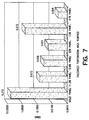
- the Grms acceleration levels at 66 dB SPL, 86 dB SPL and 91 dB SPL, respectively, are shown graphically in Figs. 6-8, and are given in TABLE 2 below.
- the Grms level is related to the area under the PSD response curve such as shown in Fig. 5 and represents the total amount of energy absorbed by the panel during testing.
- Hole diameter alone did not have an apparent strong influence on the panel response. Hole diameter was only significant when holes with large spacing did not align through the core from one side of the panel to the other (i.e., the misalignment between the holes of the facesheets and the passages of the core resulted in non-continuous channels through the thickness of the entire panel).
- the hole spacing also influenced the level of reflected sound from each panel. This was evidenced by slightly higher average SPL microphone readings for panels having large hole spacings (panels 5 and 6) or no holes (panel 1) and conversely, lower microphone measurements of reflected sound from panels with higher hole density (panels 2-4).
- the speaker was driven with identical input power levels for each panel.
- test results indicate that it is important that the channels extending between the opposed faces of the panel are continuous to enable acoustic energy to travel through the panel. This is especially important for small cell diameter core with respect to the hole size and spacing of the facesheets. Misalignment of the holes in the facesheets and the passages in the core reduces pressure transmission through the panel and causes the panel to approach the sound absorption behavior of a panel having non-perforated facesheets. Alignment of the two facesheets is less significant for facesheets having holes that are much smaller in diameter and spacing than the core cell diameter.
- the panel 10 according to the present invention can be used, for example, in a spacecraft bus 50 .
- the bus 50 comprises a frame 52 to which the panels 10 are attached.
- the panels 10 can be equipment compartment panels.
- the panels 10 can form the frame of the spacecraft bus 50 .
- the payload is typically mounted to the interior face (not shown) of the panels.
- sound pressure is transmitted through the panels 10 , thus reducing acoustically induced vibration of the electronic equipment and also the spacecraft bus.
- the possibility of damage to sensitive payload components such as the electronic equipment caused by vibration is significantly reduced as compared to known panels having non-perforated facesheets.
- the panels 10 can be mounted to a supporting structure using various mounting bracket configurations.
- the opposed facesheets 12 , 16 of the panel 10 can be adhered to the bracket 54 .
- the panel 10 can alternately be fastened around the perimeter to the bracket 56 using small fasteners and inserts 58 which extend through the panel.
- Electronic components can be attached to the panels 10 using fasteners sized to extend through the panels with small inserts bonded in the panels (not shown).
- the present panel 10 provides such a major reduction in the vibroacoustic environment at about 20-500 Hz frequencies that it may not be necessary to specify or even test attached sensitive electronic equipment. Although spacecraft electronic assemblies are typically exposed to vibration testing to screen manufacturing flaws, rigorous high level testing to establish survivability may not be needed. Thus, the present invention can decrease costly testing expenses.
- the panel 10 can be used in various other structures that are adversely affected by acoustic excitation.
- the panel structure is particularly advantageous for use in structures that have appreciable surface area and are lightly loaded, such as antenna reflectors, and can benefit significantly from reduced structural response to acoustic excitation.
Landscapes
- Engineering & Computer Science (AREA)
- Physics & Mathematics (AREA)
- Acoustics & Sound (AREA)
- Multimedia (AREA)
- Remote Sensing (AREA)
- Aviation & Aerospace Engineering (AREA)
- Soundproofing, Sound Blocking, And Sound Damping (AREA)
- Laminated Bodies (AREA)
- Building Environments (AREA)
Applications Claiming Priority (2)
| Application Number | Priority Date | Filing Date | Title |
|---|---|---|---|
| US887500 | 1997-07-02 | ||
| US08/887,500 US5912442A (en) | 1997-07-02 | 1997-07-02 | Structure having low acoustically-induced vibration response |
Publications (3)
| Publication Number | Publication Date |
|---|---|
| EP0889459A2 true EP0889459A2 (de) | 1999-01-07 |
| EP0889459A3 EP0889459A3 (de) | 2000-02-23 |
| EP0889459B1 EP0889459B1 (de) | 2003-09-10 |
Family
ID=25391283
Family Applications (1)
| Application Number | Title | Priority Date | Filing Date |
|---|---|---|---|
| EP98111732A Expired - Lifetime EP0889459B1 (de) | 1997-07-02 | 1998-06-25 | Struktur mit niedrigem Schallinduzierte-Schwingungsreaktion |
Country Status (4)
| Country | Link |
|---|---|
| US (1) | US5912442A (de) |
| EP (1) | EP0889459B1 (de) |
| JP (1) | JPH1191017A (de) |
| DE (1) | DE69817927T2 (de) |
Cited By (7)
| Publication number | Priority date | Publication date | Assignee | Title |
|---|---|---|---|---|
| EP1336727A3 (de) * | 2002-02-18 | 2003-10-29 | Nissan Motor Company, Limited | Schalldämpfer |
| FR2868502A1 (fr) * | 2004-03-30 | 2005-10-07 | Rhodia Chimie Sa | Carter insonorise permettant l absorption des ondes a coustiques. |
| CN103038484A (zh) * | 2010-05-19 | 2013-04-10 | 斯奈克玛 | 多层声处理板 |
| CN102089801B (zh) * | 2008-05-22 | 2013-05-29 | 3M创新有限公司 | 包括网片层的多层吸声结构 |
| EP1873751B1 (de) | 2006-06-29 | 2017-09-27 | United Technologies Corporation | Viskothermaler Liner ohne Echo |
| EP3438967A4 (de) * | 2016-03-29 | 2019-04-24 | FUJIFILM Corporation | Schallisolierungsstruktur, öffnungsstruktur, zylindrische struktur, fensterelement und trennwand |
| WO2023089267A1 (fr) * | 2021-11-19 | 2023-05-25 | Safran | Procede de fabrication d'un composant multicellulaire |
Families Citing this family (78)
| Publication number | Priority date | Publication date | Assignee | Title |
|---|---|---|---|---|
| US6224020B1 (en) * | 1998-12-24 | 2001-05-01 | Alliant Techsystems, Inc. | Payload fairing with improved acoustic suppression |
| GB0016149D0 (en) * | 2000-06-30 | 2000-08-23 | Short Brothers Plc | A noise attenuation panel |
| GB2364535A (en) * | 2000-07-10 | 2002-01-30 | Chiao Hsiang Wang | Sound absorbing panel |
| US7279214B2 (en) | 2000-09-09 | 2007-10-09 | EEEA Entwicklungsgesellschaft fur Akustik mbH | Floor covering having a strong noise-reducing properties |
| US6509081B1 (en) * | 2000-09-28 | 2003-01-21 | The Boeing Company | No-septum acoustic sandwich panel, and apparatus and method for suppressing noise in a nozzle |
| FR2815603B1 (fr) * | 2000-10-20 | 2003-02-21 | Eurocopter France | Panneau insonorisant, en particulier panneau structural ou d'habillage d'un aeronef a voilure tournante |
| US7343715B2 (en) * | 2001-05-17 | 2008-03-18 | Toray Industries, Inc. | Sound-proof wall made of FRP, and method of producing the same |
| US7658046B2 (en) * | 2001-09-11 | 2010-02-09 | Usg Interiors, Inc. | Moiré ceiling panels |
| JP4034252B2 (ja) * | 2003-09-29 | 2008-01-16 | 株式会社林技術研究所 | 自動車用サンバイザー |
| US7320455B2 (en) * | 2003-10-24 | 2008-01-22 | Newport Corporation | Instrumented platform for vibration-sensitive equipment |
| JP2005247208A (ja) * | 2004-03-05 | 2005-09-15 | Hayashi Engineering Inc | 自動車用サンバイザー |
| US7055704B2 (en) * | 2004-04-09 | 2006-06-06 | Composite Concepts, Llc | Lightweight, structurally integral, and strong composite rack shelving |
| JP2006002869A (ja) * | 2004-06-18 | 2006-01-05 | Toho Tenax Co Ltd | サンドイッチパネル |
| US8276873B2 (en) * | 2004-10-22 | 2012-10-02 | Newport Corporation | Instrumented platform for vibration-sensitive equipment |
| US8231098B2 (en) | 2004-12-07 | 2012-07-31 | Newport Corporation | Methods and devices for active vibration damping of an optical structure |
| CN100398213C (zh) * | 2005-12-27 | 2008-07-02 | 中国科学院上海光学精密机械研究所 | 易清洁的精密光学平台 |
| US20070154682A1 (en) * | 2005-12-29 | 2007-07-05 | Lear Corporation | Molded sound absorber with increased surface area |
| JP2007256750A (ja) * | 2006-03-24 | 2007-10-04 | Yamaha Corp | 吸音材及び吸音材の製造方法並びに吸音パネル |
| US7540354B2 (en) * | 2006-05-26 | 2009-06-02 | United Technologies Corporation | Micro-perforated acoustic liner |
| US7935205B2 (en) * | 2006-06-19 | 2011-05-03 | United Technologies Corporation | Repair of composite sandwich structures |
| US8141723B2 (en) * | 2006-08-18 | 2012-03-27 | Plano Molding Company | Inverted cell honeycomb structure shelving |
| US7955698B2 (en) * | 2006-11-15 | 2011-06-07 | Honeywell International Inc. | Fiber-based acoustic treatment material and methods of making the same |
| FR2912186B1 (fr) * | 2007-02-01 | 2013-07-05 | Airbus France | Dispositif de traitement acoustique des bruits de turbine et de combustion |
| FR2915522A1 (fr) * | 2007-04-30 | 2008-10-31 | Airbus France Sas | Panneau acoustique a caracteristique acoustique variable |
| US7947364B2 (en) * | 2007-08-16 | 2011-05-24 | New Mexico Technical Research Foundation | Energy-attenuation structure |
| US20090188748A1 (en) * | 2008-01-24 | 2009-07-30 | Honeywell International Inc. | Noise suppression panels and repair methods therefor |
| JP2011519433A (ja) * | 2008-04-22 | 2011-07-07 | スリーエム イノベイティブ プロパティズ カンパニー | 複合吸音シート |
| US7705522B2 (en) * | 2008-06-06 | 2010-04-27 | Toyota Motor Engineering & Manufacturing North America, Inc. | Adjustable sound panel with electroactive actuators |
| US8127889B1 (en) * | 2009-09-15 | 2012-03-06 | The Boeing Company | Noise reduction system for structures |
| DE102010026834A1 (de) * | 2010-07-12 | 2012-01-12 | Rolls-Royce Deutschland Ltd & Co Kg | Gasturbinenabgaskonus |
| EP2659159B1 (de) | 2010-12-29 | 2019-05-08 | Newport Corporation | Abstimmbare schwingungsdämpfer und verfahren zu ihrer herstellung und abstimmung |
| KR101964644B1 (ko) * | 2012-05-10 | 2019-04-02 | 엘지전자 주식회사 | 소음저감부가 구비된 가전기기 |
| JP2014019121A (ja) * | 2012-07-23 | 2014-02-03 | Mimaki Engineering Co Ltd | 媒体支持装置および媒体加工装置 |
| US8657067B1 (en) * | 2012-09-25 | 2014-02-25 | The Boeing Company | Acoustic damping device for noise reduction |
| FR3001409B1 (fr) | 2013-01-29 | 2015-07-03 | Herakles | Procede de fabrication d'une structure alveolaire de forme courbee en materiau composite |
| FR3001452B1 (fr) * | 2013-01-29 | 2015-02-13 | Herakles | Procede de fabrication d'un panneau d'attenuation acoustique de forme courbee |
| US9235937B1 (en) | 2013-06-05 | 2016-01-12 | Analog Devices, Inc. | Mounting method for satellite crash sensors |
| US9370827B2 (en) * | 2013-08-28 | 2016-06-21 | The Boeing Company | System and method for forming perforations in a barrel section |
| GB2546449B (en) * | 2014-12-15 | 2018-08-01 | Jaguar Land Rover Ltd | Acoustic baffle |
| US20160215700A1 (en) * | 2015-01-23 | 2016-07-28 | Rohr, Inc. | Inner fixed structure acoustic panel with directional perforations |
| US9640164B2 (en) * | 2015-02-27 | 2017-05-02 | The Boeing Company | Sound attenuation using a cellular core |
| USD784564S1 (en) * | 2015-07-17 | 2017-04-18 | Arktura Llc | Architectural panel |
| USD794222S1 (en) * | 2015-07-17 | 2017-08-08 | Arktura Llc | Architectural panel |
| USD784563S1 (en) * | 2015-07-17 | 2017-04-18 | Arktura Llc | Architectural panel |
| US9752595B2 (en) * | 2015-11-03 | 2017-09-05 | Rohr, Inc. | Nacelle core with insert |
| JP6669528B2 (ja) * | 2016-02-25 | 2020-03-18 | 岐阜プラスチック工業株式会社 | 遮音パネル |
| JP6955283B2 (ja) * | 2016-02-25 | 2021-10-27 | 岐阜プラスチック工業株式会社 | 遮音パネル |
| JP6625227B2 (ja) | 2016-08-31 | 2019-12-25 | 富士フイルム株式会社 | 防音構造、及び防音システム |
| FR3075972B1 (fr) * | 2017-12-26 | 2020-12-04 | Aer | Systeme de transmission et/ou de reception d'onde acoustique optimisant le transfert d'energie acoustique entre un emetteur et/ou un recepteur acoustique |
| US10675768B2 (en) | 2018-03-27 | 2020-06-09 | The Boeing Company | Robotic end effector assembly, system, and method of using the same |
| US11325718B2 (en) * | 2018-05-02 | 2022-05-10 | Rohr, Inc. | Aircraft propulsion system assembly including one or more acoustic panels |
| US20210383784A1 (en) * | 2018-11-09 | 2021-12-09 | 3M Innovative Properties Company | Blanking panels including acoustic absorbing materials |
| US20220093072A1 (en) * | 2018-11-30 | 2022-03-24 | Ashmere Holdings Pty Ltd | Acoustic Absorption |
| CN111816149B (zh) * | 2019-04-11 | 2023-05-12 | 中国科学院声学研究所 | 一种低频蜂窝吸声装置 |
| FR3108765B1 (fr) | 2020-03-30 | 2023-12-22 | Safran | Structure d’atténuation acoustique et son procédé de fabrication |
| NL2026520B1 (en) * | 2020-09-23 | 2022-05-24 | Univ Delft Tech | An aircraft wing provided with a trailing edge region |
| FR3115147B1 (fr) * | 2020-10-09 | 2023-06-09 | Airbus Operations Sas | Procédé de fabrication d’un ensemble insonorisant comportant deux panneaux superposés |
| FR3118899B1 (fr) | 2021-01-19 | 2023-08-25 | Safran | Procédé et chaîne de fabrication d’un panneau multiéléments acoustiques pour structure d’atténuation acoustique |
| US12252929B2 (en) * | 2021-03-02 | 2025-03-18 | INTER-GLOBAL EXHIBITIONS, Inc. | Manufactured door |
| FR3125245B1 (fr) | 2021-07-15 | 2023-12-29 | Safran | Procédé de fabrication d’un composant à partir de granulés en matériau thermoplastique |
| FR3125349B1 (fr) | 2021-07-15 | 2024-12-20 | Safran | Procédé de fabrication d’une structure d’atténuation acoustique avec contrôle du positionnement d’une peau acoustique |
| FR3125911B1 (fr) | 2021-07-29 | 2024-02-23 | Safran Nacelles | Élément d’obturation acoustique |
| FR3125978B1 (fr) | 2021-08-09 | 2024-06-28 | Safran | Procédé de fabrication d’un composant acoustique à paroi de faible épaisseur |
| FR3127713B1 (fr) | 2021-10-01 | 2023-10-06 | Safran | Procédé de fabrication d’un panneau acoustique par soudage |
| FR3129022B1 (fr) | 2021-11-05 | 2024-08-30 | Safran | Structure d’atténuation acoustique d’une large gamme de fréquences |
| USD1073991S1 (en) * | 2021-12-13 | 2025-05-06 | Arktura Llc | Architectural fixture |
| FR3131707B1 (fr) | 2022-01-13 | 2024-08-23 | Safran | Drapage d’une peau en matériau thermoplastique sur un corps multicellulaire |
| FR3141551B1 (fr) | 2022-10-26 | 2024-10-25 | Safran | Procédé de formation d’une structure d’atténuation acoustique dotée de cellules en S |
| FR3142378B1 (fr) | 2022-11-28 | 2025-12-05 | Safran | Procédé de fabrication d’un composant acoustique par estampage |
| FR3148573B1 (fr) | 2023-05-12 | 2025-09-05 | Safran Nacelles | Structure d’atténuation acoustique dotée de cellules en S à barrières drainées et son procédé de fabrication |
| FR3148932B1 (fr) | 2023-05-26 | 2025-05-23 | Safran | Procédé d’assemblage d’un panneau acoustique utilisant l’outillage de mise en forme |
| FR3149124B1 (fr) | 2023-05-26 | 2025-10-10 | Safran | Fabrication d’un panneau acoustique par soudage laser |
| FR3150455B1 (fr) | 2023-06-29 | 2025-07-04 | Safran | Dispositif d’estampage de structures acoustiques |
| FR3150628B1 (fr) | 2023-06-30 | 2025-10-10 | Safran | Fabrication d’un panneau acoustique par soudage par ultrasons |
| FR3151787B1 (fr) | 2023-07-31 | 2026-03-06 | Safran | Fabrication d’un panneau acoustique par collage avec traitement thermique préalable |
| FR3154531B1 (fr) | 2023-10-18 | 2026-02-27 | Safran Aircraft Engines | Composant acoustique en une seule pièce avec des cellules acoustiques désalignées |
| FR3165350A1 (fr) | 2024-08-05 | 2026-02-06 | Safran Nacelles | Composant acoustique ajustable pour assemblage avec un corps multicellulaire |
| FR3165624A1 (fr) | 2024-08-13 | 2026-02-20 | Safran Nacelles | Panneau acoustique comprenant des éléments acoustiques à section constante |
Family Cites Families (25)
| Publication number | Priority date | Publication date | Assignee | Title |
|---|---|---|---|---|
| US2850109A (en) * | 1954-04-27 | 1958-09-02 | Benjamin Electric Mfg Co | Light-permeable sound-absorbing panel |
| GB1369285A (en) * | 1972-03-10 | 1974-10-02 | American Cyanamid Co | Vibration damping laminates |
| US3910374A (en) * | 1974-03-18 | 1975-10-07 | Rohr Industries Inc | Low frequency structural acoustic attenuator |
| US4379191A (en) * | 1975-08-13 | 1983-04-05 | Rohr Industries, Inc. | Honeycomb noise attenuation structure |
| US4084366A (en) * | 1975-11-14 | 1978-04-18 | Haworth Mfg., Inc. | Sound absorbing panel |
| US4235303A (en) * | 1978-11-20 | 1980-11-25 | The Boeing Company | Combination bulk absorber-honeycomb acoustic panels |
| US4284457A (en) * | 1979-07-30 | 1981-08-18 | Ford Aerospace & Communications Corp. | Method for bonding a skin member to honeycomb core |
| US4318453A (en) * | 1979-09-17 | 1982-03-09 | Rohr Industries, Inc. | Double layer attenuation panel |
| US4291080A (en) * | 1980-03-31 | 1981-09-22 | Vought Corporation | Sound attenuating structural panel |
| GB2076049B (en) * | 1980-05-17 | 1983-10-26 | Rolls Royce | Variable acoustic impedance lining |
| US4475624A (en) * | 1981-07-27 | 1984-10-09 | Ltv Aerospace And Defense Company | Honeycomb structure |
| US4433751A (en) * | 1981-12-09 | 1984-02-28 | Pratt & Whitney Aircraft Of Canada Limited | Sound suppressor liner |
| US4509616A (en) * | 1983-05-02 | 1985-04-09 | United Technologies Corporation | Acoustical liners |
| US4671841A (en) * | 1986-01-06 | 1987-06-09 | Rohr Industries, Inc. | Method of making an acoustic panel with a triaxial open-weave face sheet |
| US4759513A (en) * | 1986-09-26 | 1988-07-26 | Quiet Nacelle Corporation | Noise reduction nacelle |
| US4816097A (en) * | 1988-04-05 | 1989-03-28 | The Boeing Company | Method of manufacturing a non-metallic core having a perforated septum embedded therein |
| GB8817669D0 (en) * | 1988-07-25 | 1988-09-01 | Short Brothers Ltd | Means for attenuating sound energy |
| DE3913347A1 (de) * | 1989-04-22 | 1990-10-25 | Stocksmeier Uwe | Schallisolierung aus papier |
| US5041323A (en) * | 1989-10-26 | 1991-08-20 | Rohr Industries, Inc. | Honeycomb noise attenuation structure |
| US5246520A (en) * | 1991-02-12 | 1993-09-21 | Auto-Air Composites, Inc. | One step molded continuous fiber reinforced perforated composite panels |
| US5175401A (en) * | 1991-03-18 | 1992-12-29 | Grumman Aerospace Corporation | Segmented resistance acoustic attenuating liner |
| US5268055A (en) * | 1991-10-31 | 1993-12-07 | Bales John L | Method for making perforated composite laminates |
| US5445861A (en) * | 1992-09-04 | 1995-08-29 | The Boeing Company | Lightweight honeycomb panel structure |
| GB2276224B (en) * | 1993-03-17 | 1996-09-25 | Nissan Motor | Sound shielding plate and application of sound shielding plate to underbody of engine room of automotive vehicle |
| US5498127A (en) * | 1994-11-14 | 1996-03-12 | General Electric Company | Active acoustic liner |
-
1997
- 1997-07-02 US US08/887,500 patent/US5912442A/en not_active Expired - Lifetime
-
1998
- 1998-06-25 DE DE69817927T patent/DE69817927T2/de not_active Expired - Fee Related
- 1998-06-25 EP EP98111732A patent/EP0889459B1/de not_active Expired - Lifetime
- 1998-06-30 JP JP10183908A patent/JPH1191017A/ja active Pending
Cited By (13)
| Publication number | Priority date | Publication date | Assignee | Title |
|---|---|---|---|---|
| US6705429B2 (en) | 2002-02-18 | 2004-03-16 | Nissan Motor Co., Ltd. | Muffler |
| EP1336727A3 (de) * | 2002-02-18 | 2003-10-29 | Nissan Motor Company, Limited | Schalldämpfer |
| FR2868502A1 (fr) * | 2004-03-30 | 2005-10-07 | Rhodia Chimie Sa | Carter insonorise permettant l absorption des ondes a coustiques. |
| WO2005098816A1 (fr) * | 2004-03-30 | 2005-10-20 | Rhodia Chimie | Carter insonorise permettant l'absorption des ondes acoustiques |
| EP1873751B1 (de) | 2006-06-29 | 2017-09-27 | United Technologies Corporation | Viskothermaler Liner ohne Echo |
| EP2283480A4 (de) * | 2008-05-22 | 2016-11-09 | 3M Innovative Properties Co | Mehrschichtige schallabsorbierende struktur mit einer maschenschicht |
| CN102089801B (zh) * | 2008-05-22 | 2013-05-29 | 3M创新有限公司 | 包括网片层的多层吸声结构 |
| CN103038484B (zh) * | 2010-05-19 | 2016-04-20 | 斯奈克玛 | 多层声处理板 |
| CN103038484A (zh) * | 2010-05-19 | 2013-04-10 | 斯奈克玛 | 多层声处理板 |
| EP3438967A4 (de) * | 2016-03-29 | 2019-04-24 | FUJIFILM Corporation | Schallisolierungsstruktur, öffnungsstruktur, zylindrische struktur, fensterelement und trennwand |
| US10373599B2 (en) | 2016-03-29 | 2019-08-06 | Fujifilm Corporation | Soundproofing structure, opening structure, cylindrical structure, window member, and partition member |
| WO2023089267A1 (fr) * | 2021-11-19 | 2023-05-25 | Safran | Procede de fabrication d'un composant multicellulaire |
| FR3129315A1 (fr) * | 2021-11-19 | 2023-05-26 | Safran | Procédé de fabrication d’un composant multicellulaire |
Also Published As
| Publication number | Publication date |
|---|---|
| JPH1191017A (ja) | 1999-04-06 |
| EP0889459B1 (de) | 2003-09-10 |
| EP0889459A3 (de) | 2000-02-23 |
| DE69817927D1 (de) | 2003-10-16 |
| DE69817927T2 (de) | 2004-07-22 |
| US5912442A (en) | 1999-06-15 |
Similar Documents
| Publication | Publication Date | Title |
|---|---|---|
| US5912442A (en) | Structure having low acoustically-induced vibration response | |
| US6260660B1 (en) | Aircraft cabin interior noise treatment | |
| US6851515B2 (en) | Soundproofing panel, in particular structural or lining panel for a rotorcraft | |
| CN108731838B (zh) | 一种声学材料结构及其与声辐射结构的组装方法 | |
| US6065717A (en) | Noise attenuating wall element | |
| US8127889B1 (en) | Noise reduction system for structures | |
| JP5128486B2 (ja) | 振動および音波輻射抑制のための能動型/受動型分布式吸収器 | |
| US7467687B2 (en) | Thermal—acoustic enclosure | |
| US7573177B2 (en) | Active/passive distributed absorber for vibration and sound radiation control | |
| US5712447A (en) | Vibrationally and acoustically insulated structure | |
| CN114294363B (zh) | 抑振降噪单元结构 | |
| CA2292096C (en) | Backside fitting attachment for nacelle acoustic panels | |
| CN116379084B (zh) | 减振降噪的局域谐振超材料单元、板壳、航空航天载荷 | |
| EP0738865A1 (de) | Akustischer Schutz an Nutzlastverkleidungen für Trägerraketen | |
| US9248899B2 (en) | Soundproofing covering having resonators, a panel provided with the covering, and an aircraft | |
| AU596429B2 (en) | A damping layer | |
| Miller et al. | Prediction of aircraft interior noise using the statistical energy analysis method | |
| US20220415297A1 (en) | Sound insulation device | |
| GB2211268A (en) | Electromagnetic vibrators | |
| JP5070527B2 (ja) | 振動および音波輻射抑制のための能動型/受動型分布式吸収器 | |
| Klos et al. | Sound transmission through a curved honeycomb composite panel | |
| US7296766B2 (en) | Lightweight structural damping assembly | |
| JP2002178999A (ja) | ロケットフェアリングの防音構造 | |
| Paolozzi et al. | Response of aerospace sandwich panels to launch acoustic environment | |
| CN223582683U (zh) | 一种用于吸隔声的装配型声学装置 |
Legal Events
| Date | Code | Title | Description |
|---|---|---|---|
| PUAI | Public reference made under article 153(3) epc to a published international application that has entered the european phase |
Free format text: ORIGINAL CODE: 0009012 |
|
| AK | Designated contracting states |
Kind code of ref document: A2 Designated state(s): DE FR GB IT |
|
| AX | Request for extension of the european patent |
Free format text: AL;LT;LV;MK;RO;SI |
|
| PUAL | Search report despatched |
Free format text: ORIGINAL CODE: 0009013 |
|
| AK | Designated contracting states |
Kind code of ref document: A3 Designated state(s): AT BE CH CY DE DK ES FI FR GB GR IE IT LI LU MC NL PT SE |
|
| AX | Request for extension of the european patent |
Free format text: AL;LT;LV;MK;RO;SI |
|
| 17P | Request for examination filed |
Effective date: 20000331 |
|
| AKX | Designation fees paid |
Free format text: DE FR GB IT |
|
| 17Q | First examination report despatched |
Effective date: 20010615 |
|
| GRAH | Despatch of communication of intention to grant a patent |
Free format text: ORIGINAL CODE: EPIDOS IGRA |
|
| GRAS | Grant fee paid |
Free format text: ORIGINAL CODE: EPIDOSNIGR3 |
|
| GRAA | (expected) grant |
Free format text: ORIGINAL CODE: 0009210 |
|
| AK | Designated contracting states |
Kind code of ref document: B1 Designated state(s): DE FR GB IT |
|
| REG | Reference to a national code |
Ref country code: GB Ref legal event code: FG4D |
|
| REF | Corresponds to: |
Ref document number: 69817927 Country of ref document: DE Date of ref document: 20031016 Kind code of ref document: P |
|
| REG | Reference to a national code |
Ref country code: GB Ref legal event code: 732E |
|
| ET | Fr: translation filed | ||
| PLBE | No opposition filed within time limit |
Free format text: ORIGINAL CODE: 0009261 |
|
| STAA | Information on the status of an ep patent application or granted ep patent |
Free format text: STATUS: NO OPPOSITION FILED WITHIN TIME LIMIT |
|
| 26N | No opposition filed |
Effective date: 20040614 |
|
| REG | Reference to a national code |
Ref country code: FR Ref legal event code: TP Ref country code: FR Ref legal event code: CD |
|
| PG25 | Lapsed in a contracting state [announced via postgrant information from national office to epo] |
Ref country code: IT Free format text: LAPSE BECAUSE OF NON-PAYMENT OF DUE FEES Effective date: 20050625 |
|
| PGFP | Annual fee paid to national office [announced via postgrant information from national office to epo] |
Ref country code: FR Payment date: 20060620 Year of fee payment: 9 |
|
| PGFP | Annual fee paid to national office [announced via postgrant information from national office to epo] |
Ref country code: GB Payment date: 20060626 Year of fee payment: 9 |
|
| PGFP | Annual fee paid to national office [announced via postgrant information from national office to epo] |
Ref country code: DE Payment date: 20060731 Year of fee payment: 9 |
|
| GBPC | Gb: european patent ceased through non-payment of renewal fee |
Effective date: 20070625 |
|
| REG | Reference to a national code |
Ref country code: FR Ref legal event code: ST Effective date: 20080229 |
|
| PG25 | Lapsed in a contracting state [announced via postgrant information from national office to epo] |
Ref country code: DE Free format text: LAPSE BECAUSE OF NON-PAYMENT OF DUE FEES Effective date: 20080101 |
|
| PG25 | Lapsed in a contracting state [announced via postgrant information from national office to epo] |
Ref country code: GB Free format text: LAPSE BECAUSE OF NON-PAYMENT OF DUE FEES Effective date: 20070625 |
|
| PG25 | Lapsed in a contracting state [announced via postgrant information from national office to epo] |
Ref country code: FR Free format text: LAPSE BECAUSE OF NON-PAYMENT OF DUE FEES Effective date: 20070702 |
|
| PGFP | Annual fee paid to national office [announced via postgrant information from national office to epo] |
Ref country code: IT Payment date: 20080624 Year of fee payment: 11 |
|
| PGRI | Patent reinstated in contracting state [announced from national office to epo] |
Ref country code: IT Effective date: 20091201 |
|
| PGRI | Patent reinstated in contracting state [announced from national office to epo] |
Ref country code: IT Effective date: 20091201 |