EP0889538A2 - Kraftfahrzeug-Antennenvorrichtung - Google Patents
Kraftfahrzeug-Antennenvorrichtung Download PDFInfo
- Publication number
- EP0889538A2 EP0889538A2 EP98111828A EP98111828A EP0889538A2 EP 0889538 A2 EP0889538 A2 EP 0889538A2 EP 98111828 A EP98111828 A EP 98111828A EP 98111828 A EP98111828 A EP 98111828A EP 0889538 A2 EP0889538 A2 EP 0889538A2
- Authority
- EP
- European Patent Office
- Prior art keywords
- control unit
- radio wave
- antenna
- remote control
- circuit
- Prior art date
- Legal status (The legal status is an assumption and is not a legal conclusion. Google has not performed a legal analysis and makes no representation as to the accuracy of the status listed.)
- Granted
Links
Images


Classifications
-
- B—PERFORMING OPERATIONS; TRANSPORTING
- B60—VEHICLES IN GENERAL
- B60R—VEHICLES, VEHICLE FITTINGS, OR VEHICLE PARTS, NOT OTHERWISE PROVIDED FOR
- B60R25/00—Fittings or systems for preventing or indicating unauthorised use or theft of vehicles
- B60R25/20—Means to switch the anti-theft system on or off
- B60R25/24—Means to switch the anti-theft system on or off using electronic identifiers containing a code not memorised by the user
- B60R25/245—Means to switch the anti-theft system on or off using electronic identifiers containing a code not memorised by the user where the antenna reception area plays a role
-
- H—ELECTRICITY
- H01—ELECTRIC ELEMENTS
- H01Q—ANTENNAS, i.e. RADIO AERIALS
- H01Q1/00—Details of, or arrangements associated with, antennas
- H01Q1/27—Adaptation for use in or on movable bodies
- H01Q1/32—Adaptation for use in or on road or rail vehicles
- H01Q1/3208—Adaptation for use in or on road or rail vehicles characterised by the application wherein the antenna is used
- H01Q1/3233—Adaptation for use in or on road or rail vehicles characterised by the application wherein the antenna is used particular used as part of a sensor or in a security system, e.g. for automotive radar, navigation systems
- H01Q1/3241—Adaptation for use in or on road or rail vehicles characterised by the application wherein the antenna is used particular used as part of a sensor or in a security system, e.g. for automotive radar, navigation systems particular used in keyless entry systems
-
- H—ELECTRICITY
- H01—ELECTRIC ELEMENTS
- H01Q—ANTENNAS, i.e. RADIO AERIALS
- H01Q1/00—Details of, or arrangements associated with, antennas
- H01Q1/27—Adaptation for use in or on movable bodies
- H01Q1/32—Adaptation for use in or on road or rail vehicles
- H01Q1/325—Adaptation for use in or on road or rail vehicles characterised by the location of the antenna on the vehicle
- H01Q1/3291—Adaptation for use in or on road or rail vehicles characterised by the location of the antenna on the vehicle mounted in or on other locations inside the vehicle or vehicle body
Definitions
- This invention relates to a technology improved over antenna apparatuses for vehicles.
- This keyless entry apparatus had an exclusive antenna that is set for example on the rear window glass and a receiving circuit arranged within the trunk, in order to increase the signal-receiving sensitivity.
- the receiving circuit and the antenna were connected therebetween through a coaxial cable.
- the above-stated conventional art requires a coaxial cable for connecting between the receiving circuit and the antenna, a connector exclusive for the coaxial cable, a case for accommodating the receiving circuit, a power source line for supplying radio waves to the receiving circuit, resulting in expensive in apparatus price.
- This invention solves the above-stated problem, and it is the object of the invention not only to provide an inexpensive apparatus that does not require a coaxial cable for connecting the transceiver circuit and the antenna, a connector exclusive for the coaxial cable, a case for housing the transceiver circuit, a power source line exclusive for supplying power to the transceiver circuit, but also to use the antenna for also receiving the radio wave generated by the remote control unit within a vehicular compartment to reduce the total price of the vehicle.
- the invention recited in claim 1 provides an antenna apparatus for vehicles, characterized in that: the frequency of a radio wave generated from a keyless entry apparatus outside a vehicle and the frequency of a radio wave generated from a remote control unit inside a compartment are placed in a same frequency; and the both radio waves are received by at least one of antennas of a column switch and a handle.
- the radio wave transmitted from the keyless entry apparatus outside the vehicle is free of obstruction by the electromagnetically-shielded vehicular body, and can be received by the antenna with high sensitivity. It is also possible to provide an inexpensive apparatus that does not require a coaxial cable for connecting the transceiver circuit and the antenna, a connector exclusive for the coaxial cable, a case for housing the transceiver circuit, a power source line exclusive for supplying a power to the transceiver circuit, but also to use the antenna for also receiving the radio wave generated by the remote control unit within a vehicular compartment to reduce the total price of the vehicle. Thus, many effects are available.
- the invention recited in claim 1 provides an antenna apparatus for vehicles that the remote control unit (5) is a remote control unit (5) for remote-controlling a vehicular load at a seat other than a driver's seat.
- the remote control unit is a remote control unit for remote-controlling a vehicular load at a seat other than a driver's seat, there is another effect, in addition to the above effect, that the radio wave generated at the other seat can be received by the antenna for the keyless entry.
- the invention recited in claim 3 provides an antenna apparatus for vehicles that the antennas are placed to a predetermined distance from the steering shaft of the vehicle.
- the invention recited in claim 4 provides an antenna apparatus for veicles that the antennas are placed distant by a predetermined distance from ground patterns.
- the antennas are placed distant from the steering shaft or the ground pattern of the vehicle, there is another effect, in addition to the above effects, that the transmitting and receiving sensitivity of the antenna becomes preferable.
- levers 1D, 1E are levers to operate, for example, a wiper operating system circuit, a light on-off operating system circuit, and a turn-signal lamp operating system circuit of the vehicle.
- the operation of the lever 1D, 1E causes turning on/off of a plurality of combination switch sections 1G (see Fig. 2) related to wiper operation, light on-off operation and turn-signal lamp operation within the switch main body 1C.
- the switch main body 1C has therein a printed board (not shown) so that an antenna 1A and a transceiver circuit 1F are mounted on the printed board.
- Fig. 2 exemplifies a circuit incorporated in the afore-said column switch 1.
- a transceiver circuit 1F is a circuit for demodulating an encoded signal from an radio wave received by an antenna 1A, and has an output end connected to a micro-computer 1H at a rear stage.
- the radio waves received by this antenna 1A are radio waves that are transmitted from the handle 2, a keyless entry apparatus 4, and a remote control device 5. These radio waves are set at a same frequency.
- the above micro-computer 1H is also connected with the combination switch section 1G.
- the micro-computer 1H is programmed such that it outputs an encoded signal through a first output section 1I in response to input signals from a transceiver circuit 1F and the combination switch section 1G, and outputs simultaneously therewith a synchronizing/clock signal through a second output section 1J.
- These encoded signal and synchronizing/clock signal are inputted to a control unit 6, hereinafter referred to.
- the transceiver circuit 1F, the combination switch section 1G, the micro-computer 1H, the first output section 1I, and the second output section 1J of the column switch 1 are respectively connected to a ground pattern 1B.
- the conductor pattern of the printed board is designed such that the antenna 1A is distant from the ground pattern 1B, for example, by 10 [m] or greater, and from a steering shaft 3 penetrated through a center of the column switch 1, for example, by 10 [m] or greater. That is, by separating the antenna 1A from the ground, the signal-receiving sensitivity is made favorable.
- an radio wave is transmitted from the keyless entry apparatus.
- the radio wave usable for the keyless entry apparatus 4 is determined in the frequency and the electric field strength by the radio wave control raw.
- the frequency is limited to several hundreds [MHz] or below, while the electric field is restricted to several hundreds [ ⁇ V/m] at a location distant by several [m] from a transmission source. Therefore, where the frequency of the radio wave to be received by the antenna 1A is set at several hundreds [MHz], the length of the antenna 1A may be set at several tens [cm].
- the column switch 1 in its attaching position is close to the vehicular front glass so that the radio wave transmitted from a radio wave transmitting source can be received by the antenna 1A with high sensitivity without being blocked by the electromagnetically-shielded vehicular body.
- the transceiver circuit 1F shown in Fig. 2 exemplifies an FM demodulation type receiving circuit, it is an existing circuit and no detailed explanations will be made.
- the combination switch section 1G is connection-structured by switches S1, S2, S3, S4 ... SN and resistances R1, R2, R3, ... RN.
- the structure denoted by a symbol 1L in Fig. 2 is a voltage regulator.
- the control unit 6 connected to the column switch 1 is a unit for controlling vehicular loads 7 comprising a hand-free section 7A, a display section 7B, a speaker section 7C, an air-conditioning section 7D, a door locking actuator section 7E, and lamp sections 7F, 7G, and incorporated, for example in an AV (Audio Visual) device provided, for example, in a center console section.
- This control unit 6 is connection-structured, as shown in Fig.
- a touch switch 6A by a touch switch 6A, CPUs 6B, 6C, 6D, a visual driver 6E, an audio driver 6F, an air-conditioner driver 6G, a power drive section 6H, an output section 6I, an amplifier 6J, relays 6K, 6L, a ROM 6M, a controller 6N, a TEL block 6O, and a voltage regulator 6P.
- the above column switch 1 and the control unit 6 are connected to a direct-current power source 8 for the vehicle.
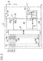
- This handle 2 has a remote control switch 2D in a pad section, besides an existing horn switch 2C, and incorporates thereunder a transceiver circuit 2E, etc. as shown in Fig. 3.
- the transceiver circuit 2E is a circuit for demodulating the encoded signal outputted by the micro-computer 2F to transmit as a radio wave through the antenna 2A, depending on operation of the remote control switch 2D, and has an input end connected to the micro-computer at a front stage.
- the radio wave transmitted by the antenna 2A is set at the same frequency as the radio wave transmitted by the keyless entry apparatus 4.
- a power source line for the transceiver circuit 2E is connected with a switch circuit 2G comprising a transistor T1 and resistances R11, R12 so that the transceiver circuit 2E can be turned on/off by the micro-computer 2F.
- the transceiver circuit 2E shown in Fig. 3 exemplifies an FM modulation type transmitting circuit, it is an existing circuit and no detailed explanations will be especially made.
- the remote control switch 2D is connection-structured by switches S6, S7, S8, S9 ... SZ and resistances R6, R7, R8, R9 ... RZ.
- the structure denoted by a symbol 2H in Fig. 3 is a voltage regulator.
- the remote control switch 2D, the transceiver circuit 2E, and the micro-computer 2F of the handle 2 are respectively connected to a ground pattern 2B.
- the conductor pattern of the printed board is designed such that the antenna 2A is distant from the ground pattern 2B, for example, by 10 [m] or greater, and from the steering shaft 3 penetrated through the center of the column switch 1, for example, by 10 [m] or greater. That is, by separating the antenna 2A from the ground, the signal-receiving sensitivity is made favorable.
- the operation of the above embodiment will be explained.
- a radio wave is transmitted from the keyless entry apparatus 4 outside the vehicle
- the radio wave is received by the antenna 1A of the column switch 1 and be inputted into the transceiver circuit 1F.
- the transceiver circuit 1F wave-detects a high frequency signal to extract an encoded signal carried by the high frequency signal, inputting it to the micro-computer 1H.
- the micro-computer 1H compares the inputted encoded signal with a pre-stored reference code. As a result, if an ID code for the own vehicle is detected, determination is made for the kind of a control code transmitted in combination with the ID code.
- control code represents a keyless entry
- outputting is made for a corresponding encoded signal to the CPU 6B of the control unit 6 and a clock signal. This causes the control unit 6 to output a control signal to a door lock actuator 7E to thereby unlock the door.
- the radio wave is transmitted from the remote control unit 5 within the vehicle, the radio wave is received by the antenna 1A of the column switch 1 and inputted to the transceiver circuit 1F.
- the transceiver circuit 1F wave-detects a high frequency signal to extract an encoded signal carried by the high frequency signal, inputting it to the micro-computer 1H.
- the micro-computer 1H determines the kind of a control code from the inputted encoded signal and a pre-stored reference code to output a corresponding encoded signal to the CPU 6B of the control unit 6 and a clock signal. This causes the control unit 6 to output, for controlling, a control signal to an air-conditioning section 7D or the like.
- the radio wave is transmitted from the handle 2, the radio wave is received by the antenna 1A of the column switch 1 and inputted to the transceiver circuit 1F.
- the transceiver circuit 1F wave-detects a high frequency signal to extract an encoded signal carried by the high frequency signal, inputting it to the micro-computer 1H.
- the micro-computer 1H determines the kind of a control code from the inputted encoded signal and a pre-stored reference code to output an corresponding encoded signal to the CPU 6B of the control unit 6 and a clock signal. This causes the control unit 6 to output, for controlling, a control signal to a had-free section 7A, a display section 7B, a speaker section 7C, and the air-conditioning section 7D or the like.
- this invention is not limited to ones shown by Fig. 1 - Fig. 3, but can be modified in various ways within a range not departing from the gist.
- it may be possible to receive, by the antenna provided in the handle, the radio wave transmitted by the keyless entry apparatus or the remote control unit.
- the modulating method by using the transceiver may adopt a method other than the FM modulating method.
- the column switch is a switch around the vehicular handle, and not limited to the lever switch type one exemplified in Fig. 1.
Landscapes
- Engineering & Computer Science (AREA)
- Remote Sensing (AREA)
- Mechanical Engineering (AREA)
- Computer Security & Cryptography (AREA)
- Radar, Positioning & Navigation (AREA)
- Lock And Its Accessories (AREA)
- Selective Calling Equipment (AREA)
- Fittings On The Vehicle Exterior For Carrying Loads, And Devices For Holding Or Mounting Articles (AREA)
- Support Of Aerials (AREA)
Applications Claiming Priority (3)
| Application Number | Priority Date | Filing Date | Title |
|---|---|---|---|
| JP9189028A JPH1127023A (ja) | 1997-06-30 | 1997-06-30 | 車両用アンテナ装置 |
| JP189028/97 | 1997-06-30 | ||
| JP18902897 | 1997-06-30 |
Publications (3)
| Publication Number | Publication Date |
|---|---|
| EP0889538A2 true EP0889538A2 (de) | 1999-01-07 |
| EP0889538A3 EP0889538A3 (de) | 1999-05-12 |
| EP0889538B1 EP0889538B1 (de) | 2001-11-14 |
Family
ID=16234095
Family Applications (1)
| Application Number | Title | Priority Date | Filing Date |
|---|---|---|---|
| EP98111828A Expired - Lifetime EP0889538B1 (de) | 1997-06-30 | 1998-06-26 | Kraftfahrzeug-Antennenvorrichtung |
Country Status (4)
| Country | Link |
|---|---|
| US (1) | US6078293A (de) |
| EP (1) | EP0889538B1 (de) |
| JP (1) | JPH1127023A (de) |
| DE (1) | DE69802473T2 (de) |
Cited By (2)
| Publication number | Priority date | Publication date | Assignee | Title |
|---|---|---|---|---|
| DE19912674A1 (de) * | 1999-03-20 | 2000-10-05 | Webasto Thermosysteme Gmbh | Anordnung aus Empfänger und Empfangsantenne einer Fernwirkanlage |
| EP1022417A4 (de) * | 1998-06-16 | 2005-01-19 | Matsushita Electric Industrial Co Ltd | Multifunktionsschalter für kraftfahrzeuge |
Families Citing this family (17)
| Publication number | Priority date | Publication date | Assignee | Title |
|---|---|---|---|---|
| JPH11306921A (ja) * | 1998-04-15 | 1999-11-05 | Tokai Rika Co Ltd | レバーコンビネーションスイッチユニット |
| JP2001027062A (ja) | 1999-07-15 | 2001-01-30 | Nippon Seiki Co Ltd | キーレスエントリーシステム |
| US6731020B2 (en) * | 2000-02-28 | 2004-05-04 | Delphi Technologies, Inc. | Column electronics control assembly |
| US6516640B2 (en) | 2000-12-05 | 2003-02-11 | Strattec Security Corporation | Steering column lock apparatus and method |
| US6571587B2 (en) | 2001-01-09 | 2003-06-03 | Strattec Security Corporation | Steering column lock apparatus and method |
| JP4708621B2 (ja) * | 2001-08-13 | 2011-06-22 | クラリオン株式会社 | アンテナ装置及びそれを用いた電子機器 |
| US8301108B2 (en) * | 2002-11-04 | 2012-10-30 | Naboulsi Mouhamad A | Safety control system for vehicles |
| US6812900B2 (en) * | 2001-11-07 | 2004-11-02 | Lear Corporation | Vehicle seating system capable of receiving and transmitting radio frequency signals |
| JP3900912B2 (ja) * | 2001-12-05 | 2007-04-04 | 株式会社豊田自動織機 | 産業車両 |
| ITTO20030756A1 (it) * | 2002-09-30 | 2004-04-01 | Honda Motor Co Ltd | Sistema di chiave elettrica per veicolo. |
| EP1447878A1 (de) * | 2003-02-12 | 2004-08-18 | Hirschmann Electronics GmbH & Co. KG | Antenne für eine Funkzentralverriegelung |
| US7140213B2 (en) | 2004-02-21 | 2006-11-28 | Strattec Security Corporation | Steering column lock apparatus and method |
| US7564415B2 (en) * | 2005-01-28 | 2009-07-21 | Flextronics Automotive Inc. | Antenna system for remote control automotive application |
| TWI276562B (en) * | 2005-03-25 | 2007-03-21 | Delta Electronics Inc | Radio frequency wireless steering wheel |
| JP2006298241A (ja) * | 2005-04-22 | 2006-11-02 | Toyota Motor Corp | 車両用表示装置 |
| USD812587S1 (en) | 2015-04-17 | 2018-03-13 | Skullcandy, Inc. | Portion of a headphone |
| USD768599S1 (en) | 2015-04-17 | 2016-10-11 | Skullcandy, Inc. | Portion of a headphone |
Family Cites Families (7)
| Publication number | Priority date | Publication date | Assignee | Title |
|---|---|---|---|---|
| JPS60117898A (ja) * | 1983-11-29 | 1985-06-25 | Toyota Motor Corp | 操作スイツチ装置 |
| JPS61196080A (ja) * | 1985-02-21 | 1986-08-30 | 日産自動車株式会社 | 無線式利用者識別装置 |
| US5396215A (en) * | 1992-10-28 | 1995-03-07 | Hinkle; Terry A. | Vehicle operation inhibitor control apparatus |
| JP3369305B2 (ja) * | 1994-05-16 | 2003-01-20 | ナイルス部品株式会社 | 車両用ワイヤレスリモコン装置 |
| FR2725674A1 (fr) * | 1994-10-14 | 1996-04-19 | Martins Manuel | Nouveau dispositif de controle d'acces pour vehicule |
| JP3158010B2 (ja) * | 1995-03-31 | 2001-04-23 | 富士通テン株式会社 | 車両用識別装置 |
| US5707262A (en) * | 1996-04-23 | 1998-01-13 | Huntley; Jeffery W. | Wireless trim control system for boat drive |
-
1997
- 1997-06-30 JP JP9189028A patent/JPH1127023A/ja active Pending
-
1998
- 1998-05-21 US US09/082,148 patent/US6078293A/en not_active Expired - Fee Related
- 1998-06-26 EP EP98111828A patent/EP0889538B1/de not_active Expired - Lifetime
- 1998-06-26 DE DE69802473T patent/DE69802473T2/de not_active Expired - Fee Related
Cited By (2)
| Publication number | Priority date | Publication date | Assignee | Title |
|---|---|---|---|---|
| EP1022417A4 (de) * | 1998-06-16 | 2005-01-19 | Matsushita Electric Industrial Co Ltd | Multifunktionsschalter für kraftfahrzeuge |
| DE19912674A1 (de) * | 1999-03-20 | 2000-10-05 | Webasto Thermosysteme Gmbh | Anordnung aus Empfänger und Empfangsantenne einer Fernwirkanlage |
Also Published As
| Publication number | Publication date |
|---|---|
| DE69802473D1 (de) | 2001-12-20 |
| EP0889538B1 (de) | 2001-11-14 |
| DE69802473T2 (de) | 2002-04-11 |
| EP0889538A3 (de) | 1999-05-12 |
| US6078293A (en) | 2000-06-20 |
| JPH1127023A (ja) | 1999-01-29 |
Similar Documents
| Publication | Publication Date | Title |
|---|---|---|
| EP0889538B1 (de) | Kraftfahrzeug-Antennenvorrichtung | |
| US6362771B1 (en) | Garage door opener system for vehicles using manufacturer-supplied equipment | |
| US6127922A (en) | Vehicle security system with remote systems control | |
| US6150926A (en) | Vehicle security system including indicator mounted to window antenna unit and related methods | |
| WO1999066474A1 (en) | Vehicle communication system with trainable transmitter | |
| US5847671A (en) | Arrangement of a vehicle auxiliary heater with a regulating device and control unit inside a vehicle | |
| US4897643A (en) | Vehicular electronic equipment with door lock and side window antenna | |
| GB2387283A (en) | A radio receiving/transmitting component mounted in a car headrest | |
| JP3369305B2 (ja) | 車両用ワイヤレスリモコン装置 | |
| US6037859A (en) | Vehicle security system including control switch mounted to window antenna unit and associated methods | |
| KR19990081486A (ko) | 자동차의 원격 수신장치 | |
| EP1122969B1 (de) | Schlüsselloses Zugangskontrollsystem | |
| US6274946B1 (en) | Lever combination switch unit | |
| GB2327814A (en) | Remote control alarm using power lead as antenna | |
| JP4096408B2 (ja) | 自動車用コンビネーションスイッチ | |
| JP3253101B2 (ja) | 車両用リモートコントロール装置 | |
| US6211578B1 (en) | Instrumentation for vehicles | |
| US6801119B1 (en) | Programmer for vehicle security systems and related methods | |
| JP3216112B2 (ja) | 車両用計器装置 | |
| WO2005017850A1 (en) | Control system and method for automotive decorative lighting | |
| JPH10157534A (ja) | 車両用アンテナ装置 | |
| JP4587599B2 (ja) | 電波受信機 | |
| JP4253099B2 (ja) | キーレスエントリーシステム | |
| JPH10329578A (ja) | 車両用計器装置 | |
| JPH0953351A (ja) | 車両用電波錠装置 |
Legal Events
| Date | Code | Title | Description |
|---|---|---|---|
| PUAI | Public reference made under article 153(3) epc to a published international application that has entered the european phase |
Free format text: ORIGINAL CODE: 0009012 |
|
| AK | Designated contracting states |
Kind code of ref document: A2 Designated state(s): DE FR GB |
|
| AX | Request for extension of the european patent |
Free format text: AL;LT;LV;MK;RO;SI |
|
| PUAL | Search report despatched |
Free format text: ORIGINAL CODE: 0009013 |
|
| AK | Designated contracting states |
Kind code of ref document: A3 Designated state(s): AT BE CH CY DE DK ES FI FR GB GR IE IT LI LU MC NL PT SE |
|
| AX | Request for extension of the european patent |
Free format text: AL;LT;LV;MK;RO;SI |
|
| 17P | Request for examination filed |
Effective date: 19990526 |
|
| 17Q | First examination report despatched |
Effective date: 19991203 |
|
| AKX | Designation fees paid |
Free format text: DE FR GB |
|
| GRAG | Despatch of communication of intention to grant |
Free format text: ORIGINAL CODE: EPIDOS AGRA |
|
| GRAG | Despatch of communication of intention to grant |
Free format text: ORIGINAL CODE: EPIDOS AGRA |
|
| GRAH | Despatch of communication of intention to grant a patent |
Free format text: ORIGINAL CODE: EPIDOS IGRA |
|
| GRAH | Despatch of communication of intention to grant a patent |
Free format text: ORIGINAL CODE: EPIDOS IGRA |
|
| GRAA | (expected) grant |
Free format text: ORIGINAL CODE: 0009210 |
|
| AK | Designated contracting states |
Kind code of ref document: B1 Designated state(s): DE FR GB |
|
| REF | Corresponds to: |
Ref document number: 69802473 Country of ref document: DE Date of ref document: 20011220 |
|
| REG | Reference to a national code |
Ref country code: GB Ref legal event code: IF02 |
|
| PLBE | No opposition filed within time limit |
Free format text: ORIGINAL CODE: 0009261 |
|
| STAA | Information on the status of an ep patent application or granted ep patent |
Free format text: STATUS: NO OPPOSITION FILED WITHIN TIME LIMIT |
|
| 26N | No opposition filed | ||
| PGFP | Annual fee paid to national office [announced via postgrant information from national office to epo] |
Ref country code: FR Payment date: 20060608 Year of fee payment: 9 |
|
| PGFP | Annual fee paid to national office [announced via postgrant information from national office to epo] |
Ref country code: GB Payment date: 20060621 Year of fee payment: 9 |
|
| PGFP | Annual fee paid to national office [announced via postgrant information from national office to epo] |
Ref country code: DE Payment date: 20060622 Year of fee payment: 9 |
|
| GBPC | Gb: european patent ceased through non-payment of renewal fee |
Effective date: 20070626 |
|
| REG | Reference to a national code |
Ref country code: FR Ref legal event code: ST Effective date: 20080229 |
|
| PG25 | Lapsed in a contracting state [announced via postgrant information from national office to epo] |
Ref country code: DE Free format text: LAPSE BECAUSE OF NON-PAYMENT OF DUE FEES Effective date: 20080101 |
|
| PG25 | Lapsed in a contracting state [announced via postgrant information from national office to epo] |
Ref country code: GB Free format text: LAPSE BECAUSE OF NON-PAYMENT OF DUE FEES Effective date: 20070626 |
|
| PG25 | Lapsed in a contracting state [announced via postgrant information from national office to epo] |
Ref country code: FR Free format text: LAPSE BECAUSE OF NON-PAYMENT OF DUE FEES Effective date: 20070702 |