EP0889553A2 - Steckverbinder - Google Patents
Steckverbinder Download PDFInfo
- Publication number
- EP0889553A2 EP0889553A2 EP98112353A EP98112353A EP0889553A2 EP 0889553 A2 EP0889553 A2 EP 0889553A2 EP 98112353 A EP98112353 A EP 98112353A EP 98112353 A EP98112353 A EP 98112353A EP 0889553 A2 EP0889553 A2 EP 0889553A2
- Authority
- EP
- European Patent Office
- Prior art keywords
- contact
- strain relief
- line
- elements
- contact carrier
- Prior art date
- Legal status (The legal status is an assumption and is not a legal conclusion. Google has not performed a legal analysis and makes no representation as to the accuracy of the status listed.)
- Granted
Links
- 230000000149 penetrating effect Effects 0.000 claims description 8
- 238000009413 insulation Methods 0.000 abstract description 12
- 238000003780 insertion Methods 0.000 abstract description 2
- 230000037431 insertion Effects 0.000 abstract description 2
- 239000011810 insulating material Substances 0.000 abstract 1
- 238000006073 displacement reaction Methods 0.000 description 9
- 238000004519 manufacturing process Methods 0.000 description 8
- 239000013307 optical fiber Substances 0.000 description 5
- 239000004020 conductor Substances 0.000 description 2
- 230000000694 effects Effects 0.000 description 2
- 238000010521 absorption reaction Methods 0.000 description 1
- 239000011324 bead Substances 0.000 description 1
- 230000006378 damage Effects 0.000 description 1
- 238000005516 engineering process Methods 0.000 description 1
- 239000000463 material Substances 0.000 description 1
- 230000003287 optical effect Effects 0.000 description 1
- 230000035515 penetration Effects 0.000 description 1
- 230000002093 peripheral effect Effects 0.000 description 1
- 238000007789 sealing Methods 0.000 description 1
- 239000004753 textile Substances 0.000 description 1
Images


Classifications
-
- H—ELECTRICITY
- H01—ELECTRIC ELEMENTS
- H01R—ELECTRICALLY-CONDUCTIVE CONNECTIONS; STRUCTURAL ASSOCIATIONS OF A PLURALITY OF MUTUALLY-INSULATED ELECTRICAL CONNECTING ELEMENTS; COUPLING DEVICES; CURRENT COLLECTORS
- H01R13/00—Details of coupling devices of the kinds covered by groups H01R12/70 or H01R24/00 - H01R33/00
- H01R13/58—Means for relieving strain on wire connection, e.g. cord grip, for avoiding loosening of connections between wires and terminals within a coupling device terminating a cable
- H01R13/585—Grip increasing with strain force
-
- G—PHYSICS
- G02—OPTICS
- G02B—OPTICAL ELEMENTS, SYSTEMS OR APPARATUS
- G02B6/00—Light guides; Structural details of arrangements comprising light guides and other optical elements, e.g. couplings
- G02B6/24—Coupling light guides
- G02B6/36—Mechanical coupling means
- G02B6/38—Mechanical coupling means having fibre to fibre mating means
- G02B6/3807—Dismountable connectors, i.e. comprising plugs
- G02B6/3887—Anchoring optical cables to connector housings, e.g. strain relief features
- G02B6/3888—Protection from over-extension or over-compression
Definitions
- the invention relates to a connector, preferably with a cylindrical one Contact carrier, with a screwable preferably on the contact carrier Union sleeve, with at least one contact element carried by the contact carrier and with at least one strain relief element, the contact carrier for receiving at least one line at least one in the line connection direction has extending recess.
- Connectors of the type from which the connection originates are off DE 31 50 568 C1 and DE 32 20 006 C1 are known.
- Connectors of the type from which the connection originates, for example, are off DE 31 50 568 C1 and DE 32 20 006 C1 are known.
- Connectors is a strain relief element between the contact carrier and the union sleeve arranged sealing and strain relief ring known by screwing on the sleeve with an internal thread a bead present in the cap sleeve in the insertion area of one Plurality of leads leading cable against the surface of the cable as well is pressed against the rear end face of the contact carrier and so one Friction between cable and connector generated.
- annular pressure body the outer diameter of which is approximately the inner diameter the sleeve and its inner diameter approximately the outer diameter of the cable carrying a plurality of lines corresponds to this pressure body is feathered at its end facing away from the contact carrier is so that after screwing the union sleeve through to the cable entry side pressed towards the conical inner wall by such an amount can be that he presses an elastic ring against the cable and thus in turn ensures a frictional connection between the cable and the connector.
- the contact carrier of the known connector has several recesses Inclusion of one line each, with an insulation displacement terminal in each recess is arranged for contacting the respective line.
- the union sleeve is designed in the known connectors so that when screwing the Union sleeve on the contact carrier on the front of the insulation displacement terminals each overlying cables are pressed into the insulation displacement terminals and thus contacted become.
- the pressure body known from DE 32 20 006 C1 instructs its end facing the contact carrier is assigned to the recesses Fingers that are shaped so that they are pressed in elastically by a certain amount to let. This is where the cables are pressed into the insulation displacement terminals not directly via the internal thread of the union sleeve, but indirectly via the fingers of the pressure element, which are pressed in elastically by the internal thread.
- the invention is therefore based on the object known from the prior art To design and further develop connectors so that the Strain relief elements are designed such that they are as simple as possible and Fast assembly of cables connected to the connector a reduced size at the same time.
- the strain relief elements are arranged on the long sides of the recesses are and each have at least one protruding into the respective recess, at least penetrating into a casing of a line introduced into the recess Have tip.
- the strain relief elements designed in this way of an inventive Connectors now enable quick and easy
- the associated cable is assembled simply by sliding it on or screwing it on the union sleeve, causing the tips of the strain relief elements in the casing penetrate the line and ensure strain relief.
- the Strain relief elements according to the invention in the recess provided anyway to accommodate the lines, the outer diameter of the invention Connector for example up to the diameter of the lines comprehensive cable can be reduced.
- the in the sheath of the lines penetrating tips ensure sufficient strain relief because the sheathing remains intact to one point and the risk of stripping the cable does not exist under tensile loads such as insulation displacement terminals.
- strain relief effect of the strain relief elements can thereby be further increased be that the strain relief elements each have several tips in the mounting direction the sleeve has increasing length.
- the increase in Length of the tips is advantageous in that the screwing or plugging on the union sleeve is thereby simplified. That several in the casing tips penetrated a line the possibility of a higher force absorption give no special explanation.
- Such a configuration of the tips of the strain relief elements is particularly advantageous for sheathing with a textile structure, because in such a case the tips get caught in the sheathing material can.
- the invention Connector advantageously designed in that the contact element for contacting the line has a contact tip penetrating into the line in the longitudinal direction having. This axial contact element enables compared to contacting with insulation piercing a further reduction in the diameter of the invention Connector.
- the invention To position the line, in the case of an electrical line relative to the Contact tip and in the case of an optical fiber relative to the ends of the optical fiber opposing optical elements to improve, is the invention Connector designed in that on the contact elements facing end of a recess adapted to the cross section of the line Deepening is provided. This deepening leads the leadership such that it is optimally brought up to its counterpart in the connector.
- the strain relief elements laterally in mounting recesses running in the line connection direction of the contact carrier and these are in the assembled state of the connector secured by the union sleeve and the lines, there is a special simple and inexpensive manufacture of the connector according to the invention.
- Connector is that the contact elements laterally in mounting recesses running in the line connection direction in the contact carrier can be inserted and in the assembled state of the connector through the union sleeve are secured.
- the contact elements and / or the strain relief elements in line connection directions Have stop surfaces and by assigned stop surfaces of the respective mounting recesses of the contact carrier in line connection direction are secured, it is ensured that the contact elements and the strain relief elements the attacking forces by positive locking in the contact carrier can initiate without shedding, for example, in the contact carrier are.
- each contact elements and strain relief elements assigned to a line are made in one piece.
- Fig. 1 is a contact carrier 1 of an embodiment of an inventive Connector shown in perspective view.
- the contact carrier 1 has in Embodiment an external thread 2 on the one shown in Fig. 2 Union sleeve 3 can be screwed on.
- an external thread 2 on the one shown in Fig. 2 Union sleeve 3 can be screwed on.
- the union sleeve 3 is only pushed onto the contact carrier and in the end position locked. This alternative is particularly conceivable in the event that Sliding the union sleeve onto the contact carrier only results in low forces.
- the contact carrier 1 shown in Fig. 1 carries a total of five contact elements 4 and five strain relief elements 5, the latter in the illustration in FIG. 1 only one is visible. As can be clearly seen in Fig. 1, the contact carrier 1 for receiving a total of five lines 6, of which only four in FIG. 1 are shown, five recesses 7 running in the line connection direction.
- Fig. 1 can be clearly seen from the illustrated strain relief element 5, that this in a recess 7 on one of the long sides 8,9 of the recess 7 is arranged and a total of three protruding into this recess 7, at line 6 introduced into the recess 7 into a casing 10 of a line 6 has penetrating tips 11.
- the tips 11 shown in Fig. 1 do not have one in the mounting direction shown sleeve on significantly increasing length.
- the tips shown 11 are not in the embodiment of a connector according to the invention formed as barbs, but viewed from the side form an isosceles Triangle where the sides of equal length form an angle of approximately Include 25 °.
- the strain relief elements 5 in each case on a longitudinal side 8 of the axis of the contact carrier 1 Contact carrier 1 arranged.
- the respective line 6 when screwing the union sleeve, not shown, perpendicular to the Tips 11 pressed.
- one or more strain relief elements in the adjacent recesses 7 facing long sides 9 are arranged.
- the respective Line 6 when screwing in the union sleeve, not shown in Fig. 1 an angle to that provided according to the alternative, not shown Strain relief elements pressed.
- the contact carrier 1 is such formed that the recesses 7 are open on the circumference.
- the peripheral side of the recesses 7 by a not shown,
- Such a measure would by screwing the union sleeve (not shown in FIG. 1) onto the contact carrier 1 by friction of the thread of the union sleeve 3, not shown the sheathing 10 of a line 6 resulting force component, which is a proper Penetration of the tips 11 in the casing 10 impair can, greatly reduced.
- Fig. 1 it can also be seen that in the contact carrier 1 laterally in the line connection direction extending mounting recesses 15 are provided, in which the Contact elements 4 and the strain relief elements 5 can be inserted, the strain relief elements 5 in the assembled state of the connector by the in Fig. 1st Union sleeve, not shown, and the respective lines 6 and the contact elements 4 are secured only in the radial direction by the union sleeve.
- radially outwards Acting forces are therefore not special measures when attaching the Contact elements 4 in the mounting recess 15 necessary.
- Fig. 2 shows a perspective view of the embodiment of an inventive Connector, here compared to the illustration in Fig. 1 on the one hand the sleeve 3 is shown and on the other hand in all the recesses 7 of the contact carrier 1 all five lines 6 of a cable 16 are inserted, so that only screw the sleeve 3 onto the contact carrier 1.
- FIG. 3 the embodiment of a connector according to the invention is with screwed union sleeve 3 shown from the direction of outgoing lines 6.
- FIG. 4 also shows the embodiment of a connector according to the invention with screwed union sleeve 3, but from the direction of the contact elements 4 and with a connected cable 16.
- FIG. 4 is special clearly recognizable that the embodiment of a connector according to the invention has an outer diameter which corresponds to that of the cable 16. A such a compact design of the connector was previously in the prior art not conceivable.
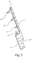
- Fig. 5 is finally shown what is not apparent in Figs. 1 to 4 that the in each case associated with a line, not shown, contact elements 4 and Strain relief elements 5 are made in one piece.
- this is during production of the connector according to the invention is advantageous because the number of parts is reduced, and on the other hand also advantageous from an electrical point of view, since at least the longest of the tips 11, in Fig. 5 at the upper end of the strain relief element 5 arranged, not only in the casing or insulation of not here shown line penetrates, but beyond to the head of the line penetrates and can either make the electrical contact alone or, as in the illustrated embodiment, the one produced via the contact tip 12 electrical contact improved.
- the longest tip 11 in the event that the connector receives lines in the form of optical fibers do not penetrate through the sheath of the cable into the optical fiber, otherwise the light signal is caused by destruction of the optical fiber would be at least excessively dampened.
- Fig. 5 it can also be seen that the one-piece design of the contact element 4 and the strain relief element 5 stop surfaces 17 and 18 in the cable connection direction have, which are not shown, in the respective, in particular In Fig. 1 recognizable mounting recess 15 provided, assigned stop surfaces cooperates such that the contact elements made in one piece 4 and strain relief elements 5 form-fitting in the line connection direction are secured. Due to the positive locking of the one-piece design Contact elements 4 and strain relief elements 5 both in the radial direction the union sleeve, not shown in Fig.
Landscapes
- Physics & Mathematics (AREA)
- General Physics & Mathematics (AREA)
- Optics & Photonics (AREA)
- Connector Housings Or Holding Contact Members (AREA)
- Details Of Connecting Devices For Male And Female Coupling (AREA)
- Coupling Device And Connection With Printed Circuit (AREA)
- Earth Drilling (AREA)
- Piezo-Electric Or Mechanical Vibrators, Or Delay Or Filter Circuits (AREA)
- Quick-Acting Or Multi-Walled Pipe Joints (AREA)
Abstract
Description
- Fig. 1
- eine perspektivische Ansicht eines Kontaktträgers eines Ausführungsbeispiels eines erfindungsgemäßen Steckverbinders,
- Fig. 2
- eine perspektivische Ansicht des Ausführungsbeispiels eines erfindungsgemäßen Steckverbinders mit einem angeschlossenen Kabel und mit einer abgenonunenen Überwurfhülse,
- Fig. 3
- eine perspektivische Ansicht des Ausführungsbeispiels eines erfindungsgemäßen Steckverbinders im montierten Zustand mit zur Vereinfachung der Darstellung gekürzten Leitungen,
- Fig. 4
- eine perspektivische Ansicht des Ausführungsbeispiels eines erfindungsgemäßen Steckverbinders komplett montiert und
- Fig. 5
- eine perspektivische Ansicht eines kombinierten Kontakt- und Zugentlastungselementes des Ausführungsbeispiels eines erfindungsgemäßen Steckverbinders.
Claims (10)
- Steckverbinder, mit einem vorzugsweise zylinderförmigen Kontaktträger (1), mit einer vorzugsweise auf den Kontaktträger (1) aufschraubbaren Überwurfhülse (3), mit mindestens einem von dem Kontaktträger (1) getragenen Kontaktelement (4) und mit mindestens einem Zugentlastungselement (5), wobei der Kontaktträger (1) zur Aufnahme mindestens einer Leitung (6) mindestens eine in Leitungsanschlußrichtung verlaufende Ausnehmung (7) aufweist, dadurch gekennzeichnet, daß die Zugentlastungselemente (5) an den Längsseiten (8, 9) der Ausnehmungen (7) angeordnet sind und jeweils mindestens eine in die jeweilige Ausnehmung (7) hineinragende, mindestens in eine Ummantelung (10) einer in die Ausnehmung eingebrachten Leitung (6) eindringende Spitze (11) aufweisen.
- Steckverbinder nach Anspruch 1, dadurch gekennzeichnet, daß die Zugentlastungselemente (5) jeweils mehrere Spitzen (11) mit in Montagerichtung der Überwurfhülse (3) zunehmender Länge aufweisen.
- Steckverbinder nach Anspruch 1 oder 2, dadurch gekennzeichnet, daß mindestens ein Teil der Spitzen (11) der Zugentlastungselemente (5) nach Art eines Widerhakens entgegen der Zugrichtung hinterschnitten sind.
- Steckverbinder nach einem der Ansprüche 1 bis 3, dadurch gekennzeichnet, daß die Zugentlastungselemente (5) bei einem zylinderförmigen Kontaktträger (1) an einer, der Zylinderachse zugewandten Längsseite (8) der jeweiligen Ausnehmung (7) angeordnet sind.
- Steckverbinder nach einem der Ansprüche 1 bis 4, dadurch gekennzeichnet, daß das Kontaktelement (4) zur Kontaktierung der Leitung (6) eine in Längsrichtung in die Leitung (6) eindringende Kontaktspitze (12) aufweist
- Steckverbinder nach einem der Ansprüche 1 bis 5, dadurch gekennzeichnet, daß an dem den Kontaktelementen (4) zugewandten Ende einer Ausnehmung (7) eine an den Querschnitt der Leitung (6) angepaßte Vertiefung (14) vorgesehen ist.
- Steckverbinder nach einem der Ansprüche 1 bis 6, dadurch gekennzeichnet, daß die Zugentlastungselemente (5) seitlich in in Leitungsanschlußrichtung verlaufende Montageausnehmungen (15) des Kontaktträgers (1) einlegbar sind und im montierten Zustand des Steckverbinders durch die Überwurfhülse (3) und die Leitungen (6) gesichert sind.
- Steckverbinder nach einem der Ansprüche 1 bis 7, dadurch gekennzeichnet, daß die Kontaktelemente seitlich in in Leitungsanschlußrichtung verlaufende Montageausnehmungen (15) im Kontaktträger (1) einlegbar sind und im montierten Zustand des Steckverbinders durch die Überwurfhülse (3) gesichert sind.
- Steckverbinder nach Anspruch 7 oder 8, dadurch gekennzeichnet, daß die Kontaktelemente (4) und/oder die Zugentlastungselemente (5) in Leitungsanschlußrichtung Anschlagflächen (17, 18) aufweisen und durch zugeordnete Anschlagflächen der jeweiligen Montageausnehmungen (15) des Kontaktträgers (1) in Leitungsanschlußrichtung gesichert sind.
- Steckverbinder nach einem der Ansprüche 1 bis 9, dadurch gekennzeichnet, daß die jeweils einer Leitung (6) zugeordneten Kontaktelemente (4) und Zugentlastungselemente (5) einstückig ausgeführt sind.
Applications Claiming Priority (2)
| Application Number | Priority Date | Filing Date | Title |
|---|---|---|---|
| DE19728506 | 1997-07-03 | ||
| DE19728506A DE19728506C2 (de) | 1997-07-03 | 1997-07-03 | Steckverbinder |
Publications (3)
| Publication Number | Publication Date |
|---|---|
| EP0889553A2 true EP0889553A2 (de) | 1999-01-07 |
| EP0889553A3 EP0889553A3 (de) | 1999-12-29 |
| EP0889553B1 EP0889553B1 (de) | 2006-12-20 |
Family
ID=7834581
Family Applications (1)
| Application Number | Title | Priority Date | Filing Date |
|---|---|---|---|
| EP98112353A Expired - Lifetime EP0889553B1 (de) | 1997-07-03 | 1998-07-03 | Steckverbinder |
Country Status (4)
| Country | Link |
|---|---|
| EP (1) | EP0889553B1 (de) |
| AT (1) | ATE349083T1 (de) |
| DE (2) | DE19728506C2 (de) |
| ES (1) | ES2277370T3 (de) |
Family Cites Families (7)
| Publication number | Priority date | Publication date | Assignee | Title |
|---|---|---|---|---|
| DE961904C (de) * | 1954-08-25 | 1957-04-11 | Academy Electrical Products Co | Steckdose |
| DE3150568C1 (de) * | 1981-12-21 | 1983-02-24 | Siemens AG, 1000 Berlin und 8000 München | Kabelanschlußelement |
| DE3220006C1 (de) * | 1982-05-27 | 1983-10-27 | Siemens AG, 1000 Berlin und 8000 München | Kabelanschlußelement |
| DE3461405D1 (en) * | 1983-06-20 | 1987-01-08 | Allied Corp | A terminal and method of electrical connection to the center conductor of an insulated wire |
| AU667541B2 (en) * | 1992-07-03 | 1996-03-28 | Amphenol Corporation | Cord grip arrangement |
| GB9500976D0 (en) * | 1995-01-19 | 1995-03-08 | Europanasonic Uk Limited | Improvements in or relating to electric connectors |
| US5599202A (en) * | 1996-01-22 | 1997-02-04 | Electrical Wiring Device Company, Inc. | Strain relief electrical connector |
-
1997
- 1997-07-03 DE DE19728506A patent/DE19728506C2/de not_active Expired - Fee Related
-
1998
- 1998-07-03 DE DE59813849T patent/DE59813849D1/de not_active Expired - Fee Related
- 1998-07-03 AT AT98112353T patent/ATE349083T1/de active
- 1998-07-03 ES ES98112353T patent/ES2277370T3/es not_active Expired - Lifetime
- 1998-07-03 EP EP98112353A patent/EP0889553B1/de not_active Expired - Lifetime
Also Published As
| Publication number | Publication date |
|---|---|
| ATE349083T1 (de) | 2007-01-15 |
| DE19728506C2 (de) | 2002-02-14 |
| DE19728506A1 (de) | 1999-02-04 |
| DE59813849D1 (de) | 2007-02-01 |
| EP0889553A3 (de) | 1999-12-29 |
| ES2277370T3 (es) | 2007-07-01 |
| EP0889553B1 (de) | 2006-12-20 |
Similar Documents
| Publication | Publication Date | Title |
|---|---|---|
| EP0684666B1 (de) | Mehrpoliger Kabelsteckverbinder | |
| EP1096605B1 (de) | Kabelanschluss- oder -verbindungseinrichtung | |
| EP2365586B1 (de) | Kabelsteckverbinder, insbesondere mehrpoliger Kabelsteckverbinder | |
| DE4140227A1 (de) | Vorrichtung fuer den anschluss eines kabelendes | |
| EP3776751B1 (de) | Steckeranordnung für datenkabel | |
| DE19738517C1 (de) | Kabelverschraubung für Erdungs- oder Abschirmkabel mit einem gegen das Kabel preßbaren Klemmeinsatz | |
| EP3152809A2 (de) | Elektrisches gerät | |
| EP1239550A1 (de) | Steckverbinder | |
| EP0963020A1 (de) | Halterung für längliche Körper mit elektrischer Abschirmung | |
| EP1180823B1 (de) | Kabelanschluss- oder -verbindungseinrichtung | |
| DE102008019758B3 (de) | Anschlussvorrichtung | |
| DE202011002287U1 (de) | Kabelverschraubung für abgeschirmte Leitungen | |
| EP1467441A2 (de) | Schnellanschliessbare Steckverbindung in Spannzangentechnik | |
| DE102019132495A1 (de) | Abschirmungsanordnung und Verfahren zur Montage einer Abschirmungsanordnung | |
| EP1158611A2 (de) | Kabelsteckverbinder | |
| DE69109379T2 (de) | Steckverbinder für Mehrleiterkabel. | |
| EP0889553B1 (de) | Steckverbinder | |
| EP2731204B1 (de) | Verbinder mit Zugentlastungsvorrichtung | |
| DE19830148C5 (de) | Anschlußelement für ein Lichtwellenleiterkabel | |
| DE102006046181B4 (de) | Zugentlastungsvorrichtung für ein Glasfaserkabel | |
| DE19631090C2 (de) | Kabelanschluß für ein Schweißkabel | |
| EP1632009B1 (de) | Kontaktelement und komplementäre leitungskammer für einen stecker oder eine buchse in schneidklemmtechnik | |
| DE29722987U1 (de) | Kabelverschraubung für Kabel mit Abschirmummantelung | |
| EP1598684A2 (de) | An einem zugverstärkten Kabel montierte Steckeranordnung | |
| DE102020131734A1 (de) | Leuchtenklemme mit Verschlusstülle |
Legal Events
| Date | Code | Title | Description |
|---|---|---|---|
| PUAI | Public reference made under article 153(3) epc to a published international application that has entered the european phase |
Free format text: ORIGINAL CODE: 0009012 |
|
| AK | Designated contracting states |
Kind code of ref document: A2 Designated state(s): AT BE CH DE ES FR GB LI LU NL |
|
| AX | Request for extension of the european patent |
Free format text: AL;LT;LV;MK;RO;SI |
|
| RIN1 | Information on inventor provided before grant (corrected) |
Inventor name: BRAND, JUERGEN Inventor name: REIBKE; HEINZ Inventor name: BERG, ROLAND Inventor name: BEHR, THORSTEN |
|
| PUAL | Search report despatched |
Free format text: ORIGINAL CODE: 0009013 |
|
| AK | Designated contracting states |
Kind code of ref document: A3 Designated state(s): AT BE CH CY DE DK ES FI FR GB GR IE IT LI LU MC NL PT SE |
|
| AX | Request for extension of the european patent |
Free format text: AL;LT;LV;MK;RO;SI |
|
| RIC1 | Information provided on ipc code assigned before grant |
Free format text: 7H 01R 13/585 A, 7H 01R 13/512 B, 7H 01R 4/50 B, 7G 02B 6/38 B, 7H 01R 13/59 B |
|
| 17P | Request for examination filed |
Effective date: 20000529 |
|
| AKX | Designation fees paid |
Free format text: AT BE CH DE ES FR GB LI LU NL |
|
| RAP1 | Party data changed (applicant data changed or rights of an application transferred) |
Owner name: PHOENIX CONTACT GMBH & CO. KG |
|
| RIN1 | Information on inventor provided before grant (corrected) |
Inventor name: NORDHOFF, ANDREAS Inventor name: METZGER, ANDREAS |
|
| 17Q | First examination report despatched |
Effective date: 20040609 |
|
| GRAP | Despatch of communication of intention to grant a patent |
Free format text: ORIGINAL CODE: EPIDOSNIGR1 |
|
| GRAS | Grant fee paid |
Free format text: ORIGINAL CODE: EPIDOSNIGR3 |
|
| GRAA | (expected) grant |
Free format text: ORIGINAL CODE: 0009210 |
|
| AK | Designated contracting states |
Kind code of ref document: B1 Designated state(s): AT BE CH DE ES FR GB LI LU NL |
|
| REG | Reference to a national code |
Ref country code: GB Ref legal event code: FG4D Free format text: NOT ENGLISH |
|
| REG | Reference to a national code |
Ref country code: CH Ref legal event code: EP |
|
| REF | Corresponds to: |
Ref document number: 59813849 Country of ref document: DE Date of ref document: 20070201 Kind code of ref document: P |
|
| GBT | Gb: translation of ep patent filed (gb section 77(6)(a)/1977) |
Effective date: 20070117 |
|
| REG | Reference to a national code |
Ref country code: CH Ref legal event code: NV Representative=s name: KELLER & PARTNER PATENTANWAELTE AG |
|
| ET | Fr: translation filed | ||
| REG | Reference to a national code |
Ref country code: ES Ref legal event code: FG2A Ref document number: 2277370 Country of ref document: ES Kind code of ref document: T3 |
|
| PLBE | No opposition filed within time limit |
Free format text: ORIGINAL CODE: 0009261 |
|
| STAA | Information on the status of an ep patent application or granted ep patent |
Free format text: STATUS: NO OPPOSITION FILED WITHIN TIME LIMIT |
|
| 26N | No opposition filed |
Effective date: 20070921 |
|
| PGFP | Annual fee paid to national office [announced via postgrant information from national office to epo] |
Ref country code: DE Payment date: 20090912 Year of fee payment: 12 |
|
| PG25 | Lapsed in a contracting state [announced via postgrant information from national office to epo] |
Ref country code: DE Free format text: LAPSE BECAUSE OF NON-PAYMENT OF DUE FEES Effective date: 20110201 |
|
| REG | Reference to a national code |
Ref country code: DE Ref legal event code: R119 Ref document number: 59813849 Country of ref document: DE Effective date: 20110201 |
|
| REG | Reference to a national code |
Ref country code: CH Ref legal event code: PCAR Free format text: NEW ADDRESS: EIGERSTRASSE 2 POSTFACH, 3000 BERN 14 (CH) |
|
| REG | Reference to a national code |
Ref country code: FR Ref legal event code: PLFP Year of fee payment: 18 |
|
| PGFP | Annual fee paid to national office [announced via postgrant information from national office to epo] |
Ref country code: LU Payment date: 20150724 Year of fee payment: 18 |
|
| PGFP | Annual fee paid to national office [announced via postgrant information from national office to epo] |
Ref country code: NL Payment date: 20150723 Year of fee payment: 18 |
|
| PGFP | Annual fee paid to national office [announced via postgrant information from national office to epo] |
Ref country code: CH Payment date: 20150723 Year of fee payment: 18 Ref country code: GB Payment date: 20150723 Year of fee payment: 18 Ref country code: ES Payment date: 20150713 Year of fee payment: 18 |
|
| PGFP | Annual fee paid to national office [announced via postgrant information from national office to epo] |
Ref country code: AT Payment date: 20150727 Year of fee payment: 18 Ref country code: BE Payment date: 20150723 Year of fee payment: 18 Ref country code: FR Payment date: 20150727 Year of fee payment: 18 |
|
| PG25 | Lapsed in a contracting state [announced via postgrant information from national office to epo] |
Ref country code: BE Free format text: LAPSE BECAUSE OF NON-PAYMENT OF DUE FEES Effective date: 20160731 |
|
| REG | Reference to a national code |
Ref country code: CH Ref legal event code: PL |
|
| REG | Reference to a national code |
Ref country code: NL Ref legal event code: MM Effective date: 20160801 |
|
| REG | Reference to a national code |
Ref country code: AT Ref legal event code: MM01 Ref document number: 349083 Country of ref document: AT Kind code of ref document: T Effective date: 20160703 |
|
| GBPC | Gb: european patent ceased through non-payment of renewal fee |
Effective date: 20160703 |
|
| PG25 | Lapsed in a contracting state [announced via postgrant information from national office to epo] |
Ref country code: FR Free format text: LAPSE BECAUSE OF NON-PAYMENT OF DUE FEES Effective date: 20160801 Ref country code: LI Free format text: LAPSE BECAUSE OF NON-PAYMENT OF DUE FEES Effective date: 20160731 Ref country code: CH Free format text: LAPSE BECAUSE OF NON-PAYMENT OF DUE FEES Effective date: 20160731 Ref country code: NL Free format text: LAPSE BECAUSE OF NON-PAYMENT OF DUE FEES Effective date: 20160801 |
|
| REG | Reference to a national code |
Ref country code: FR Ref legal event code: ST Effective date: 20170331 |
|
| PG25 | Lapsed in a contracting state [announced via postgrant information from national office to epo] |
Ref country code: GB Free format text: LAPSE BECAUSE OF NON-PAYMENT OF DUE FEES Effective date: 20160703 Ref country code: AT Free format text: LAPSE BECAUSE OF NON-PAYMENT OF DUE FEES Effective date: 20160703 |
|
| PG25 | Lapsed in a contracting state [announced via postgrant information from national office to epo] |
Ref country code: LU Free format text: LAPSE BECAUSE OF NON-PAYMENT OF DUE FEES Effective date: 20160703 |
|
| PG25 | Lapsed in a contracting state [announced via postgrant information from national office to epo] |
Ref country code: ES Free format text: LAPSE BECAUSE OF NON-PAYMENT OF DUE FEES Effective date: 20160704 |
|
| REG | Reference to a national code |
Ref country code: ES Ref legal event code: FD2A Effective date: 20181119 |