EP0889560A1 - Méthode et unité pour passer des contacts à un appareil de traitement de contacts - Google Patents
Méthode et unité pour passer des contacts à un appareil de traitement de contacts Download PDFInfo
- Publication number
- EP0889560A1 EP0889560A1 EP97810726A EP97810726A EP0889560A1 EP 0889560 A1 EP0889560 A1 EP 0889560A1 EP 97810726 A EP97810726 A EP 97810726A EP 97810726 A EP97810726 A EP 97810726A EP 0889560 A1 EP0889560 A1 EP 0889560A1
- Authority
- EP
- European Patent Office
- Prior art keywords
- contact
- transfer unit
- crimping
- carrier strip
- transfer
- Prior art date
- Legal status (The legal status is an assumption and is not a legal conclusion. Google has not performed a legal analysis and makes no representation as to the accuracy of the status listed.)
- Granted
Links
- 238000000034 method Methods 0.000 title claims description 20
- 238000012545 processing Methods 0.000 title claims description 16
- 238000012546 transfer Methods 0.000 claims abstract description 65
- 238000002788 crimping Methods 0.000 claims abstract description 60
- 238000005476 soldering Methods 0.000 claims abstract description 4
- 238000006073 displacement reaction Methods 0.000 claims description 19
- 239000004020 conductor Substances 0.000 claims description 7
- 238000009413 insulation Methods 0.000 claims description 7
- 238000000926 separation method Methods 0.000 claims description 5
- 230000008878 coupling Effects 0.000 claims 1
- 238000010168 coupling process Methods 0.000 claims 1
- 238000005859 coupling reaction Methods 0.000 claims 1
- 230000000694 effects Effects 0.000 claims 1
- 230000002996 emotional effect Effects 0.000 claims 1
- 238000002955 isolation Methods 0.000 claims 1
- 230000003993 interaction Effects 0.000 description 4
- 230000006835 compression Effects 0.000 description 3
- 238000007906 compression Methods 0.000 description 3
- 230000001419 dependent effect Effects 0.000 description 2
- 238000011161 development Methods 0.000 description 2
- 230000018109 developmental process Effects 0.000 description 2
- 230000006978 adaptation Effects 0.000 description 1
- 238000001514 detection method Methods 0.000 description 1
- 238000011156 evaluation Methods 0.000 description 1
- 230000007306 turnover Effects 0.000 description 1
Images






Classifications
-
- H—ELECTRICITY
- H01—ELECTRIC ELEMENTS
- H01R—ELECTRICALLY-CONDUCTIVE CONNECTIONS; STRUCTURAL ASSOCIATIONS OF A PLURALITY OF MUTUALLY-INSULATED ELECTRICAL CONNECTING ELEMENTS; COUPLING DEVICES; CURRENT COLLECTORS
- H01R43/00—Apparatus or processes specially adapted for manufacturing, assembling, maintaining, or repairing of line connectors or current collectors or for joining electric conductors
- H01R43/04—Apparatus or processes specially adapted for manufacturing, assembling, maintaining, or repairing of line connectors or current collectors or for joining electric conductors for forming connections by deformation, e.g. crimping tool
- H01R43/048—Crimping apparatus or processes
- H01R43/055—Crimping apparatus or processes with contact member feeding mechanism
Definitions
- the invention relates to a method for individual Transfer of different contacts from one A plurality of stationary contact supply stations to one Contact processing station, as well as a device to carry out the procedure.
- the object of the present invention is in particular the creation of a method and a device, which do not have this disadvantage mentioned above, i.e. which is any alternation in the Feeding various types of contacts to a contact processing station enable. This task is solved by a method according to claim 1.
- the invention further relates to a device according to claim 7 for performing the method Claim 1.
- crimping stations as contact processing stations used, but of course as Contact processing stations also other types of Processing stations, e.g. Contact soldering stations, are conceivable.
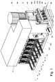
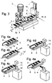
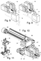
- each one of the to be fed different contact strips 1a to 1f associated contact feed stations 2a to 2f for the selective feed of a certain contact a, b, c, d, e or f in a contact gripping position see Figures 3, 4b and 4c.
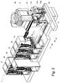
- Number of contact supply stations 2a to 2f are the latter as individually mountable and / or interchangeable units (see 2d in FIG 2) trained.
- Each of the contact supply stations 2a to 2f is as can be seen in particular from FIGS. 3 and 4a to 4e, with a band guide 3.3 'to the side Leading one forward in its longitudinal direction A. transporting contact belt 1a, 1b, 1c, 1d, 1e, respectively 1f and in openings 4 of the contact carrier strip 1a ', 1b', 1c ', 1d', 1e 'respectively. 1f 'engaging Feed means 6 for incremental feed a selected contact band 1a by a respective lateral contact distance s (Fig. 3) corresponding Distance t (Fig. 4) provided.
- the feed means 6 are in a known manner actuated by means of pneumatic cylinders 7.
- the in the crimping station 8 to be attached to a conductor 9 Contact a is by means of the individual contacts a of a contact strip 1a connecting each other Contact carrier strip 1 a 'in a displacement path 10 a contact gripping part 11 of a first contact transfer unit 12 current contact position 13a (Fig. 4c) moves. In the latter the contact to be fed to the crimping station 8 a via its associated contact carrier strip section 1a '' (see Fig.
- the contact gripping part 11 becomes unimpeded Retraction of the first contact transfer unit 12 in a the possible in front of the contact supply stations 2a to 2f located contact engagement positions 13a, 13b, 13c, 13d ... below the contact gripping part 17 of the second contact transfer unit and below the latter lowered and after passing the two the latter 17.18 back to the level of the Contact gripping positions 13a, 13b, 13c, 13d etc. raised.
- first contact transfer unit 12 To move the first contact transfer unit 12 along the displacement path 20 is one along the latter extending, in one place with the first Cable transfer unit 12 connected, endlessly rotating, Conveyor belt designed as a toothed belt 21 provided, which at its one deflecting end a correspondingly toothed deflection roller runs, and engages with this in a form-fitting manner.
- This deflection roller is driven by a stepper motor 22 connected, which to its control or the displacement distance the first contact transfer unit 12 is connected to a control unit 23, via which the respective end positions 16; 13a, 13b, 13c, 13d ... of the displacement path 20 are adjustable.
- the contact gripping part 11 of the first contact transfer unit 12 moved past this area 24 sufficiently lowered, to then before the transfer position 16 again to be raised to the level of the latter.
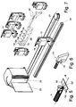
- the second contact transfer unit 18 is by means of a hydraulic or pneumatic actuating cylinder 25 along a guide 26 between two end stops slidable.
- a hydraulic or pneumatic actuating cylinder 25 along a guide 26 between two end stops slidable.
- different large contact carrier strip sections 1a '' are the two gripper parts horizontally over two sides Movable towards each other Slide parts 27 and 27 'on a crossbar 28 adjustable guided.
- the crossbar 28 is in turn over one extending in the vertical direction Support and guide part 29 in a sliding support 30 slidably guided and the compression springs 31st and 32 springs supported in the latter.
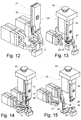
- the crimping station 8 shown in Figures 1 and 2 The device can e.g. as from Figures 12 up to 15, with a very conventional one Crimping tool 33 can be equipped.
- the crimping press is driven in the usual way by means of a drive motor 36.
- the crimping station 8 As shown in FIGS and 2 can be seen, several arranged side by side, different crimping inserts, and laterally slidable than conventional ones Quick-change tools trained crimping tools 33a, 33b, 33c ..., the latter with each a wire and an insulation stamp 36 and 37, respectively and one of the two anvil units assigned to the latter 38 provided.
- the crimping tools 33a, 33b, 33c ... are included of the anvil units 38 assigned to them, such as seen in Figure 1, in a laterally displaceable Cross slide 39 arranged, and with the latter connected drive means 40 provided to be selective a corresponding to the contact to be processed a Crimping tool 33b by moving the Cross slide 39 in its crimping position bring.
- the punch holder 41 of the individual crimping tools 33a, 33b, 33c ... are on their top, as in particular 1, each with a snap-in part 42 for laterally releasable engagement with the drive elements 43,44,36 of the Crimea press 8 when it is moved in the crimping insert position.
- FIG a crimping station 8 according to the invention, which each with an electrically operated Crimp height adjustment for the wire stamp 36 and for the insulation stamp 37 is provided, so that both Stamps completely independent of each other regarding their Crimp height can be adjusted.
- the wire stamp 36 and the insulation stamp are included 37 of each individual crimp insert analog to the embodiment shown in Figure 26, however without the crimp height adjustment elements shown there 45.46, individually on a stamp holder 47 and 48 arranged.
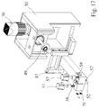
- FIG. 17 shows in FIG shown crimping station 8 with the drive motor 36 connected drive eccentric 49, which for Effecting a lifting movement in its vertical Movement direction C slidably guided in the housing 50
- Drive carriage 51 over one with this connected bear 87 acts on the latter.
- stamp holder 47 and 48 For crimp height adjustment of the two in the crimping position are located stamp holder 47 and 48 with the locking parts 42 and 42 'of the latter two can be releasably engaged by lateral displacement further latching parts 52 and 52 'are provided, which in the direction of displacement C of the drive slide 51 are arranged adjustable in the latter.
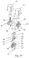
- the eccentric middle parts 53 'and 54' of the two Eccentric shafts 53 and 54 each engage in an opening 59 of a pressure piece 60 a.
- the cone-shaped further snap-in parts 52 and 52 ' are in cylindrical bores of the drive carriage 51 slidable in the vertical direction guided and each have a recess in their upper part 61 or 61 'for holding one pressure sensor each 62 or 62 'as well as a thrust washer covering these 63 or 63 'to support the assigned Pressure piece 60 or 60 '.
- the pressure sensors 62 and 62 ' are connected to an evaluation circuit, in which during the crimping process the on the two Stamp 36 and 37 registered crimp force registered and if a specified limit is exceeded or undershot An error signal and / or the device is turned off.
- latching means 65, 65 'to 72 are provided, which are arranged and / or designed in this way are that the stamp holder 47 and 48 at their side Shift from a crimping position out by lateral displacement of the cross slide 39 in the direction of arrow D, i.e. with a decoupling of the drive elements 96, 49, 51 and 52 or 52 'of the crimping press, by means of these locking means in held in their upper starting position, or at their lateral shift into the crimping insert position, i.e. when coupled to the drive elements 52, 52 'of the Crimea press, for its longitudinal displacement in be released in the vertical direction.
- each pair of stamp holders 47, 48 is one with two Locking cams 67, 68 and a guide part 69, in its longitudinal direction against the spring pressure a compression spring 70 in a non-locking position Slidable locking pin 66 is provided.
- a such shift will be in the crimping insert position of a pair of stamp holders 47, 48 with the help of one on one Cam bar 72 provided cam 71 causes which in this position is the rear of the cross slide 39 protruding end part 73 of the locking bolt 66 pushes in so far that the two Locking cams 67 and 68 out of engagement with the assigned, provided in the stamp holders 47 and 48 Arresting recesses 65 and 65 'get, and thereby which now with the further locking means 52 and 52 'of Drive carriage 51 connected stamp holder 47 and 48 to their longitudinal displacement in the vertical direction release.
- a stepper motor 74 via a bevel gear 75 an adjusting spindle 76, which in turn has a Spindle nut 77 and a tube sleeve connected to it 78 acts on an angle part 79, the the latter in turn with a fastening part 80 for Attachment to the cross slide 39 is connected.
- Stepper motor 74 is in turn with control electronics connected, which is a precise control of the shift of the various crimping tools in the Crimp insert position causes.
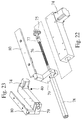
- the crimping station 8 is not electrically operable crimp height adjustment is provided the for the wire and the insulation stamp 36 and 37 serving stamp holders 47 and 48 also, as can be seen from FIGS. 24 and 26, for Fine adjustment of their crimp height each with an eccentric part 45 be provided, the eccentric pin 45 'in one extending in the vertical direction, in a wedge-shaped in the horizontal direction Wedge element 46 provided longitudinal slot 46 'extends.
- the longitudinal slot 46 ' is used for that when rotating of the eccentric pin 45 'only a shift of the Wedge element 46 in the horizontal direction, however no forced deflection of the same in vertical Direction is effected.
- Figure 25 shows the interaction of the attached to the two stamp holders 47 and 48 Wire and insulation stamps 36 and 37 with one associated anvil unit 38.
- All relevant drive and adjustment units the device are such via a control unit connected with each other that when a certain one is selected Contact type automatically the appropriate contact supply station is activated, the feed of the selected Contact and the first contact transfer unit by a feed distance assigned to each of them in the appropriate contact grasping position, the contact gripping parts of the gripper second contact transfer unit to one of the length of the to be taken contact carrier strip section position and that for the selected contact suitable crimping tools moved into the crimping insert position so that a fully automatic process all functions for fastening the selected contact done on a ladder.
Landscapes
- Engineering & Computer Science (AREA)
- Manufacturing & Machinery (AREA)
- Manufacturing Of Electrical Connectors (AREA)
Applications Claiming Priority (3)
| Application Number | Priority Date | Filing Date | Title |
|---|---|---|---|
| CH158597A CH693370A5 (de) | 1997-06-30 | 1997-06-30 | Verfahren und Vorichtung zur Ueberführung von Kontakten zu einer Kontaktverarbeitungsstation. |
| CH1585/97 | 1997-06-30 | ||
| CH158597 | 1997-06-30 |
Publications (2)
| Publication Number | Publication Date |
|---|---|
| EP0889560A1 true EP0889560A1 (fr) | 1999-01-07 |
| EP0889560B1 EP0889560B1 (fr) | 2000-05-03 |
Family
ID=4213858
Family Applications (1)
| Application Number | Title | Priority Date | Filing Date |
|---|---|---|---|
| EP19970810726 Expired - Lifetime EP0889560B1 (fr) | 1997-06-30 | 1997-10-01 | Méthode et unité pour passer des contacts à un appareil de traitement de contacts |
Country Status (3)
| Country | Link |
|---|---|
| EP (1) | EP0889560B1 (fr) |
| CH (1) | CH693370A5 (fr) |
| DE (1) | DE59701585D1 (fr) |
Cited By (7)
| Publication number | Priority date | Publication date | Assignee | Title |
|---|---|---|---|---|
| EP1764883A1 (fr) * | 2005-09-19 | 2007-03-21 | komax Holding AG | Système de traitement de câble au moyen d'au moins deux outils |
| EP2592703A3 (fr) * | 2011-11-14 | 2014-01-15 | Schäfer Werkzeug- und Sondermaschinenbau GmbH | Dispositif d'alimentation variable pour un agrégat de sertissage |
| WO2016128331A1 (fr) * | 2015-02-12 | 2016-08-18 | Zoller & Fröhlich GmbH | Machine de sertissage |
| CN108428598A (zh) * | 2018-05-21 | 2018-08-21 | 杭州杰涵机械科技有限公司 | 一种塑壳断路器动触头自动铆接装置及其操作方法 |
| EP4047757A1 (fr) * | 2021-02-17 | 2022-08-24 | MD Elektronik GmbH | Dispositif et procédé d'usinage des contacts |
| CN115708280A (zh) * | 2021-08-19 | 2023-02-21 | 迈恩德电子有限公司 | 用于触点与导线的分离和接合的方法和工具 |
| DE102023104906A1 (de) | 2023-02-28 | 2024-08-29 | Harting Electric Stiftung & Co. Kg | Zuführeinrichtung für einen Crimpautomaten, Crimpautomat, Gurtband und Gurtsystem, Zuführsystem, Verfahren zum Betrieb des Crimpautomaten, Hybridsteckverbinder und Bestückungsverfahren für denselben |
Citations (5)
| Publication number | Priority date | Publication date | Assignee | Title |
|---|---|---|---|---|
| US4982830A (en) * | 1989-10-18 | 1991-01-08 | Amp Incorporated | Product feeding apparatus |
| EP0427668A1 (fr) * | 1989-11-07 | 1991-05-15 | Ulrich Blecher | Machine à sertir |
| EP0622873A2 (fr) * | 1993-04-26 | 1994-11-02 | The Whitaker Corporation | Mécanisme d'entraînement pour le poinçon |
| EP0711010A2 (fr) * | 1994-11-07 | 1996-05-08 | SUMITOMO WIRING SYSTEMS, Ltd. | Système d'alimentation de banes et outil de sertissage employé pour celui-ci |
| EP0730326A2 (fr) * | 1995-03-02 | 1996-09-04 | The Whitaker Corporation | Méthode pour évaluer une connexion électrique sertie |
-
1997
- 1997-06-30 CH CH158597A patent/CH693370A5/de not_active IP Right Cessation
- 1997-10-01 DE DE59701585T patent/DE59701585D1/de not_active Expired - Lifetime
- 1997-10-01 EP EP19970810726 patent/EP0889560B1/fr not_active Expired - Lifetime
Patent Citations (5)
| Publication number | Priority date | Publication date | Assignee | Title |
|---|---|---|---|---|
| US4982830A (en) * | 1989-10-18 | 1991-01-08 | Amp Incorporated | Product feeding apparatus |
| EP0427668A1 (fr) * | 1989-11-07 | 1991-05-15 | Ulrich Blecher | Machine à sertir |
| EP0622873A2 (fr) * | 1993-04-26 | 1994-11-02 | The Whitaker Corporation | Mécanisme d'entraînement pour le poinçon |
| EP0711010A2 (fr) * | 1994-11-07 | 1996-05-08 | SUMITOMO WIRING SYSTEMS, Ltd. | Système d'alimentation de banes et outil de sertissage employé pour celui-ci |
| EP0730326A2 (fr) * | 1995-03-02 | 1996-09-04 | The Whitaker Corporation | Méthode pour évaluer une connexion électrique sertie |
Cited By (11)
| Publication number | Priority date | Publication date | Assignee | Title |
|---|---|---|---|---|
| EP1764883A1 (fr) * | 2005-09-19 | 2007-03-21 | komax Holding AG | Système de traitement de câble au moyen d'au moins deux outils |
| US7340812B2 (en) | 2005-09-19 | 2008-03-11 | Komax Holding Ag | System for processing a cable using at least two tools |
| EP2592703A3 (fr) * | 2011-11-14 | 2014-01-15 | Schäfer Werkzeug- und Sondermaschinenbau GmbH | Dispositif d'alimentation variable pour un agrégat de sertissage |
| WO2016128331A1 (fr) * | 2015-02-12 | 2016-08-18 | Zoller & Fröhlich GmbH | Machine de sertissage |
| US11121516B2 (en) | 2015-02-12 | 2021-09-14 | Zoller & Fröhlich GmbH | Crimping machine |
| CN108428598A (zh) * | 2018-05-21 | 2018-08-21 | 杭州杰涵机械科技有限公司 | 一种塑壳断路器动触头自动铆接装置及其操作方法 |
| CN108428598B (zh) * | 2018-05-21 | 2023-09-12 | 杭州杰涵机械科技有限公司 | 一种塑壳断路器动触头自动铆接装置及其操作方法 |
| EP4047757A1 (fr) * | 2021-02-17 | 2022-08-24 | MD Elektronik GmbH | Dispositif et procédé d'usinage des contacts |
| CN115708280A (zh) * | 2021-08-19 | 2023-02-21 | 迈恩德电子有限公司 | 用于触点与导线的分离和接合的方法和工具 |
| DE102023104906A1 (de) | 2023-02-28 | 2024-08-29 | Harting Electric Stiftung & Co. Kg | Zuführeinrichtung für einen Crimpautomaten, Crimpautomat, Gurtband und Gurtsystem, Zuführsystem, Verfahren zum Betrieb des Crimpautomaten, Hybridsteckverbinder und Bestückungsverfahren für denselben |
| WO2024179637A1 (fr) | 2023-02-28 | 2024-09-06 | Harting Electric Stiftung & Co. Kg | Dispositif d'alimentation pour une machine de sertissage, machine de sertissage, bande et système de bande, système d'alimentation, procédé de fonctionnement de la machine de sertissage, connecteur hybride et son procédé d'assemblage |
Also Published As
| Publication number | Publication date |
|---|---|
| DE59701585D1 (de) | 2000-06-08 |
| EP0889560B1 (fr) | 2000-05-03 |
| CH693370A5 (de) | 2003-06-30 |
Similar Documents
| Publication | Publication Date | Title |
|---|---|---|
| EP0889561B1 (fr) | Machine à sertir et méthode d'utilisation | |
| DE2744235C2 (fr) | ||
| DE3340744C2 (fr) | ||
| DE2660368C2 (de) | Bestückungsmaschine zum Einsetzen der Zuleitungen von elektronischen Bauelementen vom Parallelleitungstyp in dafür vorgesehene Öffnungen in gedruckten Schaltungen | |
| EP0429941B1 (fr) | Dispositif pour couper des feuilles empilées | |
| DE4008515C2 (fr) | ||
| DE69009368T2 (de) | Vorrichtung und Verfahren zur Drahtbearbeitung. | |
| DE3883922T2 (de) | Düsen-Wechselvorrichtung für Extruder. | |
| EP0476718A1 (fr) | Dispositif pour piquer des produits d'imprimerie à plusieurs parties | |
| DE8124805U1 (de) | Einrichtung für das selbständige Zuführen und Abholen von Paletten eines Palettenmagazins in den bzw. aus dem Arbeitsraum einer Werkzeugmaschine | |
| DE2818018A1 (de) | Verfahren und vorrichtung zum selbstaendigen werkzeugwechsel bei waelzfraesmaschinen | |
| EP0212077A2 (fr) | Dispositif de guidage de barres | |
| DE60010672T2 (de) | Vorrichtung und Verfahren zum Bedrucken von Drähten | |
| EP0889560B1 (fr) | Méthode et unité pour passer des contacts à un appareil de traitement de contacts | |
| DE102008051525A1 (de) | Vorrichtung und Verfahren zum automatischen Bestücken von elektrischen Bauelementen mit Kontaktelementen | |
| DE69520671T2 (de) | Kabelverarbeitungsvorrichtung | |
| DE19627746C2 (de) | Tiefdruck-Graviersystem | |
| DE2849751C2 (de) | Vorrichtung zum Vereinzeln von ein loses Bündel bildenden abgelängten Drähten, insbesondere zwechs Drahtzufuhr zu einer Verarbeitungsmaschine | |
| EP1351349A1 (fr) | Presse de sertissage pour la réalisation de connexions de sertissage | |
| EP0328716B1 (fr) | Soudeuse | |
| DE2950460A1 (de) | Vorrichtung zum einsetzen von anschlussstiften | |
| DE3416678A1 (de) | Automatische biegevorrichtung fuer betonstahl | |
| WO1985004290A1 (fr) | Machine pour munir par sertissage les extremites des conducteurs d'un cable, de douilles d'expremite ou d'autres elements de connexion | |
| DE1935451C2 (de) | Vorrichtung zum Vereinzeln und Einführen von bolzenförmigen Rohlingen an einer Bearbeitungsmaschine | |
| EP0708508A1 (fr) | Procédé et dispositif pour équiper des boîtiers de connecteurs |
Legal Events
| Date | Code | Title | Description |
|---|---|---|---|
| PUAI | Public reference made under article 153(3) epc to a published international application that has entered the european phase |
Free format text: ORIGINAL CODE: 0009012 |
|
| AK | Designated contracting states |
Kind code of ref document: A1 Designated state(s): DE FR GB IT |
|
| 17P | Request for examination filed |
Effective date: 19990305 |
|
| AKX | Designation fees paid |
Free format text: DE FR GB IT |
|
| GRAG | Despatch of communication of intention to grant |
Free format text: ORIGINAL CODE: EPIDOS AGRA |
|
| GRAG | Despatch of communication of intention to grant |
Free format text: ORIGINAL CODE: EPIDOS AGRA |
|
| GRAH | Despatch of communication of intention to grant a patent |
Free format text: ORIGINAL CODE: EPIDOS IGRA |
|
| 17Q | First examination report despatched |
Effective date: 19991025 |
|
| GRAH | Despatch of communication of intention to grant a patent |
Free format text: ORIGINAL CODE: EPIDOS IGRA |
|
| GRAA | (expected) grant |
Free format text: ORIGINAL CODE: 0009210 |
|
| AK | Designated contracting states |
Kind code of ref document: B1 Designated state(s): DE FR GB IT |
|
| PG25 | Lapsed in a contracting state [announced via postgrant information from national office to epo] |
Ref country code: IT Free format text: LAPSE BECAUSE OF FAILURE TO SUBMIT A TRANSLATION OF THE DESCRIPTION OR TO PAY THE FEE WITHIN THE PRE;WARNING: LAPSES OF ITALIAN PATENTS WITH EFFECTIVE DATE BEFORE 2007 MAY HAVE OCCURRED AT ANY TIME BEFORE 2007. THE CORRECT EFFECTIVE DATE MAY BE DIFFERENT FROM THE ONE RECORDED.SCRIBED TIME-LIMIT Effective date: 20000503 |
|
| REF | Corresponds to: |
Ref document number: 59701585 Country of ref document: DE Date of ref document: 20000608 |
|
| EN | Fr: translation not filed | ||
| GBV | Gb: ep patent (uk) treated as always having been void in accordance with gb section 77(7)/1977 [no translation filed] |
Effective date: 20000503 |
|
| PLBE | No opposition filed within time limit |
Free format text: ORIGINAL CODE: 0009261 |
|
| STAA | Information on the status of an ep patent application or granted ep patent |
Free format text: STATUS: NO OPPOSITION FILED WITHIN TIME LIMIT |
|
| 26N | No opposition filed | ||
| REG | Reference to a national code |
Ref country code: GB Ref legal event code: 710B Free format text: A REQUEST HAS BEEN FILED TO EXTEND THE PERIOD FOR FILING A TRANSLATION OF THE SPECIFICATION. |
|
| REG | Reference to a national code |
Ref country code: GB Ref legal event code: 710B Free format text: APPLICATION FOR EXTENSION OF THE PERIOD(S) FILED ON 08 MAY 2001. |
|
| GBT | Gb: translation of ep patent filed (gb section 77(6)(a)/1977) |
Effective date: 20010921 |
|
| REG | Reference to a national code |
Ref country code: GB Ref legal event code: 711T Ref country code: GB Ref legal event code: 710B Free format text: THE PATENT IS NOW REINSTATED WITH A GRANT DATE OF 03.05.2000. |
|
| REG | Reference to a national code |
Ref country code: FR Ref legal event code: RN |
|
| REG | Reference to a national code |
Ref country code: FR Ref legal event code: FC |
|
| ET | Fr: translation filed | ||
| REG | Reference to a national code |
Ref country code: GB Ref legal event code: IF02 |
|
| PGFP | Annual fee paid to national office [announced via postgrant information from national office to epo] |
Ref country code: GB Payment date: 20081021 Year of fee payment: 12 |
|
| PG25 | Lapsed in a contracting state [announced via postgrant information from national office to epo] |
Ref country code: GB Free format text: LAPSE BECAUSE OF NON-PAYMENT OF DUE FEES Effective date: 20091001 |
|
| PGFP | Annual fee paid to national office [announced via postgrant information from national office to epo] |
Ref country code: FR Payment date: 20101104 Year of fee payment: 14 |
|
| REG | Reference to a national code |
Ref country code: FR Ref legal event code: ST Effective date: 20120629 |
|
| PG25 | Lapsed in a contracting state [announced via postgrant information from national office to epo] |
Ref country code: FR Free format text: LAPSE BECAUSE OF NON-PAYMENT OF DUE FEES Effective date: 20111102 |
|
| PGFP | Annual fee paid to national office [announced via postgrant information from national office to epo] |
Ref country code: DE Payment date: 20131021 Year of fee payment: 17 |
|
| REG | Reference to a national code |
Ref country code: DE Ref legal event code: R119 Ref document number: 59701585 Country of ref document: DE |
|
| PG25 | Lapsed in a contracting state [announced via postgrant information from national office to epo] |
Ref country code: DE Free format text: LAPSE BECAUSE OF NON-PAYMENT OF DUE FEES Effective date: 20150501 |