EP4047757A1 - Dispositif et procédé d'usinage des contacts - Google Patents
Dispositif et procédé d'usinage des contacts Download PDFInfo
- Publication number
- EP4047757A1 EP4047757A1 EP22152495.2A EP22152495A EP4047757A1 EP 4047757 A1 EP4047757 A1 EP 4047757A1 EP 22152495 A EP22152495 A EP 22152495A EP 4047757 A1 EP4047757 A1 EP 4047757A1
- Authority
- EP
- European Patent Office
- Prior art keywords
- carrier strip
- clamping device
- clamping
- tool
- contacts
- Prior art date
- Legal status (The legal status is an assumption and is not a legal conclusion. Google has not performed a legal analysis and makes no representation as to the accuracy of the status listed.)
- Granted
Links
Images

Classifications
-
- H—ELECTRICITY
- H01—ELECTRIC ELEMENTS
- H01R—ELECTRICALLY-CONDUCTIVE CONNECTIONS; STRUCTURAL ASSOCIATIONS OF A PLURALITY OF MUTUALLY-INSULATED ELECTRICAL CONNECTING ELEMENTS; COUPLING DEVICES; CURRENT COLLECTORS
- H01R43/00—Apparatus or processes specially adapted for manufacturing, assembling, maintaining, or repairing of line connectors or current collectors or for joining electric conductors
- H01R43/04—Apparatus or processes specially adapted for manufacturing, assembling, maintaining, or repairing of line connectors or current collectors or for joining electric conductors for forming connections by deformation, e.g. crimping tool
- H01R43/048—Crimping apparatus or processes
-
- H—ELECTRICITY
- H01—ELECTRIC ELEMENTS
- H01R—ELECTRICALLY-CONDUCTIVE CONNECTIONS; STRUCTURAL ASSOCIATIONS OF A PLURALITY OF MUTUALLY-INSULATED ELECTRICAL CONNECTING ELEMENTS; COUPLING DEVICES; CURRENT COLLECTORS
- H01R43/00—Apparatus or processes specially adapted for manufacturing, assembling, maintaining, or repairing of line connectors or current collectors or for joining electric conductors
- H01R43/04—Apparatus or processes specially adapted for manufacturing, assembling, maintaining, or repairing of line connectors or current collectors or for joining electric conductors for forming connections by deformation, e.g. crimping tool
- H01R43/048—Crimping apparatus or processes
- H01R43/055—Crimping apparatus or processes with contact member feeding mechanism
Definitions
- the invention relates to a device and a method for processing contacts, in particular for crimping contacts onto conductors.
- contacts are permanently and firmly connected to the conductors of a cable.
- One connection technique involves crimping a contact onto a conductor. During crimping, a contact is arranged on at least one conductor of a cable, and then both parts are pressed or crimped together by mechanical pressure.
- a large number of contacts are preferably arranged, i.e. attached, to a carrier strip. The contacts are arranged at a distance from one another along the carrier strip, and by advancing the carrier strip to a tool, in particular a crimping tool, the contacts can be fed to the tool one after the other.
- Crimping requires that each contact be consistently and precisely positioned within the crimping tool, particularly over an anvil, as predetermined, in order to achieve consistent results.
- pilot holes formed along the carrier strip can be used. Fixing means in a guide track or in the tool can engage in at least one pilot hole and, by the predetermined position of the fixing means, locating the carrier strip and the contacts in a predetermined position.
- the arrangement of the contacts using the pilot holes can be subject to errors and expensive.
- the pamphlet EP1381124A1 relates to a crimping press for producing a crimped connection.
- the crimping press has guide parts that can be adjusted as a whole in the direction of the cable, so that the position of a crimp contact on a lower tool or on an anvil can be precisely determined.
- a device for processing contacts the contacts being arranged on a carrier strip, having a tool for processing the contacts, a guideway for feeding the at least one carrier strip in a feed direction to the tool, and a clamping device , which is arranged in the feed direction after the tool, for clamping the at least one carrier strip perpendicular to the feed direction.
- a carrier strip is aligned exactly in the feed direction V in the guide track.
- the guideway ensures that the carrier strip can be arranged with a precise fit in the tool. When the tool is used to process contacts, this precise arrangement is necessary for consistently precise processing. A deviation of the carrier strip from the feed direction on a side downstream of the tool in the feed direction can have a negative effect on the precise arrangement.
- the clamping device which is arranged after the tool in the direction of feed, ensures that the exact alignment of the carrier strip is also maintained after the tool. A deviation from the exact alignment, for example due to a curvature (Saber curvature) of the carrier strip, after the tool, is prevented by the clamping device.
- the device, and in particular the clamping device can be used for various tools that provide for the processing of banded goods.
- the clamping device is movable between an open and a closed position.
- the clamping device is an active system that only clamps when it is necessary or determined.
- the clamp clamps after each feed i.e. moving on from one contact to the next. This avoids continuous stress on the materials, in particular on the carrier strip.
- the point in time, the duration and the strength of a clamp can be predetermined. In this way, the clamping device can be optimally adapted to a processing method and/or a carrier strip.
- the clamping device is preferably in a closed position while a contact can be processed by the tool. Accurate and solid placement of a contact in the tool is important, especially during a machining process. Due to the clamping, especially during this period of time, consistently precise results can be achieved.
- the clamping device comprises a first clamping device, wherein a clamping force applied by the first clamping device, transverse to the feed direction and in a carrier strip contact plane, can be applied to the carrier strip, or a second clamping device, wherein a clamping force applied by the second clamping device, transverse to the feed direction and transverse to the carrier strip contact plane, is applicable to the carrier strip.
- the clamping force acts on the carrier strip in the carrier strip contact plane, then the clamping force is transmitted over a very small contact area between the clamp and the carrier strip.
- a high clamping pressure which clamps the carrier strip, can be generated with a low clamping force. If the clamping force acts transversely, and in particular perpendicularly, to the carrier strip contact plane, the clamping force is transmitted over a relatively large contact area between the clamping device and the carrier strip. The resulting clamping pressure is less and the material is less stressed.
- the first and/or second clamping device preferably comprises a pneumatic or hydraulic system.
- a pneumatic or hydraulic system With the help of a pneumatic or hydraulic system, the applied clamping forces can be precisely adjusted. An adaptation to different process conditions and/or carrier strips is thus possible. Both small and large forces can also be generated with the systems mentioned. For example, depending on the material of the carrier strip, i.e. in adaptation to its curvature, a more or less strong clamping force can be applied. In addition, the systems react very quickly, so that a change from the open to the closed position and vice versa can be carried out quickly.
- the first and/or second clamping device comprises at least one stop and a plunger, wherein only the carrier strip can be clamped between the plunger and the stop in the closed position of the first and/or second clamping device.
- the plunger is preferably moved toward and away from the stop in a plunger guide. As a result, a directed movement and power transmission can take place.
- the stop and plunger form aligned surfaces that accurately align the carrier strip in the feed direction in the closed position.
- the clamping force only acts on the carrier strip. There are preferably no longer any contacts on the carrier strip in the feed direction after the tool. In individual cases, however, contacts can still be attached to the carrier strip. Since the plunger acts directly on the carrier strip, regardless of whether there are still contacts on the carrier strip or not, the clamping works with or without contacts on the carrier strip in any case.
- the device preferably also has an angle element which is attached to the clamping device, the angle element being connected to the guide track by means of attachment means.
- the angle element is preferably a rigid component that is firmly connected to the guideway.
- a method for processing contacts wherein the contacts are arranged on a carrier strip, preferably with a device for processing contacts, the method comprises the steps of: feeding the carrier strip in a feeding direction to a tool and a clamping device, which is arranged downstream of the tool in the feeding direction, by means of a guideway, clamping the carrier strip perpendicularly to the feeding direction by means of the clamping device, and processing a contact of the carrier strip by the Tool.
- the clamping step is preferably performed prior to machining a contact.
- the contact to be machined is first arranged in its predetermined position in the tool, for example over an anvil.
- the contact is also fixed in its predetermined position, so that the position of the contact does not change. Only after the contact has been arranged in its predetermined position does the processing of the contact take place. This ensures consistent and precise processing of the contacts.
- the clamping includes moving a plunger of the clamping device from an open to a closed position.
- a plunger of the clamping device By actively clamping and releasing, it can be predetermined at which points in time or at which points the carrier strip is clamped.
- the clamping can be optimally adapted to the processing and the carrier strip.
- the clamping of the carrier strip is preferably released, so that the carrier strip can be moved in the feed direction.
- the clamping is therefore only temporary. This puts less stress on the material. The friction between the parts that occurs with permanent clamping or pressing is avoided. After clamping, unhindered movement of the carrier strip is possible.
- a multiplicity of contacts 5 are preferably arranged on a carrier strip 3, ie fastened to it.
- the carrier strip 3 facilitates the handling of the contacts 5 in particular.
- a pilot hole 7 is preferably formed on the carrier strip 3 between two adjacent contacts 5 .
- the carrier strip 3 can be moved in the feed direction V via a pilot hole 7 with the aid of a feed 20 which engages in the pilot hole 7 with a feed finger 22 .
- One or more support strips 3 can be arranged in a supply 10 .
- a supply 10 can be, for example, a supply roll.
- a continuous supply of contacts 5 or carrier strips 3 is desirable. The provision can be realized by one or more supplies 10.
- contacts 5 or carrier strips 3 can also be provided directly from a process module that is upstream of the machining process with tool 40 .
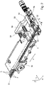
- a carrier strip 3 is fed to a tool 40 along a guide track 30 .
- the movement of the carrier strip 3 in a feed direction V towards the tool 40 is preferably implemented by a feed 20 .
- To move the carrier strip 3 grips in particular a feed finger 22 of the feed 20 into a pilot hole 7 of the carrier strip 3 and pushes the carrier strip 3 in the feed direction V.
- the tool 40 is set up to machine a contact 5 that is located in a machining area 44 of the tool 40 .
- the tool 40 is preferably mounted on a base plate 60 .
- a tool 40 can crimp or press a contact 5 or deform it in some other way.
- a contact 5 is preferably processed by wearing parts 42 on the tool 40.
- a contact 5 is separated from the carrier strip 3 at the same time as the crimping.
- several tools 40 can be arranged one behind the other in the feed direction V.
- the carrier strip 3 is aligned exactly in the feed direction V within the tool 40 or the processing area 44 of the tool 40 coming from the supply 10 through the guide track 30 . Exact alignment is important for consistent and predetermined processing of the contacts 5. The further away a contact 5 or a section of the carrier strip 3 is from the guideway 30 or the tool 40, the greater the deviations of the carrier strip 3 from the exact alignment in the feed direction V occur.
- material properties of the carrier strip 3 can cause the carrier strip 3 to curve, a so-called saber curvature. With this curvature, the carrier strip 3 curves in its carrier strip contact plane X-Y in a second direction Y away from an original straight line in the feed direction V.
- the carrier strip 3, and thus also the contacts 5 fastened to the carrier strip 3, are no longer exactly aligned in the feed direction V.
- the curvature can lead to problems in subsequent processing steps of the carrier strip 3.
- the curvature can also lead to an unwanted deviation of the carrier strip 3 from the exact alignment in the feed direction V within the tool 40, quasi retroactively counter to the feed direction V. This would lead to problems when processing a contact 5 in the tool 40.
- At least one first clamping device 50 is arranged in the feed direction V after the tool 40, which is set up to clamp the carrier strip 3 perpendicular to the feed direction V jam.
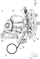
- FIG. 2 shows a detailed view of the guide track 30 and an embodiment of the first clamping device 50.
- a carrier strip 3 with contacts 5 and pilot holes 7 is arranged along the guide track 30 and the first clamping device 50.
- FIG. In 2 For the sake of clarity, no tool 40 is shown between the guide track 30 and the first clamping device 50 .
- the carrier strip 3 is fed from the guide track 30 in the feed direction V of the first clamping device 50 .
- the first clamping device 50 shown is in an open or open position, i.e. a plunger 52 of the first clamping device 50 protrudes by a length L1 from a pneumatic cylinder 51 of the first clamping device 50 in a second direction Y in the direction of the carrier strip 3.
- the pneumatic cylinder 51 can also be a hydraulic cylinder or the like.
- the length L1 can be monitored by a magnetic field sensor 53.
- the pneumatic cylinder 51 is connected to a pneumatic system via pneumatic connections 55 .
- a stop 54 is arranged at a distance from the pressure stamp 52 in the second direction Y, which is the direction of movement of the pressure stamp 52 .
- the stop 54 has at least one stop surface which extends in the feed direction V and against which a carrier strip 3, which is exactly aligned in the feed direction V, can rest in parallel.
- the pressure pad 52 and its direction of movement is preferably aligned transversely, in particular perpendicularly, to the carrier strip 3 .
- the pressure plunger 52 can preferably be moved and pressed in the direction of the stop 54 by a floatingly mounted pneumatic cylinder 51 .
- the carrier strip 3 has a width B in the carrier strip contact plane XY, in which the carrier strip 3 with contacts 5 lies.
- the width B is measured from a side of the carrier strip 3 facing away from the contact to an opposite tip of a contact 5.
- a tip of the plunger 52 facing the stop 54 is at least a distance A from the carrier strip 3 with contacts 5 spaced. Due to the distance A, the carrier strip 3 with contacts 5 can be moved in the feed direction V without being hindered by the plunger 52 . This is particularly advantageous in the event that a contact 5 has not been separated from the carrier strip 3.
- the carrier strip 3 is moved in the feed direction V. At least during this movement, the first clamping device 50 is in the open position.
- the first clamping device 50 in 2 connected to the guide track 30 via an angle element 56 .
- the first clamping device 50 is fastened to the guide track 30 via the angle element 56 by means of fastening means 58, for example dowel pins. Due to the connection or attachment, a displacement of the guideway 30 automatically leads to a corresponding displacement of the first clamping device 50. An additional adjustment of the first clamping device 50 to the guideway 30 is not necessary.
- the first clamping device 50 is in a closed position. In the closed position, the plunger 52 protrudes from the pneumatic cylinder 51 by a length L2. The length L2 is greater than the length L1. In doing so, the plunger 52 clamps the carrier strip 3 between itself and a stop face on the stop 54 . By clamping the carrier strip 3 is aligned exactly in the feed direction V on the stop surface. Furthermore, the carrier strip 3 is prevented from moving in the feed direction V.
- the pressure plunger 52 is arranged in the closed position between two adjacent contacts 5 and acts with its clamping force only on the carrier strip 3. An unwanted bending of a contact 5 by clamping is avoided in this way. The arrangement of the pressure plunger 52 between two adjacent contacts 5 also prevents a movement of the carrier strip 3 along, i.e. in both directions, the feed direction V in a form-fitting manner.
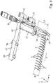
- FIG. 4 shows a second embodiment of a device 100 for processing a contact 5.
- a multiplicity of contacts 5 are fastened to a carrier strip 3.
- FIG. The contacts 5 or carrier strips 3 can be provided in a store 110 .
- a carrier strip 3 with contacts 5 can also be provided by an upstream production or processing module.
- a carrier strip 3 is fed to a tool 140 via a guide track 130 .
- the tool 140 is set up for processing a contact 5, in particular the tool 140 is a crimping tool.
- the contact 5 is fed to a machining area 144 within the tool 140.
- a contact 5 is then processed by wearing parts 142, for example a crimper.
- a cable 9 with at least one conductor is fed to the processing area 144 of the tool 140 .
- the cable 9 is fed, for example, in a direction transverse to the feed direction V.
- a Contact 5 is arranged on at least one conductor of the cable 9, and by actuating a crimper, the contact 5 is crimped onto the at least one conductor.
- a second clamping device 150 is arranged after the tool 140 in the feed direction V.
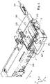
- figure 5 shows a guideway 130 and the second clamping device 150 in more detail.
- the carrier strip 3 rests on a housing 151 of the second clamping device 150 .
- a plunger 152 is also arranged on the housing 151 .
- the housing 151 forms a stop 154 in the area of the plunger 152 (see Fig. Figures 6a and 6b ).
- the pressure plunger 152 is set up to clamp a carrier strip 3 between itself and the stop 154 .
- the second clamping device 150 is also preferably connected to or attached to the guide track 130 via an angle element 156 .
- the position of the second clamping device 150 relative to the position of the guideway 130 is predetermined. If the position of the guide track 130 is changed, for example as an adjustment to different contact, carrier strips or conductor sizes, the position of the second clamping device 150 is also automatically adjusted accordingly via the angle element 156 . A separate adjustment of the guide track 130 and the second clamping device 150 is not necessary, which makes the operation of the device 100 easier.
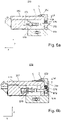
- Figure 6a shows the second clamping device 150 in a closed position, in which a carrier strip 3 is clamped.
- Figure 6b shows the second clamping device 150 in an open position in which the clamping is released or a carrier strip 3 is not clamped.
- the plunger 152 of the second clamping device 150 is preferably an L-shaped component.
- a first side of the plunger 152 is arranged opposite the stop 154 on the housing 151 .
- a second side of the plunger 152 is arranged transversely, in particular perpendicularly, to the stop 154 .
- the pressure stamp 152 extends over a pressure stamp width B2 along the feed direction V, and a carrier strip 3 can be aligned exactly in the feed direction V parallel to the second side.
- a flat clamping has the advantage that a load is distributed over a surface. In order to achieve the same clamping pressure as with a punctiform clamping, however, a higher clamping force is required for the surface clamping. Conversely, a higher clamping force can be more gentle on the material when clamping over a large area.
- a carrier strip 3 is positively fixed in two directions Y and Z by the pressure stamp 152.
- the applied clamping force fixes the carrier stiffener 3 in a non-positive manner in the feed direction V or a first direction X.
- the plunger 152 is preferably biased into the open position by a biasing element 176 (see Fig. Figure 6b ).
- a biasing element 176 may be a spring.
- the biasing member 176 is preferably connected to a bolt 174 . If the plunger 152 is to be moved from the open to the closed position, a displacement 171 can increase within the second clamping device 150 and a distance D1 between a piston 170 and an end wall of the displacement 171 can increase to a distance D2.
- the enlargement can be generated by air or liquid pressure. Any change, ie enlargement or reduction, can be monitored by a connected magnetic field sensor 153.
- the pneumatic or hydraulic system is connected to a corresponding pneumatic or hydraulic system via connections 155 .
- the piston 170 moves in the direction of the prestressing element 176.
- the piston 170 pushes itself between the prestressing element 176 and the bolt 174 with a bevel 172 or a link plunger.
- the bolt 174 becomes parallel to the second side of the pressure plunger 152 moves and pulls the biasing element 176 together with the plunger 152, so that the plunger 152 moves with its first side in the direction of the stop 154.
- a distance L4 between the first side of the plunger 152 and the stop 154 is gradually reduced, in particular linearly, by the bevel 172 until the distance L4 finally corresponds to the distance L3, which is equal to zero, in the closed position.
- the clamping force works also only on the carrier strip 3 and not on a contact 5, so that no damage to the contacts 5 can occur when clamping.
Landscapes
- Engineering & Computer Science (AREA)
- Manufacturing & Machinery (AREA)
- Manufacturing Of Electrical Connectors (AREA)
- Folding Of Thin Sheet-Like Materials, Special Discharging Devices, And Others (AREA)
Applications Claiming Priority (1)
| Application Number | Priority Date | Filing Date | Title |
|---|---|---|---|
| DE102021103674.7A DE102021103674A1 (de) | 2021-02-17 | 2021-02-17 | Vorrichtung und Verfahren zum Bearbeiten von Kontakten |
Publications (2)
| Publication Number | Publication Date |
|---|---|
| EP4047757A1 true EP4047757A1 (fr) | 2022-08-24 |
| EP4047757B1 EP4047757B1 (fr) | 2024-07-17 |
Family
ID=79831349
Family Applications (1)
| Application Number | Title | Priority Date | Filing Date |
|---|---|---|---|
| EP22152495.2A Active EP4047757B1 (fr) | 2021-02-17 | 2022-01-20 | Dispositif et procédé d'usinage des contacts |
Country Status (4)
| Country | Link |
|---|---|
| EP (1) | EP4047757B1 (fr) |
| CN (1) | CN114944580A (fr) |
| DE (1) | DE102021103674A1 (fr) |
| MX (1) | MX2022001713A (fr) |
Citations (3)
| Publication number | Priority date | Publication date | Assignee | Title |
|---|---|---|---|---|
| EP0889560A1 (fr) * | 1997-06-30 | 1999-01-07 | komax Holding AG | Méthode et unité pour passer des contacts à un appareil de traitement de contacts |
| EP1381124A1 (fr) | 2002-07-10 | 2004-01-14 | komax Holding AG | Presse de sertissage avec aménagement de contact |
| US20180131152A1 (en) * | 2016-11-08 | 2018-05-10 | Odyssey Tool, L.L.C. | Wire guide for electrical terminal applicator |
Family Cites Families (1)
| Publication number | Priority date | Publication date | Assignee | Title |
|---|---|---|---|---|
| JPH07161447A (ja) * | 1993-12-07 | 1995-06-23 | Sumitomo Wiring Syst Ltd | 自動閉端子加工機の閉端子供給機における閉端子搬送装置 |
-
2021
- 2021-02-17 DE DE102021103674.7A patent/DE102021103674A1/de not_active Ceased
-
2022
- 2022-01-10 CN CN202210021856.1A patent/CN114944580A/zh active Pending
- 2022-01-20 EP EP22152495.2A patent/EP4047757B1/fr active Active
- 2022-02-08 MX MX2022001713A patent/MX2022001713A/es unknown
Patent Citations (3)
| Publication number | Priority date | Publication date | Assignee | Title |
|---|---|---|---|---|
| EP0889560A1 (fr) * | 1997-06-30 | 1999-01-07 | komax Holding AG | Méthode et unité pour passer des contacts à un appareil de traitement de contacts |
| EP1381124A1 (fr) | 2002-07-10 | 2004-01-14 | komax Holding AG | Presse de sertissage avec aménagement de contact |
| US20180131152A1 (en) * | 2016-11-08 | 2018-05-10 | Odyssey Tool, L.L.C. | Wire guide for electrical terminal applicator |
Also Published As
| Publication number | Publication date |
|---|---|
| DE102021103674A1 (de) | 2022-08-18 |
| CN114944580A (zh) | 2022-08-26 |
| EP4047757B1 (fr) | 2024-07-17 |
| MX2022001713A (es) | 2022-08-18 |
Similar Documents
| Publication | Publication Date | Title |
|---|---|---|
| EP2043795B1 (fr) | Dispositif de butée pour presse à cintrer | |
| DE69317303T3 (de) | Selbststanzende nieten | |
| DE102008010383B4 (de) | Stanzwerkzeug, insbesondere zur Ablängung und Endenbearbeitung von Flachstabmaterial für Fensterbeschläge | |
| EP0284902A2 (fr) | Procédé et dispositif pour joindre des tôles minces mises les unes sur les autres | |
| EP3505270B1 (fr) | Unité de frappe pour un dispositif de poinçonnage, dispositif de poinçonnage et procédé de fabrication d'un tel dispositif de poinçonnage | |
| WO2019120613A1 (fr) | Dispositif de serrage d'outil pour une machine-outil et machine-outil | |
| EP3825029B1 (fr) | Drageoir | |
| DE2625915B2 (de) | Verfahren zur Herstellung von elektrischen Kontakten | |
| EP3793816B1 (fr) | Entraînement de cale à dispositif de guidage réglable | |
| AT520364A1 (de) | Fertigungsanlage zum Herstellen eines Wicklungsstabes für einen Elektromotor, sowie Verfahren zum Herstellen des Wicklungsstabes | |
| DE19917146A1 (de) | Nullpunktspannsystem | |
| DE3239899C2 (de) | Vorrichtung an einer Stabstahlschere zum Abscheren von Abschnitten genauer Länge | |
| DE3339419A1 (de) | Klammereinrichtung | |
| EP4047757B1 (fr) | Dispositif et procédé d'usinage des contacts | |
| AT518538B1 (de) | Bearbeitungsmaschine zum Bearbeiten von Werkstücken | |
| DE4444857C1 (de) | Verfahren und Vorrichtung zur Herstellung mindestens einer Öffnung in der Wandung eines rohrartigen Teils | |
| DE102014116972A1 (de) | Verfahren und Vorrichtung zum Einstellen eines Messerpakets eines Messerrings auf einen vorbestimmten Messervorstand | |
| WO2019175321A1 (fr) | Dispositif pour freiner et tenir un élément de traitement | |
| DE3915281C1 (en) | Guiding and positioning arrangement for metal strip - has block with guide bore in lower part for piston, horizontal axis in upper part for spherical roller, etc. | |
| DE102013106628A1 (de) | Verfahren zur Herstellung eines Presswerkzeuges | |
| LU101236B1 (de) | Verfahren zur Herstellung eines Bauteils für den Werkzeugbau und Haltewerkzeug zur Halterung eines Rohlings und eines Bauteils | |
| DE102013013763A1 (de) | Vorrichtung und Verfahren zum mechanischen und spanlosen Zerteilen von Werkstücken entlang einer Schnittlinie | |
| EP2457722A2 (fr) | Dispositif de compactage pour automates de reprise | |
| DE102019113814B4 (de) | Verfahren zur Herstellung eines Bauteils für den Werkzeugbau und Haltewerkzeug zur Halterung eines Rohlings und eines Bauteils | |
| EP4102653A1 (fr) | Actionneur pour un outil de sertissage |
Legal Events
| Date | Code | Title | Description |
|---|---|---|---|
| PUAI | Public reference made under article 153(3) epc to a published international application that has entered the european phase |
Free format text: ORIGINAL CODE: 0009012 |
|
| STAA | Information on the status of an ep patent application or granted ep patent |
Free format text: STATUS: THE APPLICATION HAS BEEN PUBLISHED |
|
| AK | Designated contracting states |
Kind code of ref document: A1 Designated state(s): AL AT BE BG CH CY CZ DE DK EE ES FI FR GB GR HR HU IE IS IT LI LT LU LV MC MK MT NL NO PL PT RO RS SE SI SK SM TR |
|
| STAA | Information on the status of an ep patent application or granted ep patent |
Free format text: STATUS: REQUEST FOR EXAMINATION WAS MADE |
|
| 17P | Request for examination filed |
Effective date: 20221222 |
|
| RBV | Designated contracting states (corrected) |
Designated state(s): AL AT BE BG CH CY CZ DE DK EE ES FI FR GB GR HR HU IE IS IT LI LT LU LV MC MK MT NL NO PL PT RO RS SE SI SK SM TR |
|
| GRAP | Despatch of communication of intention to grant a patent |
Free format text: ORIGINAL CODE: EPIDOSNIGR1 |
|
| STAA | Information on the status of an ep patent application or granted ep patent |
Free format text: STATUS: GRANT OF PATENT IS INTENDED |
|
| GRAJ | Information related to disapproval of communication of intention to grant by the applicant or resumption of examination proceedings by the epo deleted |
Free format text: ORIGINAL CODE: EPIDOSDIGR1 |
|
| STAA | Information on the status of an ep patent application or granted ep patent |
Free format text: STATUS: REQUEST FOR EXAMINATION WAS MADE |
|
| RIC1 | Information provided on ipc code assigned before grant |
Ipc: H01R 43/055 20060101AFI20240227BHEP |
|
| GRAP | Despatch of communication of intention to grant a patent |
Free format text: ORIGINAL CODE: EPIDOSNIGR1 |
|
| STAA | Information on the status of an ep patent application or granted ep patent |
Free format text: STATUS: GRANT OF PATENT IS INTENDED |
|
| INTG | Intention to grant announced |
Effective date: 20240315 |
|
| INTC | Intention to grant announced (deleted) | ||
| INTG | Intention to grant announced |
Effective date: 20240408 |
|
| GRAS | Grant fee paid |
Free format text: ORIGINAL CODE: EPIDOSNIGR3 |
|
| GRAA | (expected) grant |
Free format text: ORIGINAL CODE: 0009210 |
|
| STAA | Information on the status of an ep patent application or granted ep patent |
Free format text: STATUS: THE PATENT HAS BEEN GRANTED |
|
| AK | Designated contracting states |
Kind code of ref document: B1 Designated state(s): AL AT BE BG CH CY CZ DE DK EE ES FI FR GB GR HR HU IE IS IT LI LT LU LV MC MK MT NL NO PL PT RO RS SE SI SK SM TR |
|
| REG | Reference to a national code |
Ref country code: CH Ref legal event code: EP |
|
| REG | Reference to a national code |
Ref country code: DE Ref legal event code: R096 Ref document number: 502022001224 Country of ref document: DE |
|
| REG | Reference to a national code |
Ref country code: IE Ref legal event code: FG4D Free format text: LANGUAGE OF EP DOCUMENT: GERMAN |
|
| REG | Reference to a national code |
Ref country code: LT Ref legal event code: MG9D |
|
| P01 | Opt-out of the competence of the unified patent court (upc) registered |
Free format text: CASE NUMBER: APP_54332/2024 Effective date: 20241002 |
|
| REG | Reference to a national code |
Ref country code: NL Ref legal event code: MP Effective date: 20240717 |
|
| PG25 | Lapsed in a contracting state [announced via postgrant information from national office to epo] |
Ref country code: PT Free format text: LAPSE BECAUSE OF FAILURE TO SUBMIT A TRANSLATION OF THE DESCRIPTION OR TO PAY THE FEE WITHIN THE PRESCRIBED TIME-LIMIT Effective date: 20241118 |
|
| PG25 | Lapsed in a contracting state [announced via postgrant information from national office to epo] |
Ref country code: NL Free format text: LAPSE BECAUSE OF FAILURE TO SUBMIT A TRANSLATION OF THE DESCRIPTION OR TO PAY THE FEE WITHIN THE PRESCRIBED TIME-LIMIT Effective date: 20240717 |
|
| PG25 | Lapsed in a contracting state [announced via postgrant information from national office to epo] |
Ref country code: PT Free format text: LAPSE BECAUSE OF FAILURE TO SUBMIT A TRANSLATION OF THE DESCRIPTION OR TO PAY THE FEE WITHIN THE PRESCRIBED TIME-LIMIT Effective date: 20241118 Ref country code: NL Free format text: LAPSE BECAUSE OF FAILURE TO SUBMIT A TRANSLATION OF THE DESCRIPTION OR TO PAY THE FEE WITHIN THE PRESCRIBED TIME-LIMIT Effective date: 20240717 |
|
| PG25 | Lapsed in a contracting state [announced via postgrant information from national office to epo] |
Ref country code: NO Free format text: LAPSE BECAUSE OF FAILURE TO SUBMIT A TRANSLATION OF THE DESCRIPTION OR TO PAY THE FEE WITHIN THE PRESCRIBED TIME-LIMIT Effective date: 20241017 |
|
| PG25 | Lapsed in a contracting state [announced via postgrant information from national office to epo] |
Ref country code: FI Free format text: LAPSE BECAUSE OF FAILURE TO SUBMIT A TRANSLATION OF THE DESCRIPTION OR TO PAY THE FEE WITHIN THE PRESCRIBED TIME-LIMIT Effective date: 20240717 Ref country code: PL Free format text: LAPSE BECAUSE OF FAILURE TO SUBMIT A TRANSLATION OF THE DESCRIPTION OR TO PAY THE FEE WITHIN THE PRESCRIBED TIME-LIMIT Effective date: 20240717 Ref country code: GR Free format text: LAPSE BECAUSE OF FAILURE TO SUBMIT A TRANSLATION OF THE DESCRIPTION OR TO PAY THE FEE WITHIN THE PRESCRIBED TIME-LIMIT Effective date: 20241018 |
|
| PG25 | Lapsed in a contracting state [announced via postgrant information from national office to epo] |
Ref country code: LV Free format text: LAPSE BECAUSE OF FAILURE TO SUBMIT A TRANSLATION OF THE DESCRIPTION OR TO PAY THE FEE WITHIN THE PRESCRIBED TIME-LIMIT Effective date: 20240717 |
|
| PG25 | Lapsed in a contracting state [announced via postgrant information from national office to epo] |
Ref country code: IS Free format text: LAPSE BECAUSE OF FAILURE TO SUBMIT A TRANSLATION OF THE DESCRIPTION OR TO PAY THE FEE WITHIN THE PRESCRIBED TIME-LIMIT Effective date: 20241117 |
|
| PG25 | Lapsed in a contracting state [announced via postgrant information from national office to epo] |
Ref country code: HR Free format text: LAPSE BECAUSE OF FAILURE TO SUBMIT A TRANSLATION OF THE DESCRIPTION OR TO PAY THE FEE WITHIN THE PRESCRIBED TIME-LIMIT Effective date: 20240717 |
|
| PG25 | Lapsed in a contracting state [announced via postgrant information from national office to epo] |
Ref country code: RS Free format text: LAPSE BECAUSE OF FAILURE TO SUBMIT A TRANSLATION OF THE DESCRIPTION OR TO PAY THE FEE WITHIN THE PRESCRIBED TIME-LIMIT Effective date: 20241017 Ref country code: ES Free format text: LAPSE BECAUSE OF FAILURE TO SUBMIT A TRANSLATION OF THE DESCRIPTION OR TO PAY THE FEE WITHIN THE PRESCRIBED TIME-LIMIT Effective date: 20240717 |
|
| PG25 | Lapsed in a contracting state [announced via postgrant information from national office to epo] |
Ref country code: RS Free format text: LAPSE BECAUSE OF FAILURE TO SUBMIT A TRANSLATION OF THE DESCRIPTION OR TO PAY THE FEE WITHIN THE PRESCRIBED TIME-LIMIT Effective date: 20241017 Ref country code: PL Free format text: LAPSE BECAUSE OF FAILURE TO SUBMIT A TRANSLATION OF THE DESCRIPTION OR TO PAY THE FEE WITHIN THE PRESCRIBED TIME-LIMIT Effective date: 20240717 Ref country code: NO Free format text: LAPSE BECAUSE OF FAILURE TO SUBMIT A TRANSLATION OF THE DESCRIPTION OR TO PAY THE FEE WITHIN THE PRESCRIBED TIME-LIMIT Effective date: 20241017 Ref country code: LV Free format text: LAPSE BECAUSE OF FAILURE TO SUBMIT A TRANSLATION OF THE DESCRIPTION OR TO PAY THE FEE WITHIN THE PRESCRIBED TIME-LIMIT Effective date: 20240717 Ref country code: IS Free format text: LAPSE BECAUSE OF FAILURE TO SUBMIT A TRANSLATION OF THE DESCRIPTION OR TO PAY THE FEE WITHIN THE PRESCRIBED TIME-LIMIT Effective date: 20241117 Ref country code: HR Free format text: LAPSE BECAUSE OF FAILURE TO SUBMIT A TRANSLATION OF THE DESCRIPTION OR TO PAY THE FEE WITHIN THE PRESCRIBED TIME-LIMIT Effective date: 20240717 Ref country code: GR Free format text: LAPSE BECAUSE OF FAILURE TO SUBMIT A TRANSLATION OF THE DESCRIPTION OR TO PAY THE FEE WITHIN THE PRESCRIBED TIME-LIMIT Effective date: 20241018 Ref country code: FI Free format text: LAPSE BECAUSE OF FAILURE TO SUBMIT A TRANSLATION OF THE DESCRIPTION OR TO PAY THE FEE WITHIN THE PRESCRIBED TIME-LIMIT Effective date: 20240717 Ref country code: ES Free format text: LAPSE BECAUSE OF FAILURE TO SUBMIT A TRANSLATION OF THE DESCRIPTION OR TO PAY THE FEE WITHIN THE PRESCRIBED TIME-LIMIT Effective date: 20240717 |
|
| PG25 | Lapsed in a contracting state [announced via postgrant information from national office to epo] |
Ref country code: SM Free format text: LAPSE BECAUSE OF FAILURE TO SUBMIT A TRANSLATION OF THE DESCRIPTION OR TO PAY THE FEE WITHIN THE PRESCRIBED TIME-LIMIT Effective date: 20240717 Ref country code: DK Free format text: LAPSE BECAUSE OF FAILURE TO SUBMIT A TRANSLATION OF THE DESCRIPTION OR TO PAY THE FEE WITHIN THE PRESCRIBED TIME-LIMIT Effective date: 20240717 Ref country code: RO Free format text: LAPSE BECAUSE OF FAILURE TO SUBMIT A TRANSLATION OF THE DESCRIPTION OR TO PAY THE FEE WITHIN THE PRESCRIBED TIME-LIMIT Effective date: 20240717 |
|
| PGFP | Annual fee paid to national office [announced via postgrant information from national office to epo] |
Ref country code: BG Payment date: 20250123 Year of fee payment: 4 |
|
| REG | Reference to a national code |
Ref country code: DE Ref legal event code: R097 Ref document number: 502022001224 Country of ref document: DE |
|
| PG25 | Lapsed in a contracting state [announced via postgrant information from national office to epo] |
Ref country code: EE Free format text: LAPSE BECAUSE OF FAILURE TO SUBMIT A TRANSLATION OF THE DESCRIPTION OR TO PAY THE FEE WITHIN THE PRESCRIBED TIME-LIMIT Effective date: 20240717 |
|
| PG25 | Lapsed in a contracting state [announced via postgrant information from national office to epo] |
Ref country code: SK Free format text: LAPSE BECAUSE OF FAILURE TO SUBMIT A TRANSLATION OF THE DESCRIPTION OR TO PAY THE FEE WITHIN THE PRESCRIBED TIME-LIMIT Effective date: 20240717 |
|
| PLBE | No opposition filed within time limit |
Free format text: ORIGINAL CODE: 0009261 |
|
| STAA | Information on the status of an ep patent application or granted ep patent |
Free format text: STATUS: NO OPPOSITION FILED WITHIN TIME LIMIT |
|
| 26N | No opposition filed |
Effective date: 20250422 |
|
| PG25 | Lapsed in a contracting state [announced via postgrant information from national office to epo] |
Ref country code: SE Free format text: LAPSE BECAUSE OF FAILURE TO SUBMIT A TRANSLATION OF THE DESCRIPTION OR TO PAY THE FEE WITHIN THE PRESCRIBED TIME-LIMIT Effective date: 20240717 |
|
| PG25 | Lapsed in a contracting state [announced via postgrant information from national office to epo] |
Ref country code: LU Free format text: LAPSE BECAUSE OF NON-PAYMENT OF DUE FEES Effective date: 20250120 Ref country code: MC Free format text: LAPSE BECAUSE OF FAILURE TO SUBMIT A TRANSLATION OF THE DESCRIPTION OR TO PAY THE FEE WITHIN THE PRESCRIBED TIME-LIMIT Effective date: 20240717 |
|
| PG25 | Lapsed in a contracting state [announced via postgrant information from national office to epo] |
Ref country code: BE Free format text: LAPSE BECAUSE OF NON-PAYMENT OF DUE FEES Effective date: 20250131 |
|
| PG25 | Lapsed in a contracting state [announced via postgrant information from national office to epo] |
Ref country code: FR Free format text: LAPSE BECAUSE OF NON-PAYMENT OF DUE FEES Effective date: 20250131 |
|
| REG | Reference to a national code |
Ref country code: BE Ref legal event code: MM Effective date: 20250131 |
|
| PG25 | Lapsed in a contracting state [announced via postgrant information from national office to epo] |
Ref country code: IE Free format text: LAPSE BECAUSE OF NON-PAYMENT OF DUE FEES Effective date: 20250120 |
|
| PG25 | Lapsed in a contracting state [announced via postgrant information from national office to epo] |
Ref country code: IT Free format text: LAPSE BECAUSE OF FAILURE TO SUBMIT A TRANSLATION OF THE DESCRIPTION OR TO PAY THE FEE WITHIN THE PRESCRIBED TIME-LIMIT Effective date: 20240717 |
|
| REG | Reference to a national code |
Ref country code: CH Ref legal event code: U11 Free format text: ST27 STATUS EVENT CODE: U-0-0-U10-U11 (AS PROVIDED BY THE NATIONAL OFFICE) Effective date: 20260201 |
|
| PGFP | Annual fee paid to national office [announced via postgrant information from national office to epo] |
Ref country code: DE Payment date: 20260121 Year of fee payment: 5 |
|
| PGFP | Annual fee paid to national office [announced via postgrant information from national office to epo] |
Ref country code: AT Payment date: 20260301 Year of fee payment: 5 |
|
| PGFP | Annual fee paid to national office [announced via postgrant information from national office to epo] |
Ref country code: CH Payment date: 20260201 Year of fee payment: 5 Ref country code: CZ Payment date: 20260114 Year of fee payment: 5 |