EP0890543A2 - Appareil de manutention de ISO containers par le cÔté - Google Patents
Appareil de manutention de ISO containers par le cÔté Download PDFInfo
- Publication number
- EP0890543A2 EP0890543A2 EP98660069A EP98660069A EP0890543A2 EP 0890543 A2 EP0890543 A2 EP 0890543A2 EP 98660069 A EP98660069 A EP 98660069A EP 98660069 A EP98660069 A EP 98660069A EP 0890543 A2 EP0890543 A2 EP 0890543A2
- Authority
- EP
- European Patent Office
- Prior art keywords
- container
- side lift
- rotation
- rotation device
- handling
- Prior art date
- Legal status (The legal status is an assumption and is not a legal conclusion. Google has not performed a legal analysis and makes no representation as to the accuracy of the status listed.)
- Withdrawn
Links
Images


Classifications
-
- B—PERFORMING OPERATIONS; TRANSPORTING
- B66—HOISTING; LIFTING; HAULING
- B66F—HOISTING, LIFTING, HAULING OR PUSHING, NOT OTHERWISE PROVIDED FOR, e.g. DEVICES WHICH APPLY A LIFTING OR PUSHING FORCE DIRECTLY TO THE SURFACE OF A LOAD
- B66F9/00—Devices for lifting or lowering bulky or heavy goods for loading or unloading purposes
- B66F9/06—Devices for lifting or lowering bulky or heavy goods for loading or unloading purposes movable, with their loads, on wheels or the like, e.g. fork-lift trucks
- B66F9/075—Constructional features or details
- B66F9/12—Platforms; Forks; Other load supporting or gripping members
- B66F9/18—Load gripping or retaining means
- B66F9/186—Container lifting frames
-
- B—PERFORMING OPERATIONS; TRANSPORTING
- B66—HOISTING; LIFTING; HAULING
- B66C—CRANES; LOAD-ENGAGING ELEMENTS OR DEVICES FOR CRANES, CAPSTANS, WINCHES, OR TACKLES
- B66C1/00—Load-engaging elements or devices attached to lifting or lowering gear of cranes or adapted for connection therewith for transmitting lifting forces to articles or groups of articles
- B66C1/10—Load-engaging elements or devices attached to lifting or lowering gear of cranes or adapted for connection therewith for transmitting lifting forces to articles or groups of articles by mechanical means
- B66C1/62—Load-engaging elements or devices attached to lifting or lowering gear of cranes or adapted for connection therewith for transmitting lifting forces to articles or groups of articles by mechanical means comprising article-engaging members of a shape complementary to that of the articles to be handled
- B66C1/66—Load-engaging elements or devices attached to lifting or lowering gear of cranes or adapted for connection therewith for transmitting lifting forces to articles or groups of articles by mechanical means comprising article-engaging members of a shape complementary to that of the articles to be handled for engaging holes, recesses, or abutments on articles specially provided for facilitating handling thereof
- B66C1/663—Load-engaging elements or devices attached to lifting or lowering gear of cranes or adapted for connection therewith for transmitting lifting forces to articles or groups of articles by mechanical means comprising article-engaging members of a shape complementary to that of the articles to be handled for engaging holes, recesses, or abutments on articles specially provided for facilitating handling thereof for containers
Definitions
- the invention concerns a side lift intended for handling of ISO containers, which side lift is provided with grasping members, by whose means an ISO container is grasped from either one of the long sides of the container from the fastening points formed on the container, and which side lift has been mounted at the end of the boom or equivalent of a work machine.
- container handling devices For the transfer of containers, such as stacking, loading onto a vehicle, unloading from a vehicle, and for equivalent operations in container terminals, such as ports and equivalent, container handling devices of different types are employed.
- One such container handling device is a device of the type of a straddle carrier, which, as is well known, requires free space at both sides of the container.
- Another device that is used typically for handling of containers is a work machine provided with a boom or equivalent, at which the end of the boom is provided with means for grasping the container.
- the present invention is related to this latter type of device.
- the means for grasping a container are mainly of two alternative types. First, it is possible to use a what is called top lift, which is provided with members for grasping the corners of the container from the top.
- ISO containers are provided with means which can be grasped by the grasping members.
- a top lift grasps a container from the top symmetrically, in which case the support of the container is automatically at the centre of gravity of the load. Since, in such an arrangement, the container is grasped from the top, it is quite simple to provide the container lift with a mechanism of rotation by whose means the container can be rotated around a vertical axis. Thus, the location of the centre of gravity and the possibility of rotation are advantageous features of a top lift.
- a second mode of grasping a container is to use a what is called side lift, by whose means the container is grasped from one of its long sides.
- the advantages of such a side lift can be justified, for example, so that the operator of the work machine can position the side lift more readily in relation to the container, because the work machine operates at the same side of the container from which the side lift grasps it.
- the side lifts currently in use involve the drawback that the side lift typically produces a high tilting torque, because the centre of gravity of the load to be handled, i.e. of the container, is placed to a considerable extent to the side from the support point.
- It is a second significant problem of the side lifts currently in use that just very little movements of rotation around a vertical axis are possible. Typically, these movements of rotation are, at the maximum, of an order of 10°.
- the object of the present invention is to provide a novel side lift intended for treatment of ISO containers, by means of which side lift the drawbacks related to the side lifts currently in use are avoided and by whose means more versatile possibilities of working are provided, as compared with the prior art.
- the invention is mainly characterized in that the side lift has been mounted on a rotation device suspended at the end of a boom or equivalent so that, by means of said rotation device, the side lift and the ISO container attached to said side lift can be rotated substantially freely around a substantially vertical axis of rotation.
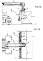
- FIG. 1 The figures in the drawing are side views and top views of a side lift in accordance with the present invention intended for handling of ISO containers and mounted on the boom of a work machine, so that
- the side lift is denoted generally with the reference numeral 10.
- the side lift 10 has been attached to the end of the boom 3 of a work machine 2, and in the situation shown in the figures, the container 1 has been grasped by means of the side lift 10.
- the side lift 10 is, in itself, of conventional construction so that it comprises grasping members 11, by whose means the container 1, in particular the fastening points at the corners of the container 1, are grasped.
- the side lift 10 includes a side support 12, which is supported against the side wall of the container 1 when the grasping members 11 have been attached to the container 1.
- the side lift 10 comprises a telescopic construction 13, at whose ends the grasping members have been fitted so that the side lift 10 can handle ISO containers of different measures. It is a novel and essential feature of the invention and of the side lift 10 that the components of the side lift mentioned above, i.e. the grasping members 11, the side support 12, and the telescopic construction 13 have been mounted on a rotation device 14, by whose means the side lift 10 has been attached to the end of the boom 3 of the work machine 2.
- the rotation device 14 by means of' the rotation device 14, the side lift 10 and the container 1 attached to it can be rotated, in the way illustrated in the figures, around the axis R of rotation of the rotation device 14.
- the container 1 could be rotated in the way illustrated in the figures, it is, however, required that the tilting torque of the load can be minimized as well as possible.
- this has been accomplished so that the grasping members 11, which are supposed to grasp the fastening points provided at the top comers of the container 1, are placed, first, below the rotation device 14 and, second, they have been arranged so that the axis R of rotation of the rotation device 14 has been shifted aside from the line C interconnecting the grasping members 11 to a distance b from said line C towards the vertical plane A placed in the longitudinal direction of the container and passing through the centre of gravity of the container 1.
- the distance between said vertical plane A and the axis R of rotation is denoted with the reference a.
- the joint centre of gravity of the load produced by the container and of the side lift can be made to be located optimally below the suspension point so that the torque of inclining produced by them is as little as possible. Minimizing of this torque of inclining is of particular importance in a situation in which the container 1 has been turned through 90° in the way illustrated in Figs. 2A and 2B. In such a case, if the centre of gravity is placed far from the point of suspension, the torque of inclining produced by the centre of gravity acts as a considerable torque that attempts to overturn the work machine 2.
- the axis R of rotation is placed at a distance a from the longitudinal centre plane A passing through the centre of gravity of the container 1. If necessary, this distance a can be changed, preferably shortened, and according to one alternative, the axis R of rotation can be placed at the plane A.
- the ISO containers are of uniform width, so that, in the planning, in advance, it is easy to construct the equipment so that the torques of inclining that are produced are as little as possible.
- the measures should preferably be arranged so that, when the container 1 is rotated through 90° from the position shown in Figs. 1A and 1B, i.e. into the position shown in Figs.
- the outermost point of the container 1 and so also the outermost point of the side lift 10 placed at the opposite side of the container are placed within the longitudinal outlines of the work machine 2.
- the side lift 10 and the container 1 do not cause any extra width in the solution, for example, when the container 1 is passed through a door opening or through some other location with limited width.
Landscapes
- Engineering & Computer Science (AREA)
- Mechanical Engineering (AREA)
- Transportation (AREA)
- Structural Engineering (AREA)
- Civil Engineering (AREA)
- Life Sciences & Earth Sciences (AREA)
- Geology (AREA)
- Load-Engaging Elements For Cranes (AREA)
- Forklifts And Lifting Vehicles (AREA)
Applications Claiming Priority (2)
| Application Number | Priority Date | Filing Date | Title |
|---|---|---|---|
| FI972898 | 1997-07-08 | ||
| FI972898A FI101956B1 (fi) | 1997-07-08 | 1997-07-08 | ISO-konttien käsittelyyn tarkoitettu sivutarttuja |
Publications (2)
| Publication Number | Publication Date |
|---|---|
| EP0890543A2 true EP0890543A2 (fr) | 1999-01-13 |
| EP0890543A3 EP0890543A3 (fr) | 2000-12-20 |
Family
ID=8549218
Family Applications (1)
| Application Number | Title | Priority Date | Filing Date |
|---|---|---|---|
| EP98660069A Withdrawn EP0890543A3 (fr) | 1997-07-08 | 1998-07-07 | Appareil de manutention de ISO containers par le côté |
Country Status (2)
| Country | Link |
|---|---|
| EP (1) | EP0890543A3 (fr) |
| FI (1) | FI101956B1 (fr) |
Cited By (6)
| Publication number | Priority date | Publication date | Assignee | Title |
|---|---|---|---|---|
| EP1886964A2 (fr) | 2006-08-09 | 2008-02-13 | Italcarrelli Srl | Chariot élévateur pour la manutention de dalles |
| CN102295223A (zh) * | 2011-06-28 | 2011-12-28 | 三一集团有限公司 | 一种吊具及正面吊 |
| NL2005296C2 (nl) * | 2010-09-01 | 2012-03-05 | Fred Korrel | Containerklem. |
| WO2012028027A1 (fr) * | 2010-09-01 | 2012-03-08 | 湖南三一智能控制设备有限公司 | Système d'alignement de conteneurs intelligent et grue à suspension avant pour conteneurs comprenant le système |
| CN103693555A (zh) * | 2013-12-20 | 2014-04-02 | 天津港集装箱码头有限公司 | 岸边起重机用侧向集装箱吊具 |
| US11193287B2 (en) * | 2016-09-23 | 2021-12-07 | Sh Technologies Pte Ltd | Construction system and method |
Families Citing this family (1)
| Publication number | Priority date | Publication date | Assignee | Title |
|---|---|---|---|---|
| CN106976793B (zh) * | 2017-04-19 | 2018-11-09 | 中央军委后勤保障部建筑工程研究所 | 具有快速锁止功能的集装箱吊具货叉机构 |
Citations (1)
| Publication number | Priority date | Publication date | Assignee | Title |
|---|---|---|---|---|
| US4606568A (en) * | 1984-01-04 | 1986-08-19 | Kalmar Lmv | Side lifting apparatus |
Family Cites Families (3)
| Publication number | Priority date | Publication date | Assignee | Title |
|---|---|---|---|---|
| GB1207602A (en) * | 1968-05-13 | 1970-10-07 | Matbro Ltd | Improvements in or relating to vehicles for handling freight containers |
| FR2393757A1 (fr) * | 1977-06-06 | 1979-01-05 | Ppm Sa | Dispositif de manutention de conteneurs |
| DE4236345A1 (de) * | 1992-10-28 | 1994-05-05 | Peter Dipl Ing Neugebauer | Vorrichtung zum Umsetzen und Transportieren von Containern |
-
1997
- 1997-07-08 FI FI972898A patent/FI101956B1/fi active
-
1998
- 1998-07-07 EP EP98660069A patent/EP0890543A3/fr not_active Withdrawn
Patent Citations (1)
| Publication number | Priority date | Publication date | Assignee | Title |
|---|---|---|---|---|
| US4606568A (en) * | 1984-01-04 | 1986-08-19 | Kalmar Lmv | Side lifting apparatus |
Cited By (8)
| Publication number | Priority date | Publication date | Assignee | Title |
|---|---|---|---|---|
| EP1886964A2 (fr) | 2006-08-09 | 2008-02-13 | Italcarrelli Srl | Chariot élévateur pour la manutention de dalles |
| EP1886964A3 (fr) * | 2006-08-09 | 2008-11-26 | Italcarrelli Srl | Chariot élévateur pour la manutention de dalles |
| CN101121492B (zh) * | 2006-08-09 | 2011-03-16 | 意大利卡雷利公司 | 用于搬运板材的升降装卸车 |
| NL2005296C2 (nl) * | 2010-09-01 | 2012-03-05 | Fred Korrel | Containerklem. |
| WO2012028027A1 (fr) * | 2010-09-01 | 2012-03-08 | 湖南三一智能控制设备有限公司 | Système d'alignement de conteneurs intelligent et grue à suspension avant pour conteneurs comprenant le système |
| CN102295223A (zh) * | 2011-06-28 | 2011-12-28 | 三一集团有限公司 | 一种吊具及正面吊 |
| CN103693555A (zh) * | 2013-12-20 | 2014-04-02 | 天津港集装箱码头有限公司 | 岸边起重机用侧向集装箱吊具 |
| US11193287B2 (en) * | 2016-09-23 | 2021-12-07 | Sh Technologies Pte Ltd | Construction system and method |
Also Published As
| Publication number | Publication date |
|---|---|
| FI101956B (fi) | 1998-09-30 |
| FI101956B1 (fi) | 1998-09-30 |
| FI972898A0 (fi) | 1997-07-08 |
| EP0890543A3 (fr) | 2000-12-20 |
Similar Documents
| Publication | Publication Date | Title |
|---|---|---|
| CA2317361A1 (fr) | Contrepoids retractable pour plate-forme de travail aerienne a fleche droite | |
| EP0890543A2 (fr) | Appareil de manutention de ISO containers par le cÔté | |
| WO1987003657A1 (fr) | Crochet de chargement | |
| US6379104B1 (en) | Single side entry container lifting device | |
| CA2189403A1 (fr) | Pallette inclinable et transportable | |
| GB9807024D0 (en) | Two directional industrial sidelift truck with rotatable cab | |
| US7614841B2 (en) | Lifting fork | |
| US5873615A (en) | Grapple | |
| JPH07315785A (ja) | 鞘フォーク及びフォークリフト | |
| FI77829C (fi) | Stockhanteringsanordning. | |
| JPH061574Y2 (ja) | 屋根瓦用搬送具 | |
| US6685248B2 (en) | Object engaging tool and method of manipulating object using same | |
| EP0943579A2 (fr) | Extrémité de flèche à positions multiples et profil bas | |
| CA2223802C (fr) | Grappin | |
| JPH07257894A (ja) | フォークリフトの荷役装置 | |
| SU1676998A1 (ru) | Грузозахватное устройство | |
| SU1245534A1 (ru) | Строительный подъемник | |
| JPH0155134B2 (fr) | ||
| SU1533955A1 (ru) | Захватный орган дл поддонов | |
| SU1350091A1 (ru) | Устройство дл загрузки штучных грузов в транспортное средство с боковым дверным проемом | |
| SU1567511A1 (ru) | Вилочный захват к погрузчику | |
| SU1493551A1 (ru) | Контейнер | |
| SU1399255A1 (ru) | Грузова подвеска крана | |
| RU2026211C1 (ru) | Погрузочно-транспортная машина для сортиментов | |
| SU1623919A1 (ru) | Захватный орган дл поддонов |
Legal Events
| Date | Code | Title | Description |
|---|---|---|---|
| PUAI | Public reference made under article 153(3) epc to a published international application that has entered the european phase |
Free format text: ORIGINAL CODE: 0009012 |
|
| AK | Designated contracting states |
Kind code of ref document: A2 Designated state(s): BE DE NL |
|
| AX | Request for extension of the european patent |
Free format text: AL;LT;LV;MK;RO;SI |
|
| PUAL | Search report despatched |
Free format text: ORIGINAL CODE: 0009013 |
|
| AK | Designated contracting states |
Kind code of ref document: A3 Designated state(s): AT BE CH CY DE DK ES FI FR GB GR IE IT LI LU MC NL PT SE |
|
| AX | Request for extension of the european patent |
Free format text: AL;LT;LV;MK;RO;SI |
|
| 17P | Request for examination filed |
Effective date: 20010620 |
|
| RAP1 | Party data changed (applicant data changed or rights of an application transferred) |
Owner name: KALMAR INDUSTRIES OY AB |
|
| AKX | Designation fees paid |
Free format text: BE DE NL |
|
| 17Q | First examination report despatched |
Effective date: 20020620 |
|
| STAA | Information on the status of an ep patent application or granted ep patent |
Free format text: STATUS: THE APPLICATION IS DEEMED TO BE WITHDRAWN |
|
| 18D | Application deemed to be withdrawn |
Effective date: 20030808 |