EP0890683A2 - Dachkonstruktion - Google Patents
Dachkonstruktion Download PDFInfo
- Publication number
- EP0890683A2 EP0890683A2 EP98112496A EP98112496A EP0890683A2 EP 0890683 A2 EP0890683 A2 EP 0890683A2 EP 98112496 A EP98112496 A EP 98112496A EP 98112496 A EP98112496 A EP 98112496A EP 0890683 A2 EP0890683 A2 EP 0890683A2
- Authority
- EP
- European Patent Office
- Prior art keywords
- support
- roof
- insulation
- groove
- eaves
- Prior art date
- Legal status (The legal status is an assumption and is not a legal conclusion. Google has not performed a legal analysis and makes no representation as to the accuracy of the status listed.)
- Granted
Links
- 238000009413 insulation Methods 0.000 claims description 122
- 238000010276 construction Methods 0.000 claims description 69
- 208000000260 Warts Diseases 0.000 claims description 20
- 201000010153 skin papilloma Diseases 0.000 claims description 20
- 238000007789 sealing Methods 0.000 claims description 19
- 239000005871 repellent Substances 0.000 claims description 10
- 238000009434 installation Methods 0.000 claims description 9
- 239000012774 insulation material Substances 0.000 claims description 7
- 239000011490 mineral wool Substances 0.000 claims description 5
- 239000000725 suspension Substances 0.000 claims description 5
- 230000002093 peripheral effect Effects 0.000 claims description 3
- 239000011248 coating agent Substances 0.000 claims description 2
- 238000000576 coating method Methods 0.000 claims description 2
- 238000013461 design Methods 0.000 description 14
- 238000004519 manufacturing process Methods 0.000 description 14
- 230000008901 benefit Effects 0.000 description 12
- 239000002023 wood Substances 0.000 description 9
- 210000002105 tongue Anatomy 0.000 description 7
- 239000002131 composite material Substances 0.000 description 6
- 230000004888 barrier function Effects 0.000 description 5
- 239000011093 chipboard Substances 0.000 description 5
- 230000003068 static effect Effects 0.000 description 5
- 238000005253 cladding Methods 0.000 description 4
- 230000006378 damage Effects 0.000 description 4
- 230000001419 dependent effect Effects 0.000 description 4
- 229910052751 metal Inorganic materials 0.000 description 4
- 239000002184 metal Substances 0.000 description 4
- 229910052782 aluminium Inorganic materials 0.000 description 3
- XAGFODPZIPBFFR-UHFFFAOYSA-N aluminium Chemical compound [Al] XAGFODPZIPBFFR-UHFFFAOYSA-N 0.000 description 3
- 238000011161 development Methods 0.000 description 3
- 230000018109 developmental process Effects 0.000 description 3
- 230000000694 effects Effects 0.000 description 3
- 238000005516 engineering process Methods 0.000 description 3
- 230000006872 improvement Effects 0.000 description 3
- 238000000034 method Methods 0.000 description 3
- 230000002787 reinforcement Effects 0.000 description 3
- XLYOFNOQVPJJNP-UHFFFAOYSA-N water Substances O XLYOFNOQVPJJNP-UHFFFAOYSA-N 0.000 description 3
- 239000004793 Polystyrene Substances 0.000 description 2
- 238000004873 anchoring Methods 0.000 description 2
- 238000013459 approach Methods 0.000 description 2
- 230000000295 complement effect Effects 0.000 description 2
- 230000008878 coupling Effects 0.000 description 2
- 238000010168 coupling process Methods 0.000 description 2
- 238000005859 coupling reaction Methods 0.000 description 2
- 238000009792 diffusion process Methods 0.000 description 2
- 239000000835 fiber Substances 0.000 description 2
- 210000001061 forehead Anatomy 0.000 description 2
- 238000009415 formwork Methods 0.000 description 2
- 239000011810 insulating material Substances 0.000 description 2
- 230000007774 longterm Effects 0.000 description 2
- 239000000314 lubricant Substances 0.000 description 2
- 229920002223 polystyrene Polymers 0.000 description 2
- 230000008569 process Effects 0.000 description 2
- 230000009467 reduction Effects 0.000 description 2
- 238000012546 transfer Methods 0.000 description 2
- 208000027418 Wounds and injury Diseases 0.000 description 1
- 230000006978 adaptation Effects 0.000 description 1
- 238000005452 bending Methods 0.000 description 1
- 230000005540 biological transmission Effects 0.000 description 1
- 230000015572 biosynthetic process Effects 0.000 description 1
- 239000011449 brick Substances 0.000 description 1
- 239000000969 carrier Substances 0.000 description 1
- 239000001913 cellulose Substances 0.000 description 1
- 229920002678 cellulose Polymers 0.000 description 1
- 230000009194 climbing Effects 0.000 description 1
- 230000007547 defect Effects 0.000 description 1
- 238000006073 displacement reaction Methods 0.000 description 1
- 238000009826 distribution Methods 0.000 description 1
- 239000011888 foil Substances 0.000 description 1
- 238000009472 formulation Methods 0.000 description 1
- 239000003292 glue Substances 0.000 description 1
- 230000005484 gravity Effects 0.000 description 1
- 229910052602 gypsum Inorganic materials 0.000 description 1
- 239000010440 gypsum Substances 0.000 description 1
- 210000003128 head Anatomy 0.000 description 1
- 238000007373 indentation Methods 0.000 description 1
- 208000014674 injury Diseases 0.000 description 1
- 238000003780 insertion Methods 0.000 description 1
- 230000037431 insertion Effects 0.000 description 1
- 238000003754 machining Methods 0.000 description 1
- 239000000463 material Substances 0.000 description 1
- 239000012528 membrane Substances 0.000 description 1
- 239000002557 mineral fiber Substances 0.000 description 1
- 239000000203 mixture Substances 0.000 description 1
- 210000002445 nipple Anatomy 0.000 description 1
- 238000010422 painting Methods 0.000 description 1
- 238000005192 partition Methods 0.000 description 1
- 230000000149 penetrating effect Effects 0.000 description 1
- 239000004033 plastic Substances 0.000 description 1
- 239000011120 plywood Substances 0.000 description 1
- 238000012805 post-processing Methods 0.000 description 1
- 238000009417 prefabrication Methods 0.000 description 1
- 230000036316 preload Effects 0.000 description 1
- 238000002360 preparation method Methods 0.000 description 1
- 238000003825 pressing Methods 0.000 description 1
- 230000002265 prevention Effects 0.000 description 1
- 230000003014 reinforcing effect Effects 0.000 description 1
- 238000009420 retrofitting Methods 0.000 description 1
- 239000000344 soap Substances 0.000 description 1
- 239000007787 solid Substances 0.000 description 1
- 238000012916 structural analysis Methods 0.000 description 1
- 239000000758 substrate Substances 0.000 description 1
- 230000002195 synergetic effect Effects 0.000 description 1
- 230000008719 thickening Effects 0.000 description 1
- 238000012549 training Methods 0.000 description 1
- 230000000007 visual effect Effects 0.000 description 1
Images


Classifications
-
- E—FIXED CONSTRUCTIONS
- E04—BUILDING
- E04D—ROOF COVERINGS; SKY-LIGHTS; GUTTERS; ROOF-WORKING TOOLS
- E04D13/00—Special arrangements or devices in connection with roof coverings; Protection against birds; Roof drainage ; Sky-lights
- E04D13/04—Roof drainage; Drainage fittings in flat roofs, balconies or the like
- E04D13/064—Gutters
- E04D13/072—Hanging means
- E04D13/0722—Hanging means extending mainly under the gutter
-
- E—FIXED CONSTRUCTIONS
- E04—BUILDING
- E04B—GENERAL BUILDING CONSTRUCTIONS; WALLS, e.g. PARTITIONS; ROOFS; FLOORS; CEILINGS; INSULATION OR OTHER PROTECTION OF BUILDINGS
- E04B7/00—Roofs; Roof construction with regard to insulation
- E04B7/02—Roofs; Roof construction with regard to insulation with plane sloping surfaces, e.g. saddle roofs
- E04B7/04—Roofs; Roof construction with regard to insulation with plane sloping surfaces, e.g. saddle roofs supported by horizontal beams or the equivalent resting on the walls
-
- E—FIXED CONSTRUCTIONS
- E04—BUILDING
- E04B—GENERAL BUILDING CONSTRUCTIONS; WALLS, e.g. PARTITIONS; ROOFS; FLOORS; CEILINGS; INSULATION OR OTHER PROTECTION OF BUILDINGS
- E04B7/00—Roofs; Roof construction with regard to insulation
- E04B7/18—Special structures in or on roofs, e.g. dormer windows
-
- E—FIXED CONSTRUCTIONS
- E04—BUILDING
- E04B—GENERAL BUILDING CONSTRUCTIONS; WALLS, e.g. PARTITIONS; ROOFS; FLOORS; CEILINGS; INSULATION OR OTHER PROTECTION OF BUILDINGS
- E04B7/00—Roofs; Roof construction with regard to insulation
- E04B7/20—Roofs consisting of self-supporting slabs, e.g. able to be loaded
- E04B7/22—Roofs consisting of self-supporting slabs, e.g. able to be loaded the slabs having insulating properties, e.g. laminated with layers of insulating material
-
- E—FIXED CONSTRUCTIONS
- E04—BUILDING
- E04D—ROOF COVERINGS; SKY-LIGHTS; GUTTERS; ROOF-WORKING TOOLS
- E04D13/00—Special arrangements or devices in connection with roof coverings; Protection against birds; Roof drainage ; Sky-lights
- E04D13/02—Roof-covering aspects of dormer windows
-
- E—FIXED CONSTRUCTIONS
- E04—BUILDING
- E04D—ROOF COVERINGS; SKY-LIGHTS; GUTTERS; ROOF-WORKING TOOLS
- E04D13/00—Special arrangements or devices in connection with roof coverings; Protection against birds; Roof drainage ; Sky-lights
- E04D13/03—Sky-lights; Domes; Ventilating sky-lights
- E04D13/0305—Supports or connecting means for sky-lights of flat or domed shape
- E04D13/031—Supports or connecting means for sky-lights of flat or domed shape characterised by a frame for connection to an inclined roof
-
- E—FIXED CONSTRUCTIONS
- E04—BUILDING
- E04D—ROOF COVERINGS; SKY-LIGHTS; GUTTERS; ROOF-WORKING TOOLS
- E04D3/00—Roof covering by making use of flat or curved slabs or stiff sheets
- E04D3/38—Devices for sealing spaces or joints between roof-covering elements
-
- E—FIXED CONSTRUCTIONS
- E04—BUILDING
- E04G—SCAFFOLDING; FORMS; SHUTTERING; BUILDING IMPLEMENTS OR AIDS, OR THEIR USE; HANDLING BUILDING MATERIALS ON THE SITE; REPAIRING, BREAKING-UP OR OTHER WORK ON EXISTING BUILDINGS
- E04G21/00—Preparing, conveying, or working-up building materials or building elements in situ; Other devices or measures for constructional work
- E04G21/14—Conveying or assembling building elements
- E04G21/16—Tools or apparatus
Definitions
- the present invention relates to a roof structure with at least one an eaves or foot purlin and / or on a middle purlin and / or on one Ridge purlin supported basic construction according to the roof covering Preamble of claim 1 and a support and insulation element according to the preamble of claim 7.
- the invention further relates to a dormer structure according to Preamble of claim 9, a roof structure according to the preamble of the claim 13, an eaves piece according to the preamble of claim 16 and an assembly aid according to the preamble of claim 18.
- roofs for buildings such as Residential houses by laying so-called roof trusses made of load-bearing beams and applied sections in their Basic construction manufactured. Between the divisions and / or the divisions then insert or apply insulation. According to newer technology, the insulation installed as so-called partition insulation, the lower heat and air passage joints Has. Form the divisions with the installed or applied roof insulation the basic construction of these roofs, which then supports the roof covering.
- the sub-trades completed first, e.g. the sub-roof in shape a foil covering are ongoing through the following sub-trades exposed to the risk of damage.
- the lower layers usually require further local work by cladding with gypsum boards or wooden straps, which are then from the following Craftsmen such as the plasterer or carpenter are to be executed. This leads to naturally to a costly and time-consuming roof construction.
- connection points between the dormer elements and the basic structure can only be sealed with great effort.
- connection points are mostly a metal cladding required because the connection points hardly create a seal per se.
- the laying of plate-shaped bodies is also particularly useful large format plates sometimes difficult because they can warp and therefore Bumps and arches occur.
- This problem is particularly with wood or Fibreboard known.
- a plywood structure is often used as a countermeasure chosen, but is also not suitable to prevent curvature in any case. Due to the warpage of such panels, it is when laying them on one Underground or a coupling to an existing plate element is required, that the curvature was overcome with a certain amount of force becomes. This is disadvantageous in particular in the case of supporting elements for a roof structure, since here in an unfavorable area to work on the roof slope. Lie bad weather conditions, this may be even especially dangerous and therefore partly hardly feasible.
- the document DE-OS 21 45 628 discloses a support and insulation element for one Roof structure, in which the outer peripheral edge of a box-like frame of a first support and insulation element has a hook section, which in one adapted hook section engages in the adjacent support and insulation element.
- the hook section of the one supporting and insulating element is in the correct position to be placed over the hook section of the other support and insulation element.
- the hook sections can be so flexible and with undercuts be designed that the indentation of thickening of a sidebar in the recesses of the other sidebar is possible, creating a firm connection between two plates.
- the neighboring supporting and However insulation elements are first positioned and fixed exactly to each other on the roof and there is an additional assembly step for pressing the hook sections together required. This construction is therefore disadvantageous in that it requires a large amount of installation and precise work is required.
- the present invention is therefore based on the object, while avoiding it of the defects discussed above to further develop a roof structure such that a weather-resistant basic construction is made available, for example can be quickly installed in almost any weather using a construction crane.
- the roof construction according to the invention enables for the first time an economical, efficient roof construction.
- the one with conventional roof constructions during manufacture the basic construction until just before the roof covering and until just before the final completion of the inner surface of various work processes which can be carried out at the construction site with a high risk of errors thus moved to the workshop for the first time and thus brought forward.
- By the Construction of the basic structure through the use of weather-insensitive, prefabricated support and insulation elements can be a weather-insensitive for the first time Basic construction can be created. This is advantageously done by a rapid, Labor-saving laying of the prefabricated support and insulation elements by means of a construction crane, this step is then almost independent of the weather.
- the support and insulation elements can be simply placed on and in one another be applied to the purlins, with only one man to drive in and if necessary, another man is needed for fastening. This is significantly fewer workers, like laying traditional rafters and purlins Roof structures are needed.
- a support and insulation element is with the neighboring support and insulation element by means of a triangular or hook-shaped designed outer edge positively connected, the first support and Hooks the insulation element into the next support and insulation element.
- this joint By appropriate preparation of this joint, preferably by painting with a lubricant such as Soft soap can significantly affect this sliding effect be improved. It is then advantageously not necessary to wedge or Tension-producing connection in the manufacture of the hollow box-like Planing frame. It is sufficient, for example, if this joint has a fast-running Circular saw in diagonal cut at low thrust for a smooth Cut surface is produced.
- the complete support and insulation element fulfills the building physics and static requirements already because of the hollow box-shaped Formulation quasi a hollow beam arises, which advantageously follows the following building physics Consistencies shows:
- the one mounted on the lower side of the hollow box-shaped frame, towards the roof interior facing plate is preferably relatively dense and strong vapor retardant.
- the following between the legs of the frame in the hollow box created Arranged thermal insulation can be made from a wide variety of insulation materials become. Insulation materials made of mineral fibers or insulation panels made of cellulose packages are preferred Application.
- a layer of air that may lie above the insulation layer forms another Insulation element.
- a narrow wooden plate or wooden strip can be found be applied to the legs of the frame.
- One is preferably something above that softer, upper cover plate arranged, which has a lower vapor diffusion resistance like the bottom plate.
- This is treated to be water-repellent, e.g. siliconized, impregnated or provided with a water-repellent layer.
- the wooden bar can selected from particularly stable wood, quasi like the upper half of a beam, while the lower half of such an imaginary beam through the hard lower shell is pictured. This can be indicated if the softer or more vapor permeable Upper layer or upper plate does not have such a high static load-bearing capacity and still larger spans should be achieved.
- the installation of a Vapor barrier or barrier e.g. on the inside is also possible, like the Reinforcement of the lower layer by wallpapering etc.
- the water-repellent treated surface or the water-repellent coating should at least withstand temporary wet loads. However, it needs do not represent a permanent roof membrane. Over this level it is now possible in the simplest Shape, any quick roofing with a suitable roofing and also to apply the conventional tile roof. Even the manufacture of flat roofs is possible with it.
- the side bond can so that over the joints of the abutting and interlocking support and insulation elements do not draw in water, preferably with one seal arranged in the groove base.
- a seal a fine, sealing, self-expanding cord is preferably used for this. In order to the air density is also significantly improved.
- the roof construction according to the invention differs in an advantageous manner for example by the following features compared to a conventional rafter construction:
- the frame can be made Bars or divisions.
- the side parts or legs Preferably the frame is made up of two or three glued layers. This creates a warp resistant, particularly stable frame. This is in conflict for traditional solid wood rafters that can twist.
- the support and insulation element according to the invention no longer has any knobs (notches), with which the rafters are combed onto the purlins, but it preferably points attached, horizontally running strip-like cams or wart strips on the statically calculated and fixed accordingly and that on a corresponding Place the nipple on the purlin or in corresponding notches intervention.
- the wart strips attached to the support and insulation element can also be integrally formed on the frame.
- the outer dimension for the support and insulation element has a size of about 1.25 mx 6 m with a height of about 140 to 220 mm has proven to be particularly advantageous. This size is also easy in medium-sized craft businesses such as e.g. a joinery and / or carpentry.
- the width dimension and the length dimension are not permanently limited. The latter preferably depends on the depth of the house. It can therefore also very deep roofs are made. Roofs with a depth of 6 to 8 m or roofs with a depth of 8 to 14 m as well as roofs with a depth of 12 to 18 m can be easily realized with the roof construction according to the invention.
- the support and insulation element according to the invention should be at least a depth of approximately Bridge 6 m, which would then correspond to a house depth of about 11 to 12 m, which in the usual housing are usually required.
- the hollow box-like frame can protrude above the middle purlin, so that no ridge purlin is needed and instead the ridge-side edges of two abutting support and insulation elements connected to each other in a mutually opposing manner become.
- a triangular element or a Screwed on triangular dam element which is provided with a rod and hat profile from above can be.
- the support and insulation elements can be used for stiffening both in their longitudinal direction as well as in their transverse direction between the hollow box-shaped frame stiffening middle rungs are provided.
- the fastening is no longer as before by the insulation layer and the Rafters created with a long screw or an long nail, but over the wart-shaped Conditions on the lower side of the support and insulation element and on the Purlin top.
- the quality of the roof structure can thus be after laying the support and insulation elements are checked from below, which is a significant reduction the risk of injury. There is no need for the laying itself Man climbing around more on the roof, making it the first time even when wet Weather-proof installation enables it to be done much faster can be than before.
- the roof structure according to the invention also includes due to the in a kind of series production of the support and insulation element considerable cost-saving rationalization advantages. Because there are 1.25 m wide parts Insert roof windows as well as standing dormers into the dimensional structure without any problems there are no obstacles, even for more complex configurations. About that In addition, the supporting and insulating elements according to the invention can be simplified Shape can also be used for large roof overhangs.
- a seal in the groove base which is preferably designed as a sealing cord for sealing two abutting support and insulation elements can improve another seal in the area of the joint of the edges adjacent upper plates can be provided. In doing so, their side edges be held diagonally from the top outside down to the inside, so that two adjacent Edges of upper plates a triangular or trapezoidal narrow gap form that of the seal, for example of a self-expanding sealing cord is fully filled.
- the downward-facing edge of the top plate of a support and insulation element beveled from below and protrude beyond the lower edge of the frame, so that they are on the upper plate of the support and insulation element arranged below Edge area comes to rest, this upper plate corresponding in the edge area is chamfered so that a constantly downward water drainage is guaranteed becomes.
- a sealing cord can be provided between cost-saving improvement of the seal.
- a dormer structure is provided provided with the features of claim 9. This solves the invention This is also a task, as it can be done quickly and almost with simple means can be set up in any weather.
- the roof slider construction according to the invention thus enables for the first time Cost-effective and efficient design due to the prefabricated side carriers. This can reliably by means of the spring-like projection designed there trained edge elements of the basic structure engage, which in one A stable installation of a side carrier is possible.
- the technology of the roof structure according to the invention is prepared so that a prefabrication the side carrier can be done in a workshop and the side carrier on the Roof only need to be inserted into the basic structure. This onset can be done by crane or manually, depending on the circumstances.
- the groove-like recess or the spring-like Projection have an oblique sliding surface are triangular.
- the side supports are only engaged with the edge elements of the basic construction bring, then then automatically slipping into the side carrier, so that the connection is automatically in the correct position. So that's one positive and due to the weight of the side straps also a non-positive Connection between the components made.
- Another advantage of the present invention is that the risk of Assembly errors is significantly reduced. Through the prefabricated elements and the Predefined geometry at the connection points are hardly any errors during assembly possible.
- the side carrier with the spring-like projection is attached to the outside of the side wall.
- This alternative design allows the side wall of the dormer as a continuous wall e.g. with already integrated insulation prefabricate. This also allows better and more uniform insulation effects can be achieved in this area.
- edge element of the basic construction in the area of the side girders Has intermediate element that cooperates on one side with the basic structure and on the other side a groove-like depression for the tongue-like projection in the side member of the dormer can advantageously be larger Dormer load a kind of reinforcement beam are pulled in.
- This The intermediate element can be used to create a groove-like depression on both sides of the dormer window provide, even if the edge element of the basic structure on a Side would offer a feathery head start.
- Roof dormer construction easily integrated into a roof construction are arranged in the support and insulation elements next to each other and via appropriate triangular grooves and tongues are positively or non-positively connected are.
- the edge element of the basic construction in upper area of the dormer window has at least one connecting part, which with a groove-like recess is provided, in which a tongue-like projection from the top Closing elements of the dormer engages. It can also be used in the upper end area the dormer to the building roof a quick assembly with simple means produce. Due to the triangular tongue and groove connection also present there with an inclined sliding surface can be a particularly good one with little effort Connection can be made. This would also allow the dormer to be essentially completely prefabricated and put on the roof as a whole using a crane and bring it into the predetermined position via the sliding surfaces. The effort for Production of the dormer window and, in particular, a possible hazard for working people People can be significantly reduced.
- the dormer window has at least one post, which is attached to the side member via preferably two oarlocks. Then there is also one traditional construction of the dormer window possible on the basis of the side beams, the post sits securely over the oarlocks on the side beams and in his Location is fixed.
- the side walls with the side supports and / or the upper connection elements also be prefabricated as a finished part, which results in a very fast and easy installation of the dormer on site.
- the prefabricated wall parts can are easily manufactured in a workshop. This allows one more Reduction of assembly times and assembly effort on the construction site.
- a roof structure provided with the features of claim 13, which is a basic construction, which has a roof covering and a gutter.
- This too Design solves the task, as this means that the assembly and time required Functional installation of a gutter can be significantly reduced.
- the gutter with the at least one eaves piece into the groove on the eaves-side end of the basic construction Because of this Hooking the eaves piece into the groove allows the rain gutter to be attached to the roof very quickly and with simple means. Any subsequent fixation by means of nails, screws or the like can then be carried out without great effort to hold the rain gutter.
- the roof construction according to the invention advantageously offers the first time Possibility to determine a gutter slope in advance using simple means. Since that at least one eaves piece here has a corresponding presetting due to its shape is advantageously not an individual adjustment of each gutter bracket required. The work involved is therefore eliminated. In particular, the adaptation of the at least one eaves piece in a workshop or similar take place, which simplifies the work considerably and is more economical.
- Another advantage is that a working person is thus much less long on the scaffolding or on the roof, which means a much smaller one There is a danger to humans. The workload is also reduced for a tinsmith or the like on site at the eaves clearly.
- the at least one eaves piece can be well in insert the analog groove into the basic construction and with simple means such as a nail or screw connection. Since that too Gutter brackets, for example, by a nail or screw connection to the at least one eaves piece can be attached, a tinsmith according to the invention Use of additional tools such as a chisel for machining of rafters and the like when working on the eaves.
- the invention Roof construction thus allows a very quick and effortless installation of a gutter to.
- the groove is triangular in shape that a oblique surface is present, and the eaves piece in cross-section is correspondingly triangular trained projection.
- the inclined surface of the groove can then be used as Sliding surface for the insertion of the eaves serve, whereby the assembly of the at least a eaves piece on the eaves-side end of the basic construction is further facilitated becomes.
- the center of gravity of the eaves piece can be placed so that it remains in the groove by itself or with less effort until it is fixed is made.
- the triangular shape the groove allows a better connection to the eaves-side end of the basic construction is because nails or screws penetrate a larger area of the eaves piece, if they are passed through the resulting wedge-shaped projection.
- the at least one eaves piece is pre-assembled on the gutter, it can be arranged together with this on the eaves-side end of the basic structure, which further reduces the assembly steps in this dangerous area.
- At this embodiment is only an attachment of the at least one Eaves piece required on the basic construction, with the gutter slope automatically sets. This reduces the workload in the area of the eaves further.
- the base for each holding device Gutter can be fixed without errors in the manufacture of the gutter slope possible are. Due to its shape, the eaves piece does not leave any wrong arrangement to. This further simplifies assembly.
- an eaves piece for connecting a rain gutter to a basic structure of a roof structure provided, which also solves the task and the characteristic features of claim 16.
- an assembly aid provided with the features of claim 18. This also serves as a solution the object of the invention, since hereby plate-like body with simple means can be planned if necessary.
- the assembly aid according to the invention is characterized by a very simple construction from, but a very high functionality can still be achieved.
- the hangers are only to be anchored to the plate-shaped bodies, with the wedge element when inserting a good power transmission is achieved.
- the driving in the wedge can be done by a conventional tool such as a Hammer done.
- the plate aligns itself by overcoming it Preload gradually out and then on the substructure or attached to the adjacent plate element. That loosen the assembly aid can then also be done with very simple means. For this is only the wedge element out of the hooks again. The hangers can then be removed.
- the hanging devices are tubular and in particular a rectangular one Have cross-section, will also advantageously good guidance for created the wedge element to be trained accordingly. Tilting of the wedge element or twisting, as is the case, for example, with a round design of the Hanging device would be possible can be avoided even more effectively.
- the wedge element has a wedge section and a cuboid section, can be used to pull the plate into the desired level using the Wedge bevel as well as for holding in this area through the cuboid section be used.
- the load on the wedge section when fully inserted by pre-stressing the arched plate can reliably from the cuboid section be collected without the wedge portion being further stressed. This increases the service life of the assembly aid according to the invention continues.
- the hanging devices by means of a screw connection are anchored in the plate-shaped bodies. Then they can be reliable can be coupled to it and is also easy to disassemble after fastening the curved plate on the surface possible.
- the hooks of the assembly aid can often be used.
- a first embodiment of a roof structure according to the invention is in the 1 to 11 are shown.
- FIG. 1 in cross section of an embodiment of the basic construction 1 of a roof construction 2 according to the invention, two rows of supporting and insulating elements 4 are arranged one above the other. This is usually the case for roofs with a depth T D over 12 m.
- the support and insulation elements 4 are arranged in rows next to one another, which, however, cannot be seen in the section.
- the supporting and insulating elements 4 are supported in the area of their lower end 6 on the purlin or eaves purlin 8.
- these are additionally supported in the area of their upper end 10 either on the ridge purlin 12 or the central purlin 14.
- the basic construction 1 created from supporting and insulating elements 4 carries the Roof covering 16, which is conventionally used as a tile covering or otherwise, e.g. can be designed as an aluminum sheet covering, as can be seen from FIG. 2.
- the support and insulation element 4 is, for example, as shown in Fig. 3 or 4, formed as a frame 20 from four wooden beams or rafters 22. These wooden beams 22 can be approx. 30 mm to 60 mm thick and have a height of approx. 140 to 220 mm. However, any other dimension is also conceivable, depending on the roof load to be mastered, Wind load and snow load according to the requirements of the static calculations.
- the Rafters or legs 22 of the frame 20 can also be made of multi-glued layers of wood be constructed. Here, strips can also be used, so that in Principle any strength and height is possible. One sensibly becomes the measure grading in 10 mm steps, for example. Apart from that, anyone else can Frame construction can be provided.
- Aluminum profiles should be a good alternative for reasons.
- a plate 24 made of wood, for example. Their facing the roof interior Surface can be, for example, with real wood panels, hard fiber wood decor panels or the like other interior linings which can also be papered 25 be coated.
- the top is, for example, by a chipboard 26, the has been treated water-repellent, for example with a water-repellent Cover layer 27 can be provided, closed.
- the bottom and top can however, both should also be covered with waterproof chipboard.
- the insulation material 28 this as mineral wool insulation felt or mineral wool insulation board or similar well-formed insulating materials can be. The selection of the insulation material can easily be based on the building physics Judge calculations and the client's wishes. Furthermore, the arrangement a vapor barrier or brake possible.
- FIG. 2 on the roof structure 2 according to the invention shown in FIG. 1 reveals the modular structure.
- At least one further, upper row 32 of supporting and insulating elements 4 is arranged above a first, lower row 30 of supporting and insulating elements 4 in the roof type shown.
- This is usually necessary if roof depths T D in the range of 12 to 18 m are to be achieved. Roof depths T D of 6 to 8 m can still be achieved with a series of support and insulation elements 4. With roof depths T D of 8 to 14m, this is still possible.
- FIGS. 1 and 2 are views of one shown in FIGS. 1 and 2 Roof structure 2 in the areas around a ridge purlin 12, around a foot purlin 8 and schematically illustrated around a middle purlin 14.
- the support and insulation element 4 points on its underside or on its lower planking or on the lower one Chipboard 24 on a first wart bar 34 with which the support and insulation element 4 against the foot purlin 8 and / or against a corresponding one attached to the foot purlin Wart bar 36 supports or into a corresponding notch 37 in the foot purlin 8 snaps into place.
- the support and insulation element 4 is at least one further wart ridges 38 attached to its underside against the middle purlin 14 and / or a wart strip 40 attached to the middle purlin or a corresponding one Notch stored.
- the support and insulation element 4 is supported in the upper one Area against the ridge purlin 12 and / or against a wart bar attached to it 42 or a Dreickesdamm in an analogous manner, if necessary directly or through another wart strip 44 attached to the underside.
- the at the upper end of the carrying and Insulated wart bar 38 or 44 can also be integral to the top Shaped or formed frame section forming beams or rafters be.
- the supporting and insulating elements 4 in FIG. 4 are the hook-fold-like configuration in the form of triangular depressions or elevations of the outer circumferential Edge 46 of the support and insulation element 4 can be seen.
- a spring 48 am Edge 46 of a support and insulation element 4 engages in a groove 50 in the edge 46 of the adjacent support and insulation elements 4.
- Groove 50 and tongue 48 are mutually designed accordingly and have an inclined sliding surface 52. This ensures that when two supporting and insulating elements 4 are joined together for example, to connect them tightly with each other solely by their own weight.
- a sealing cord can be placed in the groove base 54 are provided.
- the support and insulation element 4 is for example formed as a frame from four wooden beams or rafters 22, for example can be built up from multiple glued layers. Their strength is determined primarily according to the loads to be managed. Other frame construction, like e.g. a frame made of aluminum profiles are also conceivable.
- the bottom is through a plate 24, for example made of wood to the roof interior.
- the Plate 24 is preferably relatively dense and highly vapor retardant. Their to the roof interior facing surface can be coated with interior panels.
- a vapor barrier on the outside or inside on the support and insulation element 4 is possible.
- the top forms, for example, a water-repellent chipboard 26, whose vapor diffusion resistance is lower than that of the lower plate 24. Due to the water-repellent treatment of the surface of the plate 26 or yourself, can possibly on the application of a layer of roofing or tar cardboard on the weather side Area to be waived.
- the insulation material is located in the interior 56 of the support and insulation element 4 28.
- a mineral wool insulation felt or mineral wool insulation boards be used.
- Other insulation materials can be used just as well.
- For distribution of the support and insulation element can be both in the longitudinal direction and in the transverse direction arranged middle rungs 58 and 60 are inserted. Their number judges depending on the desired stiffening and the expected loads.
- the groove base described is preferably the one described above formed as a sealing cord 54 seal for sealing two together butting support and insulation elements 4 use.
- a further seal 62 in the region of the abutting edges upper plates 26 are provided.
- their side edges 64 beveled diagonally from the top outside down to the inside, so that two adjoining Edges 64 of upper plates 26 a predetermined triangular or trapezoidal or form dovetail-shaped narrow gap 66 which is separated from the seal 62, for example, is filled in completely by a self-expanding sealing cord.
- This top plate is correspondingly bevelled in the edge area 72, so that a steadily downward pointing water drainage is guaranteed.
- a seal 74 arranged between the wart strips 34, 38 and 42, preferably again a sealing cord can be provided.
- Fig. 9 shows the interior of two abutting support and insulation elements 4 an embodiment in detail.
- the panels facing the interior 24 are undercut obliquely on their end faces, so that a composite or Press point on an edge results.
- This press point is preferably on the inside the roof structure 2 in front and serves as an additional seal against moisture in this area.
- a sealing element can also be formed in the space formed by the bevels to be ordered.
- a groove on the edge 46 of a support and insulation element 4 may be formed.
- a sealing cord can be placed in this groove or similar arrange, which provides an even better seal against moisture becomes.
- the visual appearance could be on the inside through training a dummy joint can be improved, as shown in Fig. 10.
- 11 is still an alternative sealing method is shown.
- a sealing lip is embedded in the plate 24, a dummy joint can also be formed.
- FIG. 12 shows a first embodiment of a dormer structure 101.
- the sectional view shown represents a portion of the dormer, in which a side part of the dormer is connected to the roof structure.
- the dormer structure 101 has a basic structure 102, which carries a roof covering 103 with battens and roof tiles. Furthermore, the Dormer structure 101 on a dormer 104, which in the figures only in Sub-areas is shown.
- the basic structure 102 has a plurality of arranged side by side and form-fitting or non-positively connected support and insulation elements 121 on, which are made up of a box-like frame and inside insulation exhibit.
- Such a basic construction 102 can correspond to the basic construction 1, as explained above with reference to FIGS. 1 to 11.
- the support and insulation element 121 has an edge element 122, in which one groove-like recess 123 is formed.
- This groove-like depression 123 is in cross section so triangular that it creates an inclined sliding surface.
- the dormer 104 generally has a side wall 141 on both sides, which in the connection area to the basic structure 102 each contains a side support 142.
- the side bracket 142 is formed with a spring-like projection 143.
- the groove-like depression 123 and the tongue-like projection 143 are here complementary, so that their inclined sliding surfaces on each other when mounting slide off and thus automatically establish a positive or non-positive connection.
- the side bracket 142 is in the Sidewall 141 integrated.
- the side wall 141 also has posts, one External formwork, a windbreak, an insulating layer and an inner lining.
- the side wall 141 can be prefabricated in an external workshop as well be built in the traditional manner on the side support 142.
- corner area between the side bracket 142 and the basic construction 102 can also be a metal panel or the like. for sealing against rain, snow and the like may be provided.
- FIG. 13 shows a further embodiment of a dormer structure according to the invention 101 '.
- a side bracket 142 ' attached to a side wall 141 'on the outside. This allows the side wall 141 ' be formed uniformly, as shown in Fig. 13. Then the constructive one Less effort for the production of the side wall.
- connection between the side carrier 142 or 142 'and the edge element 122 additionally by nails, screws or others Fasteners fixed.
- the sliding surfaces can also be provided with a lubricant, so that they slide better off each other.
- a sealing element can be arranged, which for an even better seal worries.
- FIG. 14 shows a further embodiment, according to which between the Basic structure 102 and the side support 142 an intermediate element 124 in shape a reinforcing bar with a width adapted to the application is.
- the intermediate element 124 is complementary to the on both sides Edge element 122 or to the side support 142 and is used, for example, for Reinforcement due to larger dormer loads.
- the basic construction 102 consists of a plurality of supporting and insulating elements 121 exists side by side with the help of such a groove-like depression and a corresponding spring-like projection can be connected, the case occur that on the dormer side not shown in the figures at the edge area there is a spring-like projection of the support and insulation element.
- the side support 142 of the dormer 104 can then be a differently designed intermediate element be arranged between the side support and the edge element, which offers a groove-like depression on both sides.
- a post 144 of the sidewall 141 about two oarlocks 145 to be fixed on the side member 142, which in particular a formation of the side wall on site, that is, in the case of a non-prefabricated side wall element is an advantage.
- the cut-outs for the oarlocks 145 can be used here are made in advance so that the post 144 is only placed on the side bracket 142 must be and if necessary is glued.
- the Basic structure 102 To connect the upper area of the dormer window to the roof structure, the Basic structure 102 also has an edge element in this area, which is provided with a groove-like depression. Complementarily designed upper connection elements the dormer can engage in this groove-like depression and so Establish a fast and automatic connection in this area too.
- the ceiling of a dormer window can also be attached to the be coupled to the upper edge regions of the side walls 141 or 141 '.
- At the bottom Connection area of the dormer can be a preferably insulated cross member be arranged, which in a tongue or groove of an underlying support or Insulating elements of the basic structure 102 engages and thus a stable coupling creates.
- the dormer window 104 could also be formed essentially completely in advance and are placed on the roof with a crane.
- the side straps with the side wall and the upper connecting elements of the dormer can then with relatively little effort taking into account the sloping roof in advance in a workshop getting produced.
- the entire dormer is due to the sliding surfaces Set down on the basic construction automatically slide into the correct position.
- the invention thus creates a dormer structure 101 or 101 'with a the roof covering 103 supporting basic structure 102 and a dormer window 104, which overlaps a recess in the basic structure 102.
- the Dormer 104 prefabricated side beams 142 and 142 'on a spring-like Have projection 143, which in a corresponding groove-like recess in the edge element 122 of the basic structure 102 engages.
- the groove-like recess 123 or the spring-like projection 143 formed triangular such that an inclined sliding surface is created, which when the side carrier 142 or 142 'is placed on the Basic construction 102 an automatic transfer to the desired position under Production of a positive or non-positive connection enables. So that with little time and Personnel expenditure a reliable and inexpensive production of a dormer 104 possible in any weather.
- a roof structure 201 has a basic structure 202 on, which carries a roof covering 203 and on the eaves side A rain gutter 204 is arranged at the end.
- the gutter 204 is over an eaves section 205 connected to an edge element 221 of the basic structure 202.
- the edge element 221 has a triangular groove 222.
- this groove 222 engages an analog projection 251 of eaves piece 205.
- the eaves piece 205 is such in the present embodiment according to FIG. 17 trapezoidal that it also has a contact surface for holding devices 241 Has gutter 204. In the present embodiment there is one eaves piece 205 is provided for each holding device 241. A height h of each eaves piece 205 is chosen so that the gutter 204 does not slope towards this downpipe shown has. Each eaves piece 205 therefore has a different one Height h up.
- the individual eaves pieces 205 are each screwed or nailed in advance to the holding device 241. Then they will Holding devices 241 with eaves pieces 205 each in their place on the eaves side Bring the end of the basic structure 202. The wedge-shaped projection 251 of the Eaves piece 205 is finally placed on the inclined sliding surface of the groove 222 and inserted into this. The eaves piece 205 is then fixed in the groove 222 by Nailing or screwing through the wedge-shaped projection 251. To the Sealing and closing the space between the top edge of the eaves section 205 or the holding device 241 and the upper edge of the basic structure 202 a plastic or elastic cementing 206 can be introduced.
- each eaves piece 205 has a different height h, the result is one correct arrangement of eaves 205 automatically a desired slope towards the downpipe.
- eaves piece 205 a single elongated piece can also be used Eaves piece, which is designed with varying heights.
- longer gutters 204 in which a downpipe is arranged in a central region, can also two or more longer eaves pieces can be provided, each with several holding devices Overlap 241.
- the groove in the basic construction can also be designed so that it that receives at least one eaves piece in a form-fitting manner. This is then in the side Insert groove. Additional means for fixation can then essentially be dispensed with become.
- the at least one eaves piece 205 can alternatively also first on the edge element 221 are fixed before a holding device 241 is fixed on the eaves piece 205 becomes.
- the at least one eaves piece 205 can have on the side facing away from the gutter 204 have a step into which a hook section of the holding devices 241 engages positively. This increases the Stability of the arrangement continues.
- the at least one eaves piece 205 can also be provided with one rectangular cross section. This would reduce the effort to produce the eaves piece 205. Then when assembling to ensure that each eaves piece 205 really completely in the analog trained Groove on the edge element 221 is inserted.
- the roof structure 201 according to the invention can also be particularly advantageous Use in conjunction with a support and insulation element as it does has been described with reference to FIGS. 1 to 11.
- This support and insulation element exists from a box-like frame, the peripheral edge of which has a spring-like projection or has a corresponding groove-like depression.
- the groove or the spring is so triangular that they have an inclined sliding surface. If the basic structure 202 of the roof structure 201 from such supporting and insulating elements a triangular groove 222 can be formed on the eaves side End of the basic construction 202. A special step in design this groove 222 is then no longer required. The effort for the production and assembly of the roof structure according to the invention is reduced further.
- the invention thus creates a roof structure 201 in which a rain gutter 204 quickly and easily to an eaves-side end of a basic structure 202 can be added, a desired gutter slope advantageously automatically due to the special design of the eaves piece according to the invention 205 results. If the at least one eaves piece 205 also in advance with the holding devices 241 of the gutter 204 is connected, the decrease from one Scaffolding or work required from the roof. A working person must therefore do not stay in this dangerous area for as long as it does in State of the art is the case and do not carry out such extensive work there.
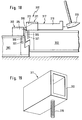
- an assembly aid 301 is used for leveling a loose, self-arching plate 302 against a substrate, plate 302 engages a plate 303 already attached to the ground brought.
- the assembly aid 301 has two suspension devices 311 and 312, which each have a pipe section 313 and 314 and a rigidly connected threaded section 315 and 316 included.
- the pipe sections 313 and 314 are in cross section rectangular.
- threaded sleeves are provided in the plates 302 and 303 in advance 321 and 331 have been introduced, into which the threaded sections 315 and 316 are screwed in.
- the hooks 311 and 312 are used to align the loose plate anchored in alignment with one another at the edge region of the plates 302 and 303.
- a wedge element 317 of the assembly aid 301 is then by means of a hammer 304 through a suspension device 311 hammered into the other suspension device 312.
- the wedge element 317 has a wedge section 318 and a cuboid section 319 on. As shown in FIG. 18, the wedge section 318 also allows larger ones Bulges of the loose plate 302 thread the wedge element 317 into the second Hooking device 312.
- the wedge element 317 can then Example by means of a nose, as shown in Fig. 18, again from the hanging devices 311 and 312 are knocked out.
- the hangers 311 and 312 can then be unscrewed and then again at another point use.
- the hanging devices 311 and 312 can also have a different shape a rectangular cross-sectional shape.
- a rectangular cross-sectional shape comes one, for example polygonal or round design as well as a U-shaped shape, which on the two legs additional flanges for attachment to the Have plate 302 or 303.
- the anchoring of the hangers 311 and 312 on the plates 302 and 303 can also be done in other ways.
- here is a nailing or a Screwing on with wood screws without using threaded sleeves 321 or 331 possible.
- the assembly aid 301 according to the invention can also be used on metallic plates 302 and 303 are used, provided that the anchoring devices are anchored 311 and 312 are present.
- the assembly aid 301 can also be used to lay panels in any area. It is therefore not limited to use in the roof area.
- the assembly aid 301 is, however, suitable for supporting elements Roof construction, which are placed directly on purlins of the roof structure. Such support elements have been explained above with reference to FIGS. 1 to 11.
- the assembly aid 301 allows a particularly quick and reliable assembly this support elements even under the difficult conditions on a sloping roof.
- the invention thus creates an assembly aid 301 for leveling plate-shaped Body 302 and 303, in particular of supporting elements of a roof structure, wherein the mounting aid 301 has two hooking devices 311 and 312, which on edge regions of two adjacent plate-shaped bodies directed towards one another 302 and 303 can be anchored in alignment with one another, and a wedge element 317 through one hanging device 311 into the other hanging device 312 is insertable.
- This allows flatness even with curved or warped panels are produced without this requiring a great deal of effort or cumbersome measures would be required.
- This plan straightening can thus be done even with unfavorable ones Weather conditions and in difficult environments such as on a sloping roof run quickly.
Landscapes
- Engineering & Computer Science (AREA)
- Architecture (AREA)
- Civil Engineering (AREA)
- Structural Engineering (AREA)
- Physics & Mathematics (AREA)
- Electromagnetism (AREA)
- Mechanical Engineering (AREA)
- Roof Covering Using Slabs Or Stiff Sheets (AREA)
- Conveying And Assembling Of Building Elements In Situ (AREA)
Abstract
Description
- Fig. 1
- einen Querschnitt durch eine erste Ausführungsform der Grundkonstruktion einer erfindungsgemäßen Dachkonstruktion;
- Fig. 2
- eine Draufsicht auf die in Fig. 1 dargestellte erfindungsgemäße Dachkonstruktion;
- Fig. 3
- vergrößerte schematische Darstellungen einer in Fig. 1 und 2 dargestellten Dachkonstruktion in den Bereichen um eine Firstpfette, um eine Fußpfette und um eine Mittelpfette;
- Fig. 4
- eine vergrößerte schematische Darstellung des Seitenverbundes zweier erfindungsgemäßer Trag- und Dämmelemente;
- Fig. 5
- eine aufgebrochene Draufsicht auf eine mögliche Ausführungsform eines erfindungsgemäßen Trag- und Dämmelement;
- Fig. 6
- eine vergrößerte schematische Darstellung einer Alternative zu der in Fig. 3 und 4 gezeigten Ausführungsform;
- Fig. 7
- eine vergrößerte schematische Darstellung einer Alternative zu der in Fig. 3 gezeigten Ausführungsform;
- Fig. 8
- eine vergrößerte schematische Darstellung einer anderen Alternative zu der in Fig. 3 gezeigten Ausführungsform;
- Fig. 9
- eine vergrößerte schematische Darstellung einer weiteren Ausführungsform des Seitenverbundes zweier erfindungsgemäßer Trag- und Dämmelemente;
- Fig. 10
- eine vergrößerte schematische Darstellung einer anderen Ausführungsform des Seitenverbundes zweier erfindungsgemäßer Trag- und Dämmelemente;
- Fig. 11
- eine vergrößerte schematische Darstellung noch einer weiteren Ausführungsform des Seitenverbundes zweier erfindungsgemäßer Trag- und Dämmelemente;
- Fig. 12
- eine Schnittansicht eines seitlichen Teilbereiches einer Dachgauberkonstruktion gemäß einer ersten Ausführungsform;
- Fig. 13
- eine Schnittansicht einer Dachgaubenkonstruktion gemäß einer zweiten Ausführungsform;
- Fig. 14
- eine Detailansicht mit einem Zwischenelement;
- Fig. 15
- eine Seitenansicht eines Details der Dachgaubenkonstruktion;
- Fig. 16
- einen Querschnitt durch ein traufseitiges Ende einer Dachkonstruktion;
- Fig. 17
- ein erfindungsgemäßes Traufstück;
- Fig. 18
- einen Anwendungsfall einer erfindungsgemäßen Montagehilfe; und
- Fig. 19
- eine Einhängevorrichtung der erfindungsgemäßen Montagehilfe.
Claims (19)
- Dachkonstruktion (2) mit einer zumindest auf einer Trauf- bzw. Fußpfette (8) und/oder auf einer Mittelpfette (14) und/oder Firstpfette (12) gelagerten, die Dacheindeckung tragenden Grundkonstruktion (1), wobei
die Grundkonstruktion (1) zumindest aus einer Reihe (30, 32) aus nebeneinander angeordneten und form- bzw. kraftschlüssig miteinander verbundenen Trag- und Dämmelementen (4), die aus kastenartigen Rahmen (20) aufgebaut sind, hergestellt ist, wobei der äußere umfangseitige Rand des kastenartigen Rahmens (20) eines ersten Trag- und Dämmelements (4) einen federartigen Vorsprung bzw. eine Feder (48) aufweist, die in eine entsprechende nutartige Vertiefung bzw. Nut (50) im benachbarten Trag- und Dämmelement (4) eingreift,
dadurch gekennzeichnet,
daß die Nut (50) bzw. die Feder (48) derart dreieckig ausgebildet sind, daß sie eine schräge Gleitfläche (52) aufweisen, wodurch ein Ineinanderlaufen von Nut (50) und Feder (48) und damit eine form- bzw. kraftschlüssige Verbindung benachbarter Trag- und Dämmelemente (4) gewährleistet ist. - Dachkonstruktion nach Anspruch 1, dadurch gekennzeichnet, daß zur zusätzlichen Abdichtung des Stoßes zweier benachbarter Trag- und Dämmelemente (4) im Nutgrund eine Dichtung (54) vorgesehen ist und/oder daß zwischen aneinanderstoßender Kanten (64) oberer Platten (26) eine Dichtung (62) vorgesehen ist, wobei diese Kanten (64) vorzugsweise so ausgebildet sind, daß sie einen vorbestimmten dreiecks- oder trapez- bzw. schwalbenschwanzförmigen Spalt (66) zur Aufnahme der Dichtung (62) ausbilden und/oder daß die untere Kante (68) einer ersten oberen Platte (26) über den Rand (70) des Rahmens (26) derart hinaussteht und vorzugsweise von unten her nach außen schwächend angefast ist, daß sie mit der oberen Platte (26) des darunter angeordneten Trag- und Dämmelements (4) im oberen Kantenbereich (72), der vorzugsweise korrespondierend angefast ist, überlappt.
- Dachkonstruktion nach Anspruch 1 oder 2, dadurch gekennzeichnet, daß das Trag- und Dämmelement (4) eine an der Unterseite des kastenartigen Rahmens (20) befestigte, dem Dachinnenraum zugewandte Platte (24) aufweist, daß zwischen den Schenkeln des Rahmens (20) eine Dämmschicht (28) auf- bzw. eingebracht ist, wobei die Dämmschicht (28) vorzugsweise aus Mineralwolle oder anderem wirksamen Dämm-Material besteht, und daß der kastenartige Rahmen (20) eine an der Oberseite des Rahmens (20) befestigte, nach außen gewandte Platte (26) aufweist, welche vorzugsweise wasserabweisend behandelt ist und hierzu insbesondere mit einer wasserabweisenden Beschichtung (27) versehen ist.
- Dachkonstruktion nach einem der Ansprüche 1 bis 3, dadurch gekennzeichnet, daß das Trag- und Dämmelement (4) in Längsrichtung wenigstens durch eine Mittelsprosse (58) und/oder in Querrichtung nach statischen Erfordernissen wenigstens durch eine Mittelsprosse (60) ausgesteift ist.
- Dachkonstruktion nach einem der Ansprüche 1 bis 4, dadurch gekennzeichnet, daß an der Unterseite eines jeden Trag- und Dämmelements (4) wenigstens eine Warzenleiste (34) bzw. leistenförmige Nocke befestigt oder integral am Rahmen (20) angeformt ist zur Abstützung des Trag- und Dämmelements (4) gegen eine entsprechende an der Trauf- bzw. Fußpfette (8) befestigten Warzenleiste (36) bzw. leistenförmige Nocke oder zum Eingriff in eine Kerbe (37) der entsprechenden Pfette und/oder daß an der Unterseite eines jeden Trag- und Dämmelements (4) wenigstens eine weitere Warzenleiste (38, 44) bzw. leistenförmige Nocke befestigt oder integral am Rahmen (20) angeformt ist zur Abstützung des Trag- und Dämmelements (4) gegen eine entsprechende an der Firstpfette (12) und/oder Mittelpfette (14) befestigten Warzenleiste (40, 42) bzw. leistenförmige Nocke oder zum Eingriff in eine Kerbe der entsprechenden Pfette.
- Dachkonstruktion nach einem der Ansprüche 1 bis 5, dadurch gekennzeichnet, daß von der Unterseite des kastenartigen Rahmens (20) her Beleuchtungskörper in das Trag- und Dämmelement (4) eingelassen werden können, die vorzugsweise flächenbündig ausgestaltet und vor der Montage der Grundkonstruktion (1) bereits in das Trag- und Dämmelement (4) eingesetzt sind und/oder daß im kastenartigen Rahmen (20) des Trag- und Dämmelements (4) Leistungsführungen vorgesehen werden können, was den flächenbündigen Einbau von Steckdosen und dergleichen ermöglicht.
- Trag- und Dämmelement (4), mit einem kastenartigen Aufbau mit einem Rahmen (20) und einer zwischen die Schenkel des Rahmens (20) ein- bzw. aufgebrachten Dämmschicht (28), wobei es an seinem äußeren umlaufenden Rand des Rahmens (20) eine Nut (50) oder Feder (52) aufweist,
dadurch gekennzeichnet,
daß die Nut (50) bzw. die Feder (48) derart dreieckig ausgebildet sind, daß sie eine schräge Gleitfläche (52) aufweisen, wodurch ein erstes Trag- und Dämmelement (4) über dessen Feder (48) mit einem benachbarten Trag- und Dämmelement (4) über dessen korrespondierende Nut (50) form- bzw. kraftschlüssig verbunden werden kann. - Trag- und Dämmelement (4) nach Anspruch 7, gekennzeichnet durch die kennzeichnenden Merkmale wenigstens eines der Ansprüche 2 bis 6.
- Dachgaubenkonstruktion (101) mit einer eine Dacheindeckung (103) tragenden Grundkonstruktion (102) und einer Dachgaube (104), welche eine Aussparung in der Grundkonstruktion (102) übergreift,
dadurch gekennzeichnet,
daß die Dachgaube (104) vorgefertigte Seitenträger (142; 142') aufweist, die einen federartigen Vorsprung (143) aufweisen, der in eine entsprechende nutartige Vertiefung (123) in einem Randelement (122) der Grundkonstruktion (102) eingreift,
wobei die nutartige Vertiefung (123) bzw. der federartige Vorsprung (143) derart dreieckig ausgebildet sind, daß sie eine schräge Gleitfläche aufweisen. - Dachgaubenkonstruktion nach Anspruch 9, dadurch gekennzeichnet, daß der Seitenträger (142; 142') in einer Seitenwand (141; 141') integriert oder außenseitig an einer Seitenwand (141; 141') befestigt ist.
- Dachgaubenkonstruktion nach Anspruch 9 oder 10, dadurch gekennzeichnet, daß das Randelement (122) der Grundkonstruktion (102) im Bereich der Seitenträger (142; 142') ein Zwischenelement (124) aufweist, das auf einer Seite mit der Grundkonstruktion (102) zusammenwirkt und auf der anderen Seite eine nutartige Vertiefung für den federartigen Vorsprung (143) im Seitenträger (142; 142') der Dachgaube (104) aufweist.
- Dachgaubenkonstruktion nach einem der Ansprüche 9 bis 11, dadurch gekennzeichnet, daß die Seitenwände (141; 141') mit den Seitenträgern (142; 142') und/oder die oberen Anschlußelemente als Fertigteil vorgefertigt sind.
- Dachkonstruktion (201) mit einer Grundkonstruktion (202), welche eine Dacheindeckung (203) trägt, und einer Regenrinne (204),
dadurch gekennzeichnet,
daß das traufseitige Ende der Grundkonstruktion (202) eine Nut (222) aufweist, und daß die Dachkonstruktion (201) ferner wenigstens ein Traufstück (205) aufweist, mittels dem die Regenrinne (204) an die Grundkonstruktion (202) angebunden ist, wobei das wenigstens eine Traufstück (205) im Querschnitt an die Gestalt der Nut (222) angepaßt und die Nut (222) vorzugsweise derart dreieckig ausgebildet ist, daß eine schräge Fläche vorliegt, und
wobei eine Höhe (h) des wenigstens einen Traufstücks (205) in Querrichtung zum Verlauf der Regenrinne (204) derart variabel gestaltbar ist, daß ein Regenrinnengefälle einstellbar ist. - Dachkonstruktion nach Anspruch 13, dadurch gekennzeichnet, daß das wenigstens eine Traufstück (205) an Halteeinrichtungen (241) der Regenrinne (204) vormontiert ist.
- Dachkonstruktion nach Anspruch 13 oder 14, dadurch gekennzeichnet, daß ein Traufstück (205) vorliegt, welches sich in Längsrichtung der Regenrinne (204) erstreckt und eine variierende Höhe (h) aufweist, oder daß mehrere Traufstücke (205) mit unterschiedlichen Höhen (h) vorliegen, die jeweils einer Halteeinrichtung (241) der Regenrinne (204) zugeordnet sind.
- Traufstück (205) zur Anbindung einer Regenrinne (204) an eine Grundkonstruktion (202) einer Dachkonstruktion (201),
dadurch gekennzeichnet,
daß es im Querschnitt einen Vorsprung (251) aufweist, der an die Gestalt einer Nut (222) angepaßt ist, welche am traufseitigen Ende der Grundkonstruktion (202) ausgebildet ist, wobei der Vorsprung (251) vorzugsweise derart dreieckig ausgebildet ist, daß eine schräge Fläche vorliegt, und
wobei eine Höhe (h) des Traufstücks (205) in Querrichtung zum Verlauf der Regenrinne (204) derart variabel gestaltbar ist, daß ein Regenrinnengefälle einstellbar ist. - Traufstück nach Anspruch 16, dadurch gekennzeichnet, daß es sich in Längsrichtung der Regenrinne (204) erstreckt und eine variierende Höhe (h) aufweist, oder daß es als Einzelblock ausgebildet ist, welcher jeweils einer vorbestimmten Halterung (241) der Regenrinne (204) zugeordnet ist und eine vorbestimmte Höhe (h) aufweist.
- Montagehilfe (301) zum Planrichten plattenförmiger Körper (302, 303), insbesondere von Trag- und Dämmelementen einer Dachkonstruktion nach Anspruch 7 oder 8,
gekennzeichnet durch:
zwei Einhängevorrichtungen (311, 312), welche an aufeinander zugerichteten Randbereichen zweier benachbarter plattenförmiger Körper (302, 303) zueinander fluchtend verankerbar sind, und
ein Keilelement (317), welches durch eine Einhängevorrichtung (311) hindurch in die andere Einhängevorrichtung (312) einfügbar ist. - Montagehilfe nach Anspruch 18, dadurch gekennzeichnet, daß die Einhängevorrichtungen (311, 312) rohrförmig sind und insbesondere einen rechteckigen Querschnitt aufweisen und vorzugsweise mittels einer Verschraubung (315, 316, 321, 331) in den plattenförmigen Körpern (302, 303) verankert sind, wobei die plattenförmigen Körper (302, 303) Gewindehülsen (321, 331) aufweisen können.
Applications Claiming Priority (8)
| Application Number | Priority Date | Filing Date | Title |
|---|---|---|---|
| DE1997128980 DE19728980C2 (de) | 1997-07-07 | 1997-07-07 | Dachkonstruktion als Grundkonstruktion eine Dacheindeckung tragend sowie Trag- und Dämmelement |
| DE19728980 | 1997-07-07 | ||
| DE29811286U | 1998-06-24 | ||
| DE29811284U | 1998-06-24 | ||
| DE29811284U DE29811284U1 (de) | 1997-07-07 | 1998-06-24 | Dachkonstruktion mit Traufstück |
| DE29811283U DE29811283U1 (de) | 1997-07-07 | 1998-06-24 | Dachgaubenkonstruktion |
| DE29811283U | 1998-06-24 | ||
| DE29811286U DE29811286U1 (de) | 1998-06-24 | 1998-06-24 | Montagehilfe |
Publications (3)
| Publication Number | Publication Date |
|---|---|
| EP0890683A2 true EP0890683A2 (de) | 1999-01-13 |
| EP0890683A3 EP0890683A3 (de) | 2000-04-26 |
| EP0890683B1 EP0890683B1 (de) | 2003-10-08 |
Family
ID=27438636
Family Applications (1)
| Application Number | Title | Priority Date | Filing Date |
|---|---|---|---|
| EP98112496A Expired - Lifetime EP0890683B1 (de) | 1997-07-07 | 1998-07-06 | Dachkonstruktion |
Country Status (2)
| Country | Link |
|---|---|
| EP (1) | EP0890683B1 (de) |
| AT (1) | ATE251702T1 (de) |
Cited By (2)
| Publication number | Priority date | Publication date | Assignee | Title |
|---|---|---|---|---|
| CN102383531A (zh) * | 2011-08-11 | 2012-03-21 | 品诚塑胶科技(上海)有限公司 | 一种具有新型阳光板屋面结构的温室 |
| EP3889367A1 (de) * | 2020-04-02 | 2021-10-06 | Nigel John Palmer | Dachplatte |
Citations (1)
| Publication number | Priority date | Publication date | Assignee | Title |
|---|---|---|---|---|
| DE2145628A1 (de) | 1971-09-13 | 1973-03-22 | Roof Element Technik Gmbh | Waermedaemmauflage fuer warm-ziegeldaecher |
Family Cites Families (8)
| Publication number | Priority date | Publication date | Assignee | Title |
|---|---|---|---|---|
| DE1303625B (de) * | 1962-02-03 | 1974-05-30 | ||
| FR2102784A5 (de) * | 1970-08-21 | 1972-04-07 | Perfetti Richard | |
| FR2221600B1 (de) * | 1973-03-16 | 1976-11-05 | Knoll International France | |
| DE7734897U1 (de) * | 1977-11-14 | 1978-03-02 | Mondialin - Dunspan, N.V., Gullegem (Belgien) | Selbsttragendes verbundpaneel |
| DK157696C (da) * | 1984-01-13 | 1990-06-25 | Rasmussen Holding As V Kann | Sammensat vindue til beboelsesrum i tagetager |
| DE3426653A1 (de) * | 1984-07-19 | 1986-01-30 | HAMA-Alu & Holzbauwerk GmbH, 8303 Rottenburg | Dachgaube |
| FR2586729A1 (fr) * | 1985-09-02 | 1987-03-06 | Boyard Guy | Procede de construction de batiments a ossature bois par panneaux composites porteurs isolants |
| NL8700180A (nl) * | 1987-01-26 | 1988-08-16 | Rockwool Lapinus Bv | Zelfdragend doosdakelement voor een dak. |
-
1998
- 1998-07-06 AT AT98112496T patent/ATE251702T1/de not_active IP Right Cessation
- 1998-07-06 EP EP98112496A patent/EP0890683B1/de not_active Expired - Lifetime
Patent Citations (1)
| Publication number | Priority date | Publication date | Assignee | Title |
|---|---|---|---|---|
| DE2145628A1 (de) | 1971-09-13 | 1973-03-22 | Roof Element Technik Gmbh | Waermedaemmauflage fuer warm-ziegeldaecher |
Cited By (3)
| Publication number | Priority date | Publication date | Assignee | Title |
|---|---|---|---|---|
| CN102383531A (zh) * | 2011-08-11 | 2012-03-21 | 品诚塑胶科技(上海)有限公司 | 一种具有新型阳光板屋面结构的温室 |
| CN102383531B (zh) * | 2011-08-11 | 2013-11-27 | 品诚塑胶科技(上海)有限公司 | 一种具有新型阳光板屋面结构的温室 |
| EP3889367A1 (de) * | 2020-04-02 | 2021-10-06 | Nigel John Palmer | Dachplatte |
Also Published As
| Publication number | Publication date |
|---|---|
| EP0890683A3 (de) | 2000-04-26 |
| EP0890683B1 (de) | 2003-10-08 |
| ATE251702T1 (de) | 2003-10-15 |
Similar Documents
| Publication | Publication Date | Title |
|---|---|---|
| DE69503182T2 (de) | Dachunterkonstruktion für mit Dacheindeckungsplatten gedeckte Dächer und Verfahren zur Herstellung der Dachunterkonstruktion | |
| DE102020120983B4 (de) | Raumteil-Modul, insbesondere Gewerbe-Modul daraus hergestelltes Gebäude, sowie jeweils ein Herstellverfahren hierfür | |
| DE4100623A1 (de) | Dachtafel fuer geneigte daecher | |
| DE3435648A1 (de) | Dach- und wand-waermedaemmsystem | |
| EP1019593B1 (de) | Bausatz für eine dachunterkonstruktion eines geneigten daches | |
| EP3792424A1 (de) | Wand- und dachbekleidungselement, wand- und dachbekleidungssystem, insbesondere hinterlüftetes oder hinterlüftbares wand- und dachbekleidungssystem, sowie wand, insbesondere holzrahmenbauwand, und dach | |
| EP1080278B1 (de) | Gebäude, insbesondere ein niedrigenergie-gebäude | |
| CH662849A5 (de) | Verfahren zum herstellen eines gebaeudes und ein nach diesem verfahren hergestelltes gebaeude. | |
| DE19728980C2 (de) | Dachkonstruktion als Grundkonstruktion eine Dacheindeckung tragend sowie Trag- und Dämmelement | |
| DE3410658A1 (de) | Dachbauelement | |
| DE19837236A1 (de) | Fertighaussystem | |
| EP0890683A2 (de) | Dachkonstruktion | |
| DE4025639C2 (de) | Dachtraggerüst-Fertigbauteil | |
| DE102007017612A1 (de) | Zarge für einen Balkon oder eine Terrasse sowie Verfahren zu deren Herstellung | |
| DE2612048A1 (de) | Fertigteilebauwerk in modulbauweise | |
| EP0898026A2 (de) | Fertighaus | |
| DE102017005417B4 (de) | Hausbauschablone sowie hierfür geeignetes Fassadenmodul | |
| EP1174555A1 (de) | Flächiges Betonfertigteil | |
| DE10006492A1 (de) | Haus mit Fertigbauelementen für den leicht handhabbaren Eigenbau | |
| DE102023116216A1 (de) | Dämmmodul für ein Gebäude | |
| WO2025255602A1 (de) | Kabelkanal | |
| DE4234500A1 (de) | Holzbau, Holzbohle hierfür, sowie Verfahren zur Herstellung | |
| EP1854931B1 (de) | Verfahren für die Errichtung von Massivholzhäuser | |
| DE10064735A1 (de) | Fassade | |
| DE29603232U1 (de) | Massives Fertigdach |
Legal Events
| Date | Code | Title | Description |
|---|---|---|---|
| PUAI | Public reference made under article 153(3) epc to a published international application that has entered the european phase |
Free format text: ORIGINAL CODE: 0009012 |
|
| AK | Designated contracting states |
Kind code of ref document: A2 Designated state(s): AT BE CH DE DK ES FI FR GB GR IE IT LI LU NL PT SE |
|
| AX | Request for extension of the european patent |
Free format text: AL;LT PAYMENT 980706;LV PAYMENT 980706;MK;RO;SI PAYMENT 980706 |
|
| RIC1 | Information provided on ipc code assigned before grant |
Free format text: 6E 04B 7/22 A, 6E 04D 3/38 B, 6E 04B 7/18 B, 6E 04D 13/072 B, 6E 04G 21/16 B, 6E 04B 1/61 B, 6E 04B 1/10 B |
|
| PUAL | Search report despatched |
Free format text: ORIGINAL CODE: 0009013 |
|
| AK | Designated contracting states |
Kind code of ref document: A3 Designated state(s): AT BE CH CY DE DK ES FI FR GB GR IE IT LI LU MC NL PT SE |
|
| AX | Request for extension of the european patent |
Free format text: AL;LT PAYMENT 19980706;LV PAYMENT 19980706;MK;RO;SI PAYMENT 19980706 |
|
| 17P | Request for examination filed |
Effective date: 20001016 |
|
| AKX | Designation fees paid |
Free format text: AT BE CH DE DK ES FI FR GB GR IE IT LI LU NL PT SE |
|
| AXX | Extension fees paid |
Free format text: LT PAYMENT 19980706;LV PAYMENT 19980706;MK PAYMENT 20001016;RO PAYMENT 20001016;SI PAYMENT 19980706 |
|
| 17Q | First examination report despatched |
Effective date: 20011112 |
|
| GRAH | Despatch of communication of intention to grant a patent |
Free format text: ORIGINAL CODE: EPIDOS IGRA |
|
| GRAS | Grant fee paid |
Free format text: ORIGINAL CODE: EPIDOSNIGR3 |
|
| GRAA | (expected) grant |
Free format text: ORIGINAL CODE: 0009210 |
|
| AK | Designated contracting states |
Kind code of ref document: B1 Designated state(s): AT BE CH DE DK ES FI FR GB GR IE IT LI LU NL PT SE |
|
| AX | Request for extension of the european patent |
Extension state: LT LV MK RO SI |
|
| PG25 | Lapsed in a contracting state [announced via postgrant information from national office to epo] |
Ref country code: NL Free format text: LAPSE BECAUSE OF FAILURE TO SUBMIT A TRANSLATION OF THE DESCRIPTION OR TO PAY THE FEE WITHIN THE PRESCRIBED TIME-LIMIT Effective date: 20031008 Ref country code: IT Free format text: LAPSE BECAUSE OF FAILURE TO SUBMIT A TRANSLATION OF THE DESCRIPTION OR TO PAY THE FEE WITHIN THE PRE;WARNING: LAPSES OF ITALIAN PATENTS WITH EFFECTIVE DATE BEFORE 2007 MAY HAVE OCCURRED AT ANY TIME BEFORE 2007. THE CORRECT EFFECTIVE DATE MAY BE DIFFERENT FROM THE ONE RECORDED.SCRIBED TIME-LIMIT Effective date: 20031008 Ref country code: IE Free format text: LAPSE BECAUSE OF FAILURE TO SUBMIT A TRANSLATION OF THE DESCRIPTION OR TO PAY THE FEE WITHIN THE PRESCRIBED TIME-LIMIT Effective date: 20031008 Ref country code: GB Free format text: LAPSE BECAUSE OF FAILURE TO SUBMIT A TRANSLATION OF THE DESCRIPTION OR TO PAY THE FEE WITHIN THE PRESCRIBED TIME-LIMIT Effective date: 20031008 Ref country code: FR Free format text: LAPSE BECAUSE OF FAILURE TO SUBMIT A TRANSLATION OF THE DESCRIPTION OR TO PAY THE FEE WITHIN THE PRESCRIBED TIME-LIMIT Effective date: 20031008 Ref country code: FI Free format text: LAPSE BECAUSE OF FAILURE TO SUBMIT A TRANSLATION OF THE DESCRIPTION OR TO PAY THE FEE WITHIN THE PRESCRIBED TIME-LIMIT Effective date: 20031008 Ref country code: ES Free format text: LAPSE BECAUSE OF FAILURE TO SUBMIT A TRANSLATION OF THE DESCRIPTION OR TO PAY THE FEE WITHIN THE PRESCRIBED TIME-LIMIT Effective date: 20031008 |
|
| REG | Reference to a national code |
Ref country code: GB Ref legal event code: FG4D Free format text: NOT ENGLISH |
|
| REG | Reference to a national code |
Ref country code: CH Ref legal event code: EP |
|
| REG | Reference to a national code |
Ref country code: IE Ref legal event code: FG4D Free format text: GERMAN |
|
| REF | Corresponds to: |
Ref document number: 59809843 Country of ref document: DE Date of ref document: 20031113 Kind code of ref document: P |
|
| PG25 | Lapsed in a contracting state [announced via postgrant information from national office to epo] |
Ref country code: SE Free format text: LAPSE BECAUSE OF FAILURE TO SUBMIT A TRANSLATION OF THE DESCRIPTION OR TO PAY THE FEE WITHIN THE PRESCRIBED TIME-LIMIT Effective date: 20040108 Ref country code: GR Free format text: LAPSE BECAUSE OF FAILURE TO SUBMIT A TRANSLATION OF THE DESCRIPTION OR TO PAY THE FEE WITHIN THE PRESCRIBED TIME-LIMIT Effective date: 20040108 Ref country code: DK Free format text: LAPSE BECAUSE OF FAILURE TO SUBMIT A TRANSLATION OF THE DESCRIPTION OR TO PAY THE FEE WITHIN THE PRESCRIBED TIME-LIMIT Effective date: 20040108 |
|
| REG | Reference to a national code |
Ref country code: CH Ref legal event code: NV Representative=s name: KELLER & PARTNER PATENTANWAELTE AG |
|
| NLV1 | Nl: lapsed or annulled due to failure to fulfill the requirements of art. 29p and 29m of the patents act | ||
| LTIE | Lt: invalidation of european patent or patent extension |
Effective date: 20031008 |
|
| GBV | Gb: ep patent (uk) treated as always having been void in accordance with gb section 77(7)/1977 [no translation filed] |
Effective date: 20031008 |
|
| REG | Reference to a national code |
Ref country code: IE Ref legal event code: FD4D |
|
| PG25 | Lapsed in a contracting state [announced via postgrant information from national office to epo] |
Ref country code: LU Free format text: LAPSE BECAUSE OF NON-PAYMENT OF DUE FEES Effective date: 20040706 |
|
| PG25 | Lapsed in a contracting state [announced via postgrant information from national office to epo] |
Ref country code: BE Free format text: LAPSE BECAUSE OF NON-PAYMENT OF DUE FEES Effective date: 20040731 |
|
| PLBE | No opposition filed within time limit |
Free format text: ORIGINAL CODE: 0009261 |
|
| STAA | Information on the status of an ep patent application or granted ep patent |
Free format text: STATUS: NO OPPOSITION FILED WITHIN TIME LIMIT |
|
| 26N | No opposition filed |
Effective date: 20040709 |
|
| EN | Fr: translation not filed | ||
| BERE | Be: lapsed |
Owner name: *WILLMANN HANS GUNTER Effective date: 20040731 |
|
| PGFP | Annual fee paid to national office [announced via postgrant information from national office to epo] |
Ref country code: AT Payment date: 20050628 Year of fee payment: 8 |
|
| PGFP | Annual fee paid to national office [announced via postgrant information from national office to epo] |
Ref country code: DE Payment date: 20050728 Year of fee payment: 8 |
|
| PGFP | Annual fee paid to national office [announced via postgrant information from national office to epo] |
Ref country code: CH Payment date: 20050817 Year of fee payment: 8 |
|
| PG25 | Lapsed in a contracting state [announced via postgrant information from national office to epo] |
Ref country code: AT Free format text: LAPSE BECAUSE OF NON-PAYMENT OF DUE FEES Effective date: 20060706 |
|
| PG25 | Lapsed in a contracting state [announced via postgrant information from national office to epo] |
Ref country code: LI Free format text: LAPSE BECAUSE OF NON-PAYMENT OF DUE FEES Effective date: 20060731 Ref country code: CH Free format text: LAPSE BECAUSE OF NON-PAYMENT OF DUE FEES Effective date: 20060731 |
|
| PG25 | Lapsed in a contracting state [announced via postgrant information from national office to epo] |
Ref country code: DE Free format text: LAPSE BECAUSE OF NON-PAYMENT OF DUE FEES Effective date: 20070201 |
|
| REG | Reference to a national code |
Ref country code: CH Ref legal event code: PL |
|
| BERE | Be: lapsed |
Owner name: *WILLMANN HANS GUNTER Effective date: 20040731 |
|
| PG25 | Lapsed in a contracting state [announced via postgrant information from national office to epo] |
Ref country code: PT Free format text: LAPSE BECAUSE OF NON-PAYMENT OF DUE FEES Effective date: 20040308 |