EP0890683A2 - Roof Structure - Google Patents
Roof Structure Download PDFInfo
- Publication number
- EP0890683A2 EP0890683A2 EP98112496A EP98112496A EP0890683A2 EP 0890683 A2 EP0890683 A2 EP 0890683A2 EP 98112496 A EP98112496 A EP 98112496A EP 98112496 A EP98112496 A EP 98112496A EP 0890683 A2 EP0890683 A2 EP 0890683A2
- Authority
- EP
- European Patent Office
- Prior art keywords
- support
- roof
- insulation
- groove
- eaves
- Prior art date
- Legal status (The legal status is an assumption and is not a legal conclusion. Google has not performed a legal analysis and makes no representation as to the accuracy of the status listed.)
- Granted
Links
- 238000009413 insulation Methods 0.000 claims description 122
- 238000010276 construction Methods 0.000 claims description 69
- 208000000260 Warts Diseases 0.000 claims description 20
- 201000010153 skin papilloma Diseases 0.000 claims description 20
- 238000007789 sealing Methods 0.000 claims description 19
- 239000005871 repellent Substances 0.000 claims description 10
- 238000009434 installation Methods 0.000 claims description 9
- 239000012774 insulation material Substances 0.000 claims description 7
- 239000011490 mineral wool Substances 0.000 claims description 5
- 239000000725 suspension Substances 0.000 claims description 5
- 230000002093 peripheral effect Effects 0.000 claims description 3
- 239000011248 coating agent Substances 0.000 claims description 2
- 238000000576 coating method Methods 0.000 claims description 2
- 238000013461 design Methods 0.000 description 14
- 238000004519 manufacturing process Methods 0.000 description 14
- 230000008901 benefit Effects 0.000 description 12
- 239000002023 wood Substances 0.000 description 9
- 210000002105 tongue Anatomy 0.000 description 7
- 239000002131 composite material Substances 0.000 description 6
- 230000004888 barrier function Effects 0.000 description 5
- 239000011093 chipboard Substances 0.000 description 5
- 230000003068 static effect Effects 0.000 description 5
- 238000005253 cladding Methods 0.000 description 4
- 230000006378 damage Effects 0.000 description 4
- 230000001419 dependent effect Effects 0.000 description 4
- 229910052751 metal Inorganic materials 0.000 description 4
- 239000002184 metal Substances 0.000 description 4
- 229910052782 aluminium Inorganic materials 0.000 description 3
- XAGFODPZIPBFFR-UHFFFAOYSA-N aluminium Chemical compound [Al] XAGFODPZIPBFFR-UHFFFAOYSA-N 0.000 description 3
- 238000011161 development Methods 0.000 description 3
- 230000018109 developmental process Effects 0.000 description 3
- 230000000694 effects Effects 0.000 description 3
- 238000005516 engineering process Methods 0.000 description 3
- 230000006872 improvement Effects 0.000 description 3
- 238000000034 method Methods 0.000 description 3
- 230000002787 reinforcement Effects 0.000 description 3
- XLYOFNOQVPJJNP-UHFFFAOYSA-N water Substances O XLYOFNOQVPJJNP-UHFFFAOYSA-N 0.000 description 3
- 239000004793 Polystyrene Substances 0.000 description 2
- 238000004873 anchoring Methods 0.000 description 2
- 238000013459 approach Methods 0.000 description 2
- 230000000295 complement effect Effects 0.000 description 2
- 230000008878 coupling Effects 0.000 description 2
- 238000010168 coupling process Methods 0.000 description 2
- 238000005859 coupling reaction Methods 0.000 description 2
- 238000009792 diffusion process Methods 0.000 description 2
- 239000000835 fiber Substances 0.000 description 2
- 210000001061 forehead Anatomy 0.000 description 2
- 238000009415 formwork Methods 0.000 description 2
- 239000011810 insulating material Substances 0.000 description 2
- 230000007774 longterm Effects 0.000 description 2
- 239000000314 lubricant Substances 0.000 description 2
- 229920002223 polystyrene Polymers 0.000 description 2
- 230000008569 process Effects 0.000 description 2
- 230000009467 reduction Effects 0.000 description 2
- 238000012546 transfer Methods 0.000 description 2
- 208000027418 Wounds and injury Diseases 0.000 description 1
- 230000006978 adaptation Effects 0.000 description 1
- 238000005452 bending Methods 0.000 description 1
- 230000005540 biological transmission Effects 0.000 description 1
- 230000015572 biosynthetic process Effects 0.000 description 1
- 239000011449 brick Substances 0.000 description 1
- 239000000969 carrier Substances 0.000 description 1
- 239000001913 cellulose Substances 0.000 description 1
- 229920002678 cellulose Polymers 0.000 description 1
- 230000009194 climbing Effects 0.000 description 1
- 230000007547 defect Effects 0.000 description 1
- 238000006073 displacement reaction Methods 0.000 description 1
- 238000009826 distribution Methods 0.000 description 1
- 239000011888 foil Substances 0.000 description 1
- 238000009472 formulation Methods 0.000 description 1
- 239000003292 glue Substances 0.000 description 1
- 230000005484 gravity Effects 0.000 description 1
- 229910052602 gypsum Inorganic materials 0.000 description 1
- 239000010440 gypsum Substances 0.000 description 1
- 210000003128 head Anatomy 0.000 description 1
- 238000007373 indentation Methods 0.000 description 1
- 208000014674 injury Diseases 0.000 description 1
- 238000003780 insertion Methods 0.000 description 1
- 230000037431 insertion Effects 0.000 description 1
- 238000003754 machining Methods 0.000 description 1
- 239000000463 material Substances 0.000 description 1
- 239000012528 membrane Substances 0.000 description 1
- 239000002557 mineral fiber Substances 0.000 description 1
- 239000000203 mixture Substances 0.000 description 1
- 210000002445 nipple Anatomy 0.000 description 1
- 238000010422 painting Methods 0.000 description 1
- 238000005192 partition Methods 0.000 description 1
- 230000000149 penetrating effect Effects 0.000 description 1
- 239000004033 plastic Substances 0.000 description 1
- 239000011120 plywood Substances 0.000 description 1
- 238000012805 post-processing Methods 0.000 description 1
- 238000009417 prefabrication Methods 0.000 description 1
- 230000036316 preload Effects 0.000 description 1
- 238000002360 preparation method Methods 0.000 description 1
- 238000003825 pressing Methods 0.000 description 1
- 230000002265 prevention Effects 0.000 description 1
- 230000003014 reinforcing effect Effects 0.000 description 1
- 238000009420 retrofitting Methods 0.000 description 1
- 239000000344 soap Substances 0.000 description 1
- 239000007787 solid Substances 0.000 description 1
- 238000012916 structural analysis Methods 0.000 description 1
- 239000000758 substrate Substances 0.000 description 1
- 230000002195 synergetic effect Effects 0.000 description 1
- 230000008719 thickening Effects 0.000 description 1
- 238000012549 training Methods 0.000 description 1
- 230000000007 visual effect Effects 0.000 description 1
Images


Classifications
-
- E—FIXED CONSTRUCTIONS
- E04—BUILDING
- E04D—ROOF COVERINGS; SKY-LIGHTS; GUTTERS; ROOF-WORKING TOOLS
- E04D13/00—Special arrangements or devices in connection with roof coverings; Protection against birds; Roof drainage ; Sky-lights
- E04D13/04—Roof drainage; Drainage fittings in flat roofs, balconies or the like
- E04D13/064—Gutters
- E04D13/072—Hanging means
- E04D13/0722—Hanging means extending mainly under the gutter
-
- E—FIXED CONSTRUCTIONS
- E04—BUILDING
- E04B—GENERAL BUILDING CONSTRUCTIONS; WALLS, e.g. PARTITIONS; ROOFS; FLOORS; CEILINGS; INSULATION OR OTHER PROTECTION OF BUILDINGS
- E04B7/00—Roofs; Roof construction with regard to insulation
- E04B7/02—Roofs; Roof construction with regard to insulation with plane sloping surfaces, e.g. saddle roofs
- E04B7/04—Roofs; Roof construction with regard to insulation with plane sloping surfaces, e.g. saddle roofs supported by horizontal beams or the equivalent resting on the walls
-
- E—FIXED CONSTRUCTIONS
- E04—BUILDING
- E04B—GENERAL BUILDING CONSTRUCTIONS; WALLS, e.g. PARTITIONS; ROOFS; FLOORS; CEILINGS; INSULATION OR OTHER PROTECTION OF BUILDINGS
- E04B7/00—Roofs; Roof construction with regard to insulation
- E04B7/18—Special structures in or on roofs, e.g. dormer windows
-
- E—FIXED CONSTRUCTIONS
- E04—BUILDING
- E04B—GENERAL BUILDING CONSTRUCTIONS; WALLS, e.g. PARTITIONS; ROOFS; FLOORS; CEILINGS; INSULATION OR OTHER PROTECTION OF BUILDINGS
- E04B7/00—Roofs; Roof construction with regard to insulation
- E04B7/20—Roofs consisting of self-supporting slabs, e.g. able to be loaded
- E04B7/22—Roofs consisting of self-supporting slabs, e.g. able to be loaded the slabs having insulating properties, e.g. laminated with layers of insulating material
-
- E—FIXED CONSTRUCTIONS
- E04—BUILDING
- E04D—ROOF COVERINGS; SKY-LIGHTS; GUTTERS; ROOF-WORKING TOOLS
- E04D13/00—Special arrangements or devices in connection with roof coverings; Protection against birds; Roof drainage ; Sky-lights
- E04D13/02—Roof-covering aspects of dormer windows
-
- E—FIXED CONSTRUCTIONS
- E04—BUILDING
- E04D—ROOF COVERINGS; SKY-LIGHTS; GUTTERS; ROOF-WORKING TOOLS
- E04D13/00—Special arrangements or devices in connection with roof coverings; Protection against birds; Roof drainage ; Sky-lights
- E04D13/03—Sky-lights; Domes; Ventilating sky-lights
- E04D13/0305—Supports or connecting means for sky-lights of flat or domed shape
- E04D13/031—Supports or connecting means for sky-lights of flat or domed shape characterised by a frame for connection to an inclined roof
-
- E—FIXED CONSTRUCTIONS
- E04—BUILDING
- E04D—ROOF COVERINGS; SKY-LIGHTS; GUTTERS; ROOF-WORKING TOOLS
- E04D3/00—Roof covering by making use of flat or curved slabs or stiff sheets
- E04D3/38—Devices for sealing spaces or joints between roof-covering elements
-
- E—FIXED CONSTRUCTIONS
- E04—BUILDING
- E04G—SCAFFOLDING; FORMS; SHUTTERING; BUILDING IMPLEMENTS OR AIDS, OR THEIR USE; HANDLING BUILDING MATERIALS ON THE SITE; REPAIRING, BREAKING-UP OR OTHER WORK ON EXISTING BUILDINGS
- E04G21/00—Preparing, conveying, or working-up building materials or building elements in situ; Other devices or measures for constructional work
- E04G21/14—Conveying or assembling building elements
- E04G21/16—Tools or apparatus
Definitions
- the present invention relates to a roof structure with at least one an eaves or foot purlin and / or on a middle purlin and / or on one Ridge purlin supported basic construction according to the roof covering Preamble of claim 1 and a support and insulation element according to the preamble of claim 7.
- the invention further relates to a dormer structure according to Preamble of claim 9, a roof structure according to the preamble of the claim 13, an eaves piece according to the preamble of claim 16 and an assembly aid according to the preamble of claim 18.
- roofs for buildings such as Residential houses by laying so-called roof trusses made of load-bearing beams and applied sections in their Basic construction manufactured. Between the divisions and / or the divisions then insert or apply insulation. According to newer technology, the insulation installed as so-called partition insulation, the lower heat and air passage joints Has. Form the divisions with the installed or applied roof insulation the basic construction of these roofs, which then supports the roof covering.
- the sub-trades completed first, e.g. the sub-roof in shape a foil covering are ongoing through the following sub-trades exposed to the risk of damage.
- the lower layers usually require further local work by cladding with gypsum boards or wooden straps, which are then from the following Craftsmen such as the plasterer or carpenter are to be executed. This leads to naturally to a costly and time-consuming roof construction.
- connection points between the dormer elements and the basic structure can only be sealed with great effort.
- connection points are mostly a metal cladding required because the connection points hardly create a seal per se.
- the laying of plate-shaped bodies is also particularly useful large format plates sometimes difficult because they can warp and therefore Bumps and arches occur.
- This problem is particularly with wood or Fibreboard known.
- a plywood structure is often used as a countermeasure chosen, but is also not suitable to prevent curvature in any case. Due to the warpage of such panels, it is when laying them on one Underground or a coupling to an existing plate element is required, that the curvature was overcome with a certain amount of force becomes. This is disadvantageous in particular in the case of supporting elements for a roof structure, since here in an unfavorable area to work on the roof slope. Lie bad weather conditions, this may be even especially dangerous and therefore partly hardly feasible.
- the document DE-OS 21 45 628 discloses a support and insulation element for one Roof structure, in which the outer peripheral edge of a box-like frame of a first support and insulation element has a hook section, which in one adapted hook section engages in the adjacent support and insulation element.
- the hook section of the one supporting and insulating element is in the correct position to be placed over the hook section of the other support and insulation element.
- the hook sections can be so flexible and with undercuts be designed that the indentation of thickening of a sidebar in the recesses of the other sidebar is possible, creating a firm connection between two plates.
- the neighboring supporting and However insulation elements are first positioned and fixed exactly to each other on the roof and there is an additional assembly step for pressing the hook sections together required. This construction is therefore disadvantageous in that it requires a large amount of installation and precise work is required.
- the present invention is therefore based on the object, while avoiding it of the defects discussed above to further develop a roof structure such that a weather-resistant basic construction is made available, for example can be quickly installed in almost any weather using a construction crane.
- the roof construction according to the invention enables for the first time an economical, efficient roof construction.
- the one with conventional roof constructions during manufacture the basic construction until just before the roof covering and until just before the final completion of the inner surface of various work processes which can be carried out at the construction site with a high risk of errors thus moved to the workshop for the first time and thus brought forward.
- By the Construction of the basic structure through the use of weather-insensitive, prefabricated support and insulation elements can be a weather-insensitive for the first time Basic construction can be created. This is advantageously done by a rapid, Labor-saving laying of the prefabricated support and insulation elements by means of a construction crane, this step is then almost independent of the weather.
- the support and insulation elements can be simply placed on and in one another be applied to the purlins, with only one man to drive in and if necessary, another man is needed for fastening. This is significantly fewer workers, like laying traditional rafters and purlins Roof structures are needed.
- a support and insulation element is with the neighboring support and insulation element by means of a triangular or hook-shaped designed outer edge positively connected, the first support and Hooks the insulation element into the next support and insulation element.
- this joint By appropriate preparation of this joint, preferably by painting with a lubricant such as Soft soap can significantly affect this sliding effect be improved. It is then advantageously not necessary to wedge or Tension-producing connection in the manufacture of the hollow box-like Planing frame. It is sufficient, for example, if this joint has a fast-running Circular saw in diagonal cut at low thrust for a smooth Cut surface is produced.
- the complete support and insulation element fulfills the building physics and static requirements already because of the hollow box-shaped Formulation quasi a hollow beam arises, which advantageously follows the following building physics Consistencies shows:
- the one mounted on the lower side of the hollow box-shaped frame, towards the roof interior facing plate is preferably relatively dense and strong vapor retardant.
- the following between the legs of the frame in the hollow box created Arranged thermal insulation can be made from a wide variety of insulation materials become. Insulation materials made of mineral fibers or insulation panels made of cellulose packages are preferred Application.
- a layer of air that may lie above the insulation layer forms another Insulation element.
- a narrow wooden plate or wooden strip can be found be applied to the legs of the frame.
- One is preferably something above that softer, upper cover plate arranged, which has a lower vapor diffusion resistance like the bottom plate.
- This is treated to be water-repellent, e.g. siliconized, impregnated or provided with a water-repellent layer.
- the wooden bar can selected from particularly stable wood, quasi like the upper half of a beam, while the lower half of such an imaginary beam through the hard lower shell is pictured. This can be indicated if the softer or more vapor permeable Upper layer or upper plate does not have such a high static load-bearing capacity and still larger spans should be achieved.
- the installation of a Vapor barrier or barrier e.g. on the inside is also possible, like the Reinforcement of the lower layer by wallpapering etc.
- the water-repellent treated surface or the water-repellent coating should at least withstand temporary wet loads. However, it needs do not represent a permanent roof membrane. Over this level it is now possible in the simplest Shape, any quick roofing with a suitable roofing and also to apply the conventional tile roof. Even the manufacture of flat roofs is possible with it.
- the side bond can so that over the joints of the abutting and interlocking support and insulation elements do not draw in water, preferably with one seal arranged in the groove base.
- a seal a fine, sealing, self-expanding cord is preferably used for this. In order to the air density is also significantly improved.
- the roof construction according to the invention differs in an advantageous manner for example by the following features compared to a conventional rafter construction:
- the frame can be made Bars or divisions.
- the side parts or legs Preferably the frame is made up of two or three glued layers. This creates a warp resistant, particularly stable frame. This is in conflict for traditional solid wood rafters that can twist.
- the support and insulation element according to the invention no longer has any knobs (notches), with which the rafters are combed onto the purlins, but it preferably points attached, horizontally running strip-like cams or wart strips on the statically calculated and fixed accordingly and that on a corresponding Place the nipple on the purlin or in corresponding notches intervention.
- the wart strips attached to the support and insulation element can also be integrally formed on the frame.
- the outer dimension for the support and insulation element has a size of about 1.25 mx 6 m with a height of about 140 to 220 mm has proven to be particularly advantageous. This size is also easy in medium-sized craft businesses such as e.g. a joinery and / or carpentry.
- the width dimension and the length dimension are not permanently limited. The latter preferably depends on the depth of the house. It can therefore also very deep roofs are made. Roofs with a depth of 6 to 8 m or roofs with a depth of 8 to 14 m as well as roofs with a depth of 12 to 18 m can be easily realized with the roof construction according to the invention.
- the support and insulation element according to the invention should be at least a depth of approximately Bridge 6 m, which would then correspond to a house depth of about 11 to 12 m, which in the usual housing are usually required.
- the hollow box-like frame can protrude above the middle purlin, so that no ridge purlin is needed and instead the ridge-side edges of two abutting support and insulation elements connected to each other in a mutually opposing manner become.
- a triangular element or a Screwed on triangular dam element which is provided with a rod and hat profile from above can be.
- the support and insulation elements can be used for stiffening both in their longitudinal direction as well as in their transverse direction between the hollow box-shaped frame stiffening middle rungs are provided.
- the fastening is no longer as before by the insulation layer and the Rafters created with a long screw or an long nail, but over the wart-shaped Conditions on the lower side of the support and insulation element and on the Purlin top.
- the quality of the roof structure can thus be after laying the support and insulation elements are checked from below, which is a significant reduction the risk of injury. There is no need for the laying itself Man climbing around more on the roof, making it the first time even when wet Weather-proof installation enables it to be done much faster can be than before.
- the roof structure according to the invention also includes due to the in a kind of series production of the support and insulation element considerable cost-saving rationalization advantages. Because there are 1.25 m wide parts Insert roof windows as well as standing dormers into the dimensional structure without any problems there are no obstacles, even for more complex configurations. About that In addition, the supporting and insulating elements according to the invention can be simplified Shape can also be used for large roof overhangs.
- a seal in the groove base which is preferably designed as a sealing cord for sealing two abutting support and insulation elements can improve another seal in the area of the joint of the edges adjacent upper plates can be provided. In doing so, their side edges be held diagonally from the top outside down to the inside, so that two adjacent Edges of upper plates a triangular or trapezoidal narrow gap form that of the seal, for example of a self-expanding sealing cord is fully filled.
- the downward-facing edge of the top plate of a support and insulation element beveled from below and protrude beyond the lower edge of the frame, so that they are on the upper plate of the support and insulation element arranged below Edge area comes to rest, this upper plate corresponding in the edge area is chamfered so that a constantly downward water drainage is guaranteed becomes.
- a sealing cord can be provided between cost-saving improvement of the seal.
- a dormer structure is provided provided with the features of claim 9. This solves the invention This is also a task, as it can be done quickly and almost with simple means can be set up in any weather.
- the roof slider construction according to the invention thus enables for the first time Cost-effective and efficient design due to the prefabricated side carriers. This can reliably by means of the spring-like projection designed there trained edge elements of the basic structure engage, which in one A stable installation of a side carrier is possible.
- the technology of the roof structure according to the invention is prepared so that a prefabrication the side carrier can be done in a workshop and the side carrier on the Roof only need to be inserted into the basic structure. This onset can be done by crane or manually, depending on the circumstances.
- the groove-like recess or the spring-like Projection have an oblique sliding surface are triangular.
- the side supports are only engaged with the edge elements of the basic construction bring, then then automatically slipping into the side carrier, so that the connection is automatically in the correct position. So that's one positive and due to the weight of the side straps also a non-positive Connection between the components made.
- Another advantage of the present invention is that the risk of Assembly errors is significantly reduced. Through the prefabricated elements and the Predefined geometry at the connection points are hardly any errors during assembly possible.
- the side carrier with the spring-like projection is attached to the outside of the side wall.
- This alternative design allows the side wall of the dormer as a continuous wall e.g. with already integrated insulation prefabricate. This also allows better and more uniform insulation effects can be achieved in this area.
- edge element of the basic construction in the area of the side girders Has intermediate element that cooperates on one side with the basic structure and on the other side a groove-like depression for the tongue-like projection in the side member of the dormer can advantageously be larger Dormer load a kind of reinforcement beam are pulled in.
- This The intermediate element can be used to create a groove-like depression on both sides of the dormer window provide, even if the edge element of the basic structure on a Side would offer a feathery head start.
- Roof dormer construction easily integrated into a roof construction are arranged in the support and insulation elements next to each other and via appropriate triangular grooves and tongues are positively or non-positively connected are.
- the edge element of the basic construction in upper area of the dormer window has at least one connecting part, which with a groove-like recess is provided, in which a tongue-like projection from the top Closing elements of the dormer engages. It can also be used in the upper end area the dormer to the building roof a quick assembly with simple means produce. Due to the triangular tongue and groove connection also present there with an inclined sliding surface can be a particularly good one with little effort Connection can be made. This would also allow the dormer to be essentially completely prefabricated and put on the roof as a whole using a crane and bring it into the predetermined position via the sliding surfaces. The effort for Production of the dormer window and, in particular, a possible hazard for working people People can be significantly reduced.
- the dormer window has at least one post, which is attached to the side member via preferably two oarlocks. Then there is also one traditional construction of the dormer window possible on the basis of the side beams, the post sits securely over the oarlocks on the side beams and in his Location is fixed.
- the side walls with the side supports and / or the upper connection elements also be prefabricated as a finished part, which results in a very fast and easy installation of the dormer on site.
- the prefabricated wall parts can are easily manufactured in a workshop. This allows one more Reduction of assembly times and assembly effort on the construction site.
- a roof structure provided with the features of claim 13, which is a basic construction, which has a roof covering and a gutter.
- This too Design solves the task, as this means that the assembly and time required Functional installation of a gutter can be significantly reduced.
- the gutter with the at least one eaves piece into the groove on the eaves-side end of the basic construction Because of this Hooking the eaves piece into the groove allows the rain gutter to be attached to the roof very quickly and with simple means. Any subsequent fixation by means of nails, screws or the like can then be carried out without great effort to hold the rain gutter.
- the roof construction according to the invention advantageously offers the first time Possibility to determine a gutter slope in advance using simple means. Since that at least one eaves piece here has a corresponding presetting due to its shape is advantageously not an individual adjustment of each gutter bracket required. The work involved is therefore eliminated. In particular, the adaptation of the at least one eaves piece in a workshop or similar take place, which simplifies the work considerably and is more economical.
- Another advantage is that a working person is thus much less long on the scaffolding or on the roof, which means a much smaller one There is a danger to humans. The workload is also reduced for a tinsmith or the like on site at the eaves clearly.
- the at least one eaves piece can be well in insert the analog groove into the basic construction and with simple means such as a nail or screw connection. Since that too Gutter brackets, for example, by a nail or screw connection to the at least one eaves piece can be attached, a tinsmith according to the invention Use of additional tools such as a chisel for machining of rafters and the like when working on the eaves.
- the invention Roof construction thus allows a very quick and effortless installation of a gutter to.
- the groove is triangular in shape that a oblique surface is present, and the eaves piece in cross-section is correspondingly triangular trained projection.
- the inclined surface of the groove can then be used as Sliding surface for the insertion of the eaves serve, whereby the assembly of the at least a eaves piece on the eaves-side end of the basic construction is further facilitated becomes.
- the center of gravity of the eaves piece can be placed so that it remains in the groove by itself or with less effort until it is fixed is made.
- the triangular shape the groove allows a better connection to the eaves-side end of the basic construction is because nails or screws penetrate a larger area of the eaves piece, if they are passed through the resulting wedge-shaped projection.
- the at least one eaves piece is pre-assembled on the gutter, it can be arranged together with this on the eaves-side end of the basic structure, which further reduces the assembly steps in this dangerous area.
- At this embodiment is only an attachment of the at least one Eaves piece required on the basic construction, with the gutter slope automatically sets. This reduces the workload in the area of the eaves further.
- the base for each holding device Gutter can be fixed without errors in the manufacture of the gutter slope possible are. Due to its shape, the eaves piece does not leave any wrong arrangement to. This further simplifies assembly.
- an eaves piece for connecting a rain gutter to a basic structure of a roof structure provided, which also solves the task and the characteristic features of claim 16.
- an assembly aid provided with the features of claim 18. This also serves as a solution the object of the invention, since hereby plate-like body with simple means can be planned if necessary.
- the assembly aid according to the invention is characterized by a very simple construction from, but a very high functionality can still be achieved.
- the hangers are only to be anchored to the plate-shaped bodies, with the wedge element when inserting a good power transmission is achieved.
- the driving in the wedge can be done by a conventional tool such as a Hammer done.
- the plate aligns itself by overcoming it Preload gradually out and then on the substructure or attached to the adjacent plate element. That loosen the assembly aid can then also be done with very simple means. For this is only the wedge element out of the hooks again. The hangers can then be removed.
- the hanging devices are tubular and in particular a rectangular one Have cross-section, will also advantageously good guidance for created the wedge element to be trained accordingly. Tilting of the wedge element or twisting, as is the case, for example, with a round design of the Hanging device would be possible can be avoided even more effectively.
- the wedge element has a wedge section and a cuboid section, can be used to pull the plate into the desired level using the Wedge bevel as well as for holding in this area through the cuboid section be used.
- the load on the wedge section when fully inserted by pre-stressing the arched plate can reliably from the cuboid section be collected without the wedge portion being further stressed. This increases the service life of the assembly aid according to the invention continues.
- the hanging devices by means of a screw connection are anchored in the plate-shaped bodies. Then they can be reliable can be coupled to it and is also easy to disassemble after fastening the curved plate on the surface possible.
- the hooks of the assembly aid can often be used.
- a first embodiment of a roof structure according to the invention is in the 1 to 11 are shown.
- FIG. 1 in cross section of an embodiment of the basic construction 1 of a roof construction 2 according to the invention, two rows of supporting and insulating elements 4 are arranged one above the other. This is usually the case for roofs with a depth T D over 12 m.
- the support and insulation elements 4 are arranged in rows next to one another, which, however, cannot be seen in the section.
- the supporting and insulating elements 4 are supported in the area of their lower end 6 on the purlin or eaves purlin 8.
- these are additionally supported in the area of their upper end 10 either on the ridge purlin 12 or the central purlin 14.
- the basic construction 1 created from supporting and insulating elements 4 carries the Roof covering 16, which is conventionally used as a tile covering or otherwise, e.g. can be designed as an aluminum sheet covering, as can be seen from FIG. 2.
- the support and insulation element 4 is, for example, as shown in Fig. 3 or 4, formed as a frame 20 from four wooden beams or rafters 22. These wooden beams 22 can be approx. 30 mm to 60 mm thick and have a height of approx. 140 to 220 mm. However, any other dimension is also conceivable, depending on the roof load to be mastered, Wind load and snow load according to the requirements of the static calculations.
- the Rafters or legs 22 of the frame 20 can also be made of multi-glued layers of wood be constructed. Here, strips can also be used, so that in Principle any strength and height is possible. One sensibly becomes the measure grading in 10 mm steps, for example. Apart from that, anyone else can Frame construction can be provided.
- Aluminum profiles should be a good alternative for reasons.
- a plate 24 made of wood, for example. Their facing the roof interior Surface can be, for example, with real wood panels, hard fiber wood decor panels or the like other interior linings which can also be papered 25 be coated.
- the top is, for example, by a chipboard 26, the has been treated water-repellent, for example with a water-repellent Cover layer 27 can be provided, closed.
- the bottom and top can however, both should also be covered with waterproof chipboard.
- the insulation material 28 this as mineral wool insulation felt or mineral wool insulation board or similar well-formed insulating materials can be. The selection of the insulation material can easily be based on the building physics Judge calculations and the client's wishes. Furthermore, the arrangement a vapor barrier or brake possible.
- FIG. 2 on the roof structure 2 according to the invention shown in FIG. 1 reveals the modular structure.
- At least one further, upper row 32 of supporting and insulating elements 4 is arranged above a first, lower row 30 of supporting and insulating elements 4 in the roof type shown.
- This is usually necessary if roof depths T D in the range of 12 to 18 m are to be achieved. Roof depths T D of 6 to 8 m can still be achieved with a series of support and insulation elements 4. With roof depths T D of 8 to 14m, this is still possible.
- FIGS. 1 and 2 are views of one shown in FIGS. 1 and 2 Roof structure 2 in the areas around a ridge purlin 12, around a foot purlin 8 and schematically illustrated around a middle purlin 14.
- the support and insulation element 4 points on its underside or on its lower planking or on the lower one Chipboard 24 on a first wart bar 34 with which the support and insulation element 4 against the foot purlin 8 and / or against a corresponding one attached to the foot purlin Wart bar 36 supports or into a corresponding notch 37 in the foot purlin 8 snaps into place.
- the support and insulation element 4 is at least one further wart ridges 38 attached to its underside against the middle purlin 14 and / or a wart strip 40 attached to the middle purlin or a corresponding one Notch stored.
- the support and insulation element 4 is supported in the upper one Area against the ridge purlin 12 and / or against a wart bar attached to it 42 or a Dreickesdamm in an analogous manner, if necessary directly or through another wart strip 44 attached to the underside.
- the at the upper end of the carrying and Insulated wart bar 38 or 44 can also be integral to the top Shaped or formed frame section forming beams or rafters be.
- the supporting and insulating elements 4 in FIG. 4 are the hook-fold-like configuration in the form of triangular depressions or elevations of the outer circumferential Edge 46 of the support and insulation element 4 can be seen.
- a spring 48 am Edge 46 of a support and insulation element 4 engages in a groove 50 in the edge 46 of the adjacent support and insulation elements 4.
- Groove 50 and tongue 48 are mutually designed accordingly and have an inclined sliding surface 52. This ensures that when two supporting and insulating elements 4 are joined together for example, to connect them tightly with each other solely by their own weight.
- a sealing cord can be placed in the groove base 54 are provided.
- the support and insulation element 4 is for example formed as a frame from four wooden beams or rafters 22, for example can be built up from multiple glued layers. Their strength is determined primarily according to the loads to be managed. Other frame construction, like e.g. a frame made of aluminum profiles are also conceivable.
- the bottom is through a plate 24, for example made of wood to the roof interior.
- the Plate 24 is preferably relatively dense and highly vapor retardant. Their to the roof interior facing surface can be coated with interior panels.
- a vapor barrier on the outside or inside on the support and insulation element 4 is possible.
- the top forms, for example, a water-repellent chipboard 26, whose vapor diffusion resistance is lower than that of the lower plate 24. Due to the water-repellent treatment of the surface of the plate 26 or yourself, can possibly on the application of a layer of roofing or tar cardboard on the weather side Area to be waived.
- the insulation material is located in the interior 56 of the support and insulation element 4 28.
- a mineral wool insulation felt or mineral wool insulation boards be used.
- Other insulation materials can be used just as well.
- For distribution of the support and insulation element can be both in the longitudinal direction and in the transverse direction arranged middle rungs 58 and 60 are inserted. Their number judges depending on the desired stiffening and the expected loads.
- the groove base described is preferably the one described above formed as a sealing cord 54 seal for sealing two together butting support and insulation elements 4 use.
- a further seal 62 in the region of the abutting edges upper plates 26 are provided.
- their side edges 64 beveled diagonally from the top outside down to the inside, so that two adjoining Edges 64 of upper plates 26 a predetermined triangular or trapezoidal or form dovetail-shaped narrow gap 66 which is separated from the seal 62, for example, is filled in completely by a self-expanding sealing cord.
- This top plate is correspondingly bevelled in the edge area 72, so that a steadily downward pointing water drainage is guaranteed.
- a seal 74 arranged between the wart strips 34, 38 and 42, preferably again a sealing cord can be provided.
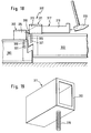
- Fig. 9 shows the interior of two abutting support and insulation elements 4 an embodiment in detail.
- the panels facing the interior 24 are undercut obliquely on their end faces, so that a composite or Press point on an edge results.
- This press point is preferably on the inside the roof structure 2 in front and serves as an additional seal against moisture in this area.
- a sealing element can also be formed in the space formed by the bevels to be ordered.
- a groove on the edge 46 of a support and insulation element 4 may be formed.
- a sealing cord can be placed in this groove or similar arrange, which provides an even better seal against moisture becomes.
- the visual appearance could be on the inside through training a dummy joint can be improved, as shown in Fig. 10.
- 11 is still an alternative sealing method is shown.
- a sealing lip is embedded in the plate 24, a dummy joint can also be formed.
- FIG. 12 shows a first embodiment of a dormer structure 101.
- the sectional view shown represents a portion of the dormer, in which a side part of the dormer is connected to the roof structure.
- the dormer structure 101 has a basic structure 102, which carries a roof covering 103 with battens and roof tiles. Furthermore, the Dormer structure 101 on a dormer 104, which in the figures only in Sub-areas is shown.
- the basic structure 102 has a plurality of arranged side by side and form-fitting or non-positively connected support and insulation elements 121 on, which are made up of a box-like frame and inside insulation exhibit.
- Such a basic construction 102 can correspond to the basic construction 1, as explained above with reference to FIGS. 1 to 11.
- the support and insulation element 121 has an edge element 122, in which one groove-like recess 123 is formed.
- This groove-like depression 123 is in cross section so triangular that it creates an inclined sliding surface.
- the dormer 104 generally has a side wall 141 on both sides, which in the connection area to the basic structure 102 each contains a side support 142.
- the side bracket 142 is formed with a spring-like projection 143.
- the groove-like depression 123 and the tongue-like projection 143 are here complementary, so that their inclined sliding surfaces on each other when mounting slide off and thus automatically establish a positive or non-positive connection.
- the side bracket 142 is in the Sidewall 141 integrated.
- the side wall 141 also has posts, one External formwork, a windbreak, an insulating layer and an inner lining.
- the side wall 141 can be prefabricated in an external workshop as well be built in the traditional manner on the side support 142.
- corner area between the side bracket 142 and the basic construction 102 can also be a metal panel or the like. for sealing against rain, snow and the like may be provided.
- FIG. 13 shows a further embodiment of a dormer structure according to the invention 101 '.
- a side bracket 142 ' attached to a side wall 141 'on the outside. This allows the side wall 141 ' be formed uniformly, as shown in Fig. 13. Then the constructive one Less effort for the production of the side wall.
- connection between the side carrier 142 or 142 'and the edge element 122 additionally by nails, screws or others Fasteners fixed.
- the sliding surfaces can also be provided with a lubricant, so that they slide better off each other.
- a sealing element can be arranged, which for an even better seal worries.
- FIG. 14 shows a further embodiment, according to which between the Basic structure 102 and the side support 142 an intermediate element 124 in shape a reinforcing bar with a width adapted to the application is.
- the intermediate element 124 is complementary to the on both sides Edge element 122 or to the side support 142 and is used, for example, for Reinforcement due to larger dormer loads.
- the basic construction 102 consists of a plurality of supporting and insulating elements 121 exists side by side with the help of such a groove-like depression and a corresponding spring-like projection can be connected, the case occur that on the dormer side not shown in the figures at the edge area there is a spring-like projection of the support and insulation element.
- the side support 142 of the dormer 104 can then be a differently designed intermediate element be arranged between the side support and the edge element, which offers a groove-like depression on both sides.
- a post 144 of the sidewall 141 about two oarlocks 145 to be fixed on the side member 142, which in particular a formation of the side wall on site, that is, in the case of a non-prefabricated side wall element is an advantage.
- the cut-outs for the oarlocks 145 can be used here are made in advance so that the post 144 is only placed on the side bracket 142 must be and if necessary is glued.
- the Basic structure 102 To connect the upper area of the dormer window to the roof structure, the Basic structure 102 also has an edge element in this area, which is provided with a groove-like depression. Complementarily designed upper connection elements the dormer can engage in this groove-like depression and so Establish a fast and automatic connection in this area too.
- the ceiling of a dormer window can also be attached to the be coupled to the upper edge regions of the side walls 141 or 141 '.
- At the bottom Connection area of the dormer can be a preferably insulated cross member be arranged, which in a tongue or groove of an underlying support or Insulating elements of the basic structure 102 engages and thus a stable coupling creates.
- the dormer window 104 could also be formed essentially completely in advance and are placed on the roof with a crane.
- the side straps with the side wall and the upper connecting elements of the dormer can then with relatively little effort taking into account the sloping roof in advance in a workshop getting produced.
- the entire dormer is due to the sliding surfaces Set down on the basic construction automatically slide into the correct position.
- the invention thus creates a dormer structure 101 or 101 'with a the roof covering 103 supporting basic structure 102 and a dormer window 104, which overlaps a recess in the basic structure 102.
- the Dormer 104 prefabricated side beams 142 and 142 'on a spring-like Have projection 143, which in a corresponding groove-like recess in the edge element 122 of the basic structure 102 engages.
- the groove-like recess 123 or the spring-like projection 143 formed triangular such that an inclined sliding surface is created, which when the side carrier 142 or 142 'is placed on the Basic construction 102 an automatic transfer to the desired position under Production of a positive or non-positive connection enables. So that with little time and Personnel expenditure a reliable and inexpensive production of a dormer 104 possible in any weather.
- a roof structure 201 has a basic structure 202 on, which carries a roof covering 203 and on the eaves side A rain gutter 204 is arranged at the end.
- the gutter 204 is over an eaves section 205 connected to an edge element 221 of the basic structure 202.
- the edge element 221 has a triangular groove 222.
- this groove 222 engages an analog projection 251 of eaves piece 205.
- the eaves piece 205 is such in the present embodiment according to FIG. 17 trapezoidal that it also has a contact surface for holding devices 241 Has gutter 204. In the present embodiment there is one eaves piece 205 is provided for each holding device 241. A height h of each eaves piece 205 is chosen so that the gutter 204 does not slope towards this downpipe shown has. Each eaves piece 205 therefore has a different one Height h up.
- the individual eaves pieces 205 are each screwed or nailed in advance to the holding device 241. Then they will Holding devices 241 with eaves pieces 205 each in their place on the eaves side Bring the end of the basic structure 202. The wedge-shaped projection 251 of the Eaves piece 205 is finally placed on the inclined sliding surface of the groove 222 and inserted into this. The eaves piece 205 is then fixed in the groove 222 by Nailing or screwing through the wedge-shaped projection 251. To the Sealing and closing the space between the top edge of the eaves section 205 or the holding device 241 and the upper edge of the basic structure 202 a plastic or elastic cementing 206 can be introduced.
- each eaves piece 205 has a different height h, the result is one correct arrangement of eaves 205 automatically a desired slope towards the downpipe.
- eaves piece 205 a single elongated piece can also be used Eaves piece, which is designed with varying heights.
- longer gutters 204 in which a downpipe is arranged in a central region, can also two or more longer eaves pieces can be provided, each with several holding devices Overlap 241.
- the groove in the basic construction can also be designed so that it that receives at least one eaves piece in a form-fitting manner. This is then in the side Insert groove. Additional means for fixation can then essentially be dispensed with become.
- the at least one eaves piece 205 can alternatively also first on the edge element 221 are fixed before a holding device 241 is fixed on the eaves piece 205 becomes.
- the at least one eaves piece 205 can have on the side facing away from the gutter 204 have a step into which a hook section of the holding devices 241 engages positively. This increases the Stability of the arrangement continues.
- the at least one eaves piece 205 can also be provided with one rectangular cross section. This would reduce the effort to produce the eaves piece 205. Then when assembling to ensure that each eaves piece 205 really completely in the analog trained Groove on the edge element 221 is inserted.
- the roof structure 201 according to the invention can also be particularly advantageous Use in conjunction with a support and insulation element as it does has been described with reference to FIGS. 1 to 11.
- This support and insulation element exists from a box-like frame, the peripheral edge of which has a spring-like projection or has a corresponding groove-like depression.
- the groove or the spring is so triangular that they have an inclined sliding surface. If the basic structure 202 of the roof structure 201 from such supporting and insulating elements a triangular groove 222 can be formed on the eaves side End of the basic construction 202. A special step in design this groove 222 is then no longer required. The effort for the production and assembly of the roof structure according to the invention is reduced further.
- the invention thus creates a roof structure 201 in which a rain gutter 204 quickly and easily to an eaves-side end of a basic structure 202 can be added, a desired gutter slope advantageously automatically due to the special design of the eaves piece according to the invention 205 results. If the at least one eaves piece 205 also in advance with the holding devices 241 of the gutter 204 is connected, the decrease from one Scaffolding or work required from the roof. A working person must therefore do not stay in this dangerous area for as long as it does in State of the art is the case and do not carry out such extensive work there.
- an assembly aid 301 is used for leveling a loose, self-arching plate 302 against a substrate, plate 302 engages a plate 303 already attached to the ground brought.
- the assembly aid 301 has two suspension devices 311 and 312, which each have a pipe section 313 and 314 and a rigidly connected threaded section 315 and 316 included.
- the pipe sections 313 and 314 are in cross section rectangular.
- threaded sleeves are provided in the plates 302 and 303 in advance 321 and 331 have been introduced, into which the threaded sections 315 and 316 are screwed in.
- the hooks 311 and 312 are used to align the loose plate anchored in alignment with one another at the edge region of the plates 302 and 303.
- a wedge element 317 of the assembly aid 301 is then by means of a hammer 304 through a suspension device 311 hammered into the other suspension device 312.
- the wedge element 317 has a wedge section 318 and a cuboid section 319 on. As shown in FIG. 18, the wedge section 318 also allows larger ones Bulges of the loose plate 302 thread the wedge element 317 into the second Hooking device 312.
- the wedge element 317 can then Example by means of a nose, as shown in Fig. 18, again from the hanging devices 311 and 312 are knocked out.
- the hangers 311 and 312 can then be unscrewed and then again at another point use.
- the hanging devices 311 and 312 can also have a different shape a rectangular cross-sectional shape.
- a rectangular cross-sectional shape comes one, for example polygonal or round design as well as a U-shaped shape, which on the two legs additional flanges for attachment to the Have plate 302 or 303.
- the anchoring of the hangers 311 and 312 on the plates 302 and 303 can also be done in other ways.
- here is a nailing or a Screwing on with wood screws without using threaded sleeves 321 or 331 possible.
- the assembly aid 301 according to the invention can also be used on metallic plates 302 and 303 are used, provided that the anchoring devices are anchored 311 and 312 are present.
- the assembly aid 301 can also be used to lay panels in any area. It is therefore not limited to use in the roof area.
- the assembly aid 301 is, however, suitable for supporting elements Roof construction, which are placed directly on purlins of the roof structure. Such support elements have been explained above with reference to FIGS. 1 to 11.
- the assembly aid 301 allows a particularly quick and reliable assembly this support elements even under the difficult conditions on a sloping roof.
- the invention thus creates an assembly aid 301 for leveling plate-shaped Body 302 and 303, in particular of supporting elements of a roof structure, wherein the mounting aid 301 has two hooking devices 311 and 312, which on edge regions of two adjacent plate-shaped bodies directed towards one another 302 and 303 can be anchored in alignment with one another, and a wedge element 317 through one hanging device 311 into the other hanging device 312 is insertable.
- This allows flatness even with curved or warped panels are produced without this requiring a great deal of effort or cumbersome measures would be required.
- This plan straightening can thus be done even with unfavorable ones Weather conditions and in difficult environments such as on a sloping roof run quickly.
Landscapes
- Engineering & Computer Science (AREA)
- Architecture (AREA)
- Civil Engineering (AREA)
- Structural Engineering (AREA)
- Physics & Mathematics (AREA)
- Electromagnetism (AREA)
- Mechanical Engineering (AREA)
- Roof Covering Using Slabs Or Stiff Sheets (AREA)
- Conveying And Assembling Of Building Elements In Situ (AREA)
Abstract
Description
Die vorliegende Erfindung betrifft eine Dachkonstruktion mit einer zumindest auf
einer Trauf- bzw. Fußpfette und/oder auf einer Mittelpfette und/oder auf einer
Firstpfette gelagerten, die Dacheindeckung tragenden Grundkonstruktion nach dem
Oberbegriff des Anspruchs 1 sowie ein Trag- und Dämmelement nach dem Oberbegriff
des Anspruchs 7. Weiter betrifft die Erfindung eine Dachgaubenkonstruktion nach dem
Oberbegriff des Anspruchs 9, eine Dachkonstruktion nach dem Oberbegriff des Anspruchs
13, ein Traufstück nach dem Oberbegriff des Anspruchs 16 und eine Montagehilfe
nach dem Oberbegriff des Anspruchs 18.The present invention relates to a roof structure with at least one
an eaves or foot purlin and / or on a middle purlin and / or on one
Ridge purlin supported basic construction according to the roof covering
Preamble of
Bislang werden Dächer für Gebäude, wie z.B. Wohnhäuser durch Verlegen von sogenannten Dachstühlen aus tragenden Balken und aufgelegten Sparten in ihrer Grundkonstruktion hergestellt. Zwischen die Sparten und/oder auf die Sparten wird dann eine Isolierung ein- bzw. aufgebracht. Nach neuerer Technologie wird die Isolierung als sogenannte Aufsparten-Dämmung montiert, die geringere Wärme- und Luftdurchlaßfugen hat. Die Sparten mit der ein- bzw. aufgebrachten Dachdämmung bilden bei diesen Dächern die Grundkonstruktion, welche dann die Dacheindeckung trägt.So far, roofs for buildings such as Residential houses by laying so-called roof trusses made of load-bearing beams and applied sections in their Basic construction manufactured. Between the divisions and / or the divisions then insert or apply insulation. According to newer technology, the insulation installed as so-called partition insulation, the lower heat and air passage joints Has. Form the divisions with the installed or applied roof insulation the basic construction of these roofs, which then supports the roof covering.
Nach Fertigstellung dieser Grundkonstruktion bzw. dieses Teilgewerkes, die je nach Ausführungsform obenauf mit einer Holzschalung und unten mit einer Verschreinerung abgeschlossen werden, wird sofort der Dachbelag meistens traditionsgemäß in Form von einer Ziegeldeckung auf längslaufender, d.h. in Sparrenlängsrichtung verlaufender Konterlattung und querlaufender Ziegellattung aufgebracht. Rechnet man die vor Ort hergestellten Arbeitsgänge zusammen, so läßt sich erkennen, daß ein wesentlicher Teil dieser Gewerke, nämlich das Verlegen der Balken bzw. Pfetten und das Auflegen der Sparren, das Ein- bzw. Aufbringen der Wärmedämmung, das Verlegen einer wasserableitenden Schicht, die sogenannte Unterdeckung oder das Unterdach eine ganze Reihe Arbeitsgänge mit sich bringen, die direkt an der Baustelle zu bewerkstelligen sind.After completion of this basic construction or this part of the trade, each According to the embodiment, on top with wooden formwork and below with a fence be completed, the roof covering is usually traditionally immediately in Form of a tile covering on a longitudinal, i.e. running in the longitudinal direction of the rafters Counter battens and transverse tile battens applied. If you do the math Site-made operations together, it can be seen that an essential Part of these trades, namely laying the beams or purlins and laying on the rafters, the introduction or application of thermal insulation, the laying of a water-draining Layer, the so-called under-roof or the sub-roof an entire Bring a series of work steps that can be carried out directly at the construction site are.
Die erfolgreiche Ausführung dieser Arbeitsgänge ist dabei immer von der Witterung abhängig und das zu erstellende Dach ist während seiner Erstellung wetterempfindlich. The successful execution of these operations is always dependent on the weather dependent and the roof to be created is weather sensitive during its creation.
Die zeitlich zuerst fertiggestellten Teilgewerke, wie z.B. das Unterdach in Form einer Folieneindeckung sind durch die nachfolgend auszuführenden Teilgewerke laufend der Gefahr einer Beschädigung ausgesetzt.The sub-trades completed first, e.g. the sub-roof in shape a foil covering are ongoing through the following sub-trades exposed to the risk of damage.
Die Unterschichten erfordern in aller Regel weitere örtliche Arbeiten durch Verkleiden mit Gipsplatten oder Verschreinerung mit Holzriemen, die dann vom nachfolgenden Handwerker, wie z.B. dem Gipser oder Schreiner auszuführen sind. Dies führt naturgemäß zu einer kosten- und zeitintensiven Dachkonstruktion.The lower layers usually require further local work by cladding with gypsum boards or wooden straps, which are then from the following Craftsmen such as the plasterer or carpenter are to be executed. this leads to naturally to a costly and time-consuming roof construction.
Diese Probleme traten auch bei einer Dachgaubenkonstruktion auf. Derartige Dachgauben werden derzeit in einer Vielzahl von einzelnen Arbeitsgängen vor Ort am Gebäudedach hergestellt. Hierzu werden im Seitenwandbereich der Dachgaube einzelne Pfosten aufgestellt und über Balken verbunden Die Dachgaube ist in den einigen Fällen zudem mit einem eigenen Dachstuhl versehen, der wiederum aus tragenden Balken und aufgelegten Sparten hergestellt ist. Ferner werden derartige Dachgauben sowohl im Seitenwandbereich als auch in ihrem Dachstuhl anschließend mit einer Isolierung, einer wasserableitenden Schicht und einer Innen- und Außenverkleidung versehen. All diese Arbeitsgänge sind dabei an der Dachschräge auszuführen, was das Arbeiten erschwert und zu einer gewissen Gefahr für die arbeitenden Personen führt. Ferner ist der Fortgang der Arbeiten bei schlechten Witterungsverhältnissen wesentlich erschwert. Die Herstellung einer derartigen Dachgaube ist daher umständlich, witterungsabhängig und zeitraubend.These problems also occurred with a dormer construction. Such Dormer windows are currently used in a large number of individual operations on site Building roof manufactured. For this purpose, some are in the side wall area of the dormer Posts set up and connected by beams The dormer window is in some cases also provided with its own roof truss, which in turn consists of load-bearing beams and is established. Furthermore, such dormers are both in Sidewall area as well as in your roof structure with insulation, one water-draining layer and an inner and outer cladding. All these Operations are carried out on the sloping roof, which makes working difficult and leads to a certain danger for the working people. Furthermore, the progress work in bad weather conditions significantly more difficult. The production Such a dormer window is therefore cumbersome, weather-dependent and time-consuming.
Ein weiterer Nachteil der bekannten Dachgaubenkonstruktionen liegt darin, daß die Anschlußstellen zwischen den Dachgaubenelementen und der Grundkonstruktion nur mit größerem Aufwand abgedichtet werden können. Hier ist zumeist eine Blechverblendung erforderlich, da die Verbindungsstellen an sich kaum eine Abdichtung herstellen.Another disadvantage of the known dormer structures is that the connection points between the dormer elements and the basic structure can only be sealed with great effort. Here is mostly a metal cladding required because the connection points hardly create a seal per se.
Ein weiteres Problem bei herkömmlichen Dachkonstruktionen liegt in der Befestigungsweise der Regenrinne. Bislang ist es üblich, Regenrinnen über Halterungen unmittelbar an eine Grundkonstruktion eines Dachaufbaus und insbesondere an den Sparren eines Dachstuhls zu befestigen. Hierzu muß ein Spengler entweder vom Dach oder von einem Gerüst aus auf die Sparten zugreifen können. Sofern bereits eine Dacheindeckung vorliegt, muß diese daher stellenweise entfernt werden. Die Halterungen werden dann gewöhnlich direkt auf die Sparren aufgenagelt. Um ein ausreichendes Gefälle der Regenrinne zum Fallrohr hin herstellen zu können, ist es erforderlich, daß jede einzelne Halterung individuell gebogen werden muß. Bei längeren Regenrinnen kann es zudem erforderlich sein, die Halterungen an einzelnen Sparren zu unterfüttern, oder die Sparrenhöhe durch Nachbearbeitung zu verringern. Dies ist dann der Fall, wenn der funktionelle Biegebereich einer Halterung nicht ausreicht, um ein ausreichendes Gefälle der Regenrinne herzustellen. Diese Feinarbeit der Gefälleeinstellung erfordert daher umfangreiche Tätigkeiten eines Spenglers in einem Bereich, der trotz Absperrungseinrichtungen und Gerüsten nicht ungefährlich für eine arbeitende Person ist.Another problem with conventional roof structures is how they are attached the gutter. So far, it has been common to drain gutters directly over brackets to a basic construction of a roof structure and in particular to the rafters to attach a roof truss. For this, a tinsmith must either from the roof or can access the divisions from a scaffold. If already a roof covering is present, it must therefore be removed in places. The mounts will be then usually nailed directly to the rafters. A sufficient gradient To be able to produce the gutter to the downpipe, it is necessary that each one Bracket must be bent individually. With longer gutters it can it may also be necessary to support the brackets on individual rafters, or the Reduce rafter height by post-processing. This is the case if the Functional bending range of a bracket is not sufficient to ensure a sufficient gradient the gutter. This fine adjustment of the incline therefore requires extensive activities of a plumber in an area that despite barriers and scaffolding is not safe for a working person.
Mittlerweile beginnt sich auf dem Markt die häufigere Verwendung von streifenbzw. rechteckförmigen Dachdämmplatten bzw. Dachdämmelementen zur Erstellung einer sogenannten Übersparrendämmschicht abzuzeichnen. Diese sind jedoch noch mit Fehlern behaftet. Ein Mangel solcher beispielsweise im wesentlichen aus Styropor aufgebauter Dachdämmplatten mit auf der Oberseite und der Unterseite aufgebrachter Deckschicht ist darin zu sehen, daß die Dachdämmplatten nebeneinander mit stumpfem Stoß verlegt werden, so daß von unten nach oben durchgängige Fugen und/oder in Firstrichtung über die gesamte Dachbreite durchlaufende Fugen entlang der stumpfen Stöße der Dämmplatten entstehen können. Diese werden dann, wenn überhaupt, lediglich verklebt oder verkittet. Damit kann aber auf Dauer keine ausreichende Dichtigkeit gegen Schlagregen oder von außen eindringende Feuchtigkeit gewährleistet werden. Ferner sind derlei Fingen in aller Regel nicht dauerhaft oder nur mit erheblichem Aufwand formelastisch abzudichten, so daß bleibende luftdurchlässige Ritzen in der Dachdämmung entstehen, die eine gute Wärmedämmung nicht mehr gewährleisten.Meanwhile, the more frequent use of stripes or rectangular roof insulation panels or roof insulation elements for creation a so-called over-rafter insulation layer. However, these are still with Buggy. A lack of such, for example, essentially made of polystyrene Roof insulation panels with applied on the top and bottom The top layer can be seen in the fact that the roof insulation panels side by side with blunt Butt are laid so that joints are continuous from bottom to top and / or in the ridge direction Continuous joints along the blunt joints across the entire roof width the insulation boards can arise. If at all, these will then only be glued or cemented. However, in the long term this cannot ensure adequate tightness Driving rain or moisture penetrating from outside can be guaranteed. Further Such catches are usually not permanent or only with considerable effort form-elastic seal so that permanent air-permeable cracks in the roof insulation arise that no longer guarantee good thermal insulation.
Bei einem anderen, neuerdings auf dem Markt befindlichen Dachdämmsystem werden bis zu 6 m lange, ca. 1,20 m breite streifenförmige Dachdämmelemente aus Styropor mit oberseitig aufgebrachter Spanplatte und unter- bzw. dachinnenseitig aufgebrachter Hartfaserdekorpaneele zwischen I-förmigen Sparren angeordnet. Dabei entstehen Fingen einerseits wegen der stumpf gegen die Seitenflanken der Sparren stoßenden Ränder der Dämmelemente und andererseits infolge der naturgemäß beim "Einfädeln" zwischen die I-förmigen Sparren der an Gurten an einem Kran hängenden Dachdämmelemente unvermeidbaren Beschädigungen deren Längsränder, sowie wegen der stumpf aneinander stoßenden oberen bzw. unteren Ränder. Zudem können die Dämmelelemente noch abschwinden. Abschließend erfolgt das Aufbringen der Lattung und der Ziegeldeckung. Die Herstellung einer preiswerten, gut wärmedämmenden Dachkonstruktion ist damit nicht möglich. Ein dauerhaft schlagwasserdichtes Dach sowie das dauerhafte Verhindern des Eindringens von Feuchtigkeit von außen ins Dach ist nicht gewährleistet.With another roof insulation system that has recently been launched up to 6 m long, approx. 1.20 m wide strip-shaped roof insulation elements made of polystyrene with chipboard on top and bottom or roof inside Hard fiber decorative panels arranged between I-shaped rafters. This creates Caught on the one hand because of the butt against the side flanks of the rafters Edges of the insulation elements and, on the other hand, due to the natural "threading" between the I-shaped rafters of the roof insulation elements hanging from belts on a crane unavoidable damage to their longitudinal edges, as well as because of butt-jointed upper and lower edges. In addition, the insulation elements still disappear. Finally, the battens and the Tile covering. The manufacture of an inexpensive, well-insulated roof structure is not possible with it. A permanently watertight roof and that permanent prevention of moisture from entering the roof is not guaranteed.
Die Verlegung plattenförmiger Körper gestaltet sich zudem insbesondere bei großformatigen Platten manchmal schwierig, da sich diese Verziehen können und somit Unebenheiten und Wölbungen auftreten. Dieses Problem ist insbesondere bei Holz- oder Holzfaserplatten bekannt. Als Gegenmaßnahme wird häufig ein Sperrholzaufbau gewählt, der jedoch auch nicht geeignet ist, um eine Wölbung in jedem Falle zu verhindern. Durch den Verzug derartiger Platten ist es aber bei deren Verlegung auf einem Untergrund bzw. einer Ankopplung an ein bereits vorliegendes Plattenelement erforderlich, daß die Wölbung mühsam unter einer gewissen Kraftaufbringung überwunden wird. Dies ist insbesondere bei Tragelementen für eine Dachkonstruktion nachteilig, da hier in einem ungünstigen Bereich an der Dachschräge gearbeitet werden muß. Liegen zudem schlechte Witterungsverhältnisse vor, so ist dies u.U. sogar besonders gefährlich und daher z.T. kaum ausführbar.The laying of plate-shaped bodies is also particularly useful large format plates sometimes difficult because they can warp and therefore Bumps and arches occur. This problem is particularly with wood or Fibreboard known. A plywood structure is often used as a countermeasure chosen, but is also not suitable to prevent curvature in any case. Due to the warpage of such panels, it is when laying them on one Underground or a coupling to an existing plate element is required, that the curvature was overcome with a certain amount of force becomes. This is disadvantageous in particular in the case of supporting elements for a roof structure, since here in an unfavorable area to work on the roof slope. Lie bad weather conditions, this may be even especially dangerous and therefore partly hardly feasible.
Das Dokument DE-OS 21 45 628 offenbart ein Trag- und Dämmelement für eine Dachkonstruktion, bei dem der äußere umfangsseitige Rand eines kastenartigen Rahmens eines ersten Trag- und Dämmelements einen Hakenabschnitt aufweist, der in einen darauf angepaßten Hakenabschnitt im benachbarten Trag- und Dämmelement eingreift. Hierzu ist der Hakenabschnitt des einen Trag- und Dämmelements lagegerecht über dem Hakenabschnitt des anderen Trag- und Dämmelements anzuordnen. In einer Ausführungsform können die Hakenabschnitte derart nachgiebig und mit Hinterschneidungen ausgebildet sein, daß das Eindrücken von Verdickungen der einen Randleiste in den Ausnehmungen der anderen Randleiste möglich wird, wodurch sich eine feste Verbindung zwischen zwei Platten ergibt. Hierzu müssen die benachbarten Trag- und Dämmelemente jedoch zuerst auf dem Dach exakt zueinander positioniert und festgelegt werden und es ist ein zusätzlicher Montageschritt zum Ineinanderdrücken der Hakenabschnitte erforderlich. Diese Konstruktion ist daher nachteilbehaftet, da ein großer Montageaufwand und exaktes Arbeiten erforderlich ist.The document DE-OS 21 45 628 discloses a support and insulation element for one Roof structure, in which the outer peripheral edge of a box-like frame of a first support and insulation element has a hook section, which in one adapted hook section engages in the adjacent support and insulation element. For this purpose, the hook section of the one supporting and insulating element is in the correct position to be placed over the hook section of the other support and insulation element. In a Embodiment, the hook sections can be so flexible and with undercuts be designed that the indentation of thickening of a sidebar in the recesses of the other sidebar is possible, creating a firm connection between two plates. For this, the neighboring supporting and However, insulation elements are first positioned and fixed exactly to each other on the roof and there is an additional assembly step for pressing the hook sections together required. This construction is therefore disadvantageous in that it requires a large amount of installation and precise work is required.
Der vorliegenden Erfindung liegt daher die Aufgabe zugrunde, unter Vermeidung der vorstehend diskutierten Mängel eine Dachkonstruktion derart weiterzubilden, daß eine wetterunempfindlichere Grundkonstruktion zur Verfügung gestellt wird, die beispielsweise mittels eines Baukranes bei fast jeder Witterung rasch verlegt werden kann. The present invention is therefore based on the object, while avoiding it of the defects discussed above to further develop a roof structure such that a weather-resistant basic construction is made available, for example can be quickly installed in almost any weather using a construction crane.
Diese Aufgabe wird durch die im Kennzeichnungsteil des Anspruchs 1 angegebenen
Maßnahmen gelöst.This object is achieved by the specified in the characterizing part of
Die erfindungsgemäße Dachkonstruktion ermöglicht erstmals eine kostengünstige, effiziente Dachkonstruktion. Die bei herkömmlichen Dachkonstruktionen bei der Herstellung der Grundkonstruktion bis kurz vor die Dacheindeckung und bis kurz vor die endgültige Fertigstellung der inneren Oberfläche anfallenden mannigfaltigen Arbeitsgänge, die an der Baustelle mit hoher Fehlergefährdung durchgeführt werden, können somit erstmals in die Werkstatt verlegt und damit zeitlich vorverlegt werden. Indem der Aufbau der Grundkonstruktion durch die Verwendung von witterungsunempfindlichen, vorgefertigten Trag- und Dämmelementen erfolgt, kann erstmals eine wetterunempfindlichere Grundkonstruktion erstellt werden. Dies geschieht vorteilhaft durch eine rasche, Arbeitskräfte sparende Verlegung der vorgefertigten Trag- und Dämmelemente mittels eines Baukrans, wobei dieser Arbeitschritt dann nahezu wetterunabhängig ist.The roof construction according to the invention enables for the first time an economical, efficient roof construction. The one with conventional roof constructions during manufacture the basic construction until just before the roof covering and until just before the final completion of the inner surface of various work processes which can be carried out at the construction site with a high risk of errors thus moved to the workshop for the first time and thus brought forward. By the Construction of the basic structure through the use of weather-insensitive, prefabricated support and insulation elements, can be a weather-insensitive for the first time Basic construction can be created. This is advantageously done by a rapid, Labor-saving laying of the prefabricated support and insulation elements by means of a construction crane, this step is then almost independent of the weather.
Dabei können die Trag- und Dämmelemente mittels einfachem Auf- und Ineinanderlegen auf die Pfetten aufgebracht werden, wobei nur ein Mann zum Einfahren und ggf. ein weiterer Mann zum Befestigen gebraucht wird. Dies sind deutlich weniger Arbeitskräfte, wie sie beim Verlegen von traditionellen, aus Sparren und Pfetten gebildeten Dachkonstruktionen benötigt werden.The support and insulation elements can be simply placed on and in one another be applied to the purlins, with only one man to drive in and if necessary, another man is needed for fastening. This is significantly fewer workers, like laying traditional rafters and purlins Roof structures are needed.
Erfindungsgemäß ist ein vorzugsweise von der Trauf- bzw. Fußpfette bis zur Firstpfette durchlaufendes Trag- und Dämmelement aus einem hohlkastenartigen Rahmen mit darin befindlichem Dämmstoff vorgesehen. Ein Trag- und Dämmelement wird mit dem benachbarten Trag- und Dämmelement mittels einer dreieck- bzw. hakenförmig ausgestalteten Außenkante formschlüßig verbunden, wobei sich das erste Trag- und Dämmelement in das nächstfolgende Trag- und Dämmelement einhängt. Beim Einhängen entsteht eine form- bzw. kraftschlüssige, dichte Verbindung, weil über die Schräge der Dreiecksnut die randseitige Feder des nachfolgend montierten Trag- und Dämmelements in die randseitige Nut das vormontierten Trag- und Dämmelements hineinrutscht. Diese Gleitschräge des erfindungsgemaßen, an der Nut bzw. an der Feder vorliegenden, Schrägfalzes ermöglicht so eine zuverlässige, exakte und schnelle Montage.According to the invention is preferably from the eaves or foot purlin to the Continuous ridge purlin supporting and insulating element from a hollow box-like frame provided with insulation. A support and insulation element is with the neighboring support and insulation element by means of a triangular or hook-shaped designed outer edge positively connected, the first support and Hooks the insulation element into the next support and insulation element. When hanging there is a positive or non-positive, tight connection because of the slope the triangular groove is the edge-side tongue of the support and insulation element installed below the pre-assembled support and insulation element slips into the groove on the edge. This slide slope of the present invention, which is present on the groove or on the tongue, Angled folds thus enable reliable, exact and quick installation.
Durch entsprechende Vorbereitung dieser Fuge, vorzugsweise durch einen Anstrich mit einem Gleitmittel wie z.B. Schmierseife kann dieser Gleiteffekt erheblich verbessert werden. Vorteilhaft ist es dann nicht notwendig, diese die Verkeilung bzw. Verspannung herbeiführende Verbindung bei der Herstellung des hohlkastenartigen Rahmens zu hobeln. Es genügt beispielsweise, wenn diese Fuge mit einer schnelllaufenden Kreissäge im Schrägschnitt bei geringer Schubgeschwindigkeit für eine glatte Schnittfläche hergestellt wird. Das komplette Trag- und Dämmelement erfüllt die bauphysikalischen und statischen Forderungen bereits deshalb, weil durch die hohlkastenförmige Formulierung quasi ein Hohlträger entsteht, der vorteilhaft folgende bauphysikalische Konsistenzen ausweist:By appropriate preparation of this joint, preferably by painting with a lubricant such as Soft soap can significantly affect this sliding effect be improved. It is then advantageously not necessary to wedge or Tension-producing connection in the manufacture of the hollow box-like Planing frame. It is sufficient, for example, if this joint has a fast-running Circular saw in diagonal cut at low thrust for a smooth Cut surface is produced. The complete support and insulation element fulfills the building physics and static requirements already because of the hollow box-shaped Formulation quasi a hollow beam arises, which advantageously follows the following building physics Consistencies shows:
Die an der unteren Seite des hohlkastenförmigen Rahmens montierte, zum Dachinnenraum weisende Platte ist vorzugsweise relativ dicht und stark dampfbremsend. Die darüber folgend zwischen den Schenkeln des Rahmens im erzeugten Hohlkasten angeordnete Wärmedämmung kann aus den verschiedensten Dämmstoffen hergestellt werden. Bevorzugt finden Dämmstoffe aus Mineralfasern oder Dämmplatten aus Zellulosepaketen Anwendung.The one mounted on the lower side of the hollow box-shaped frame, towards the roof interior facing plate is preferably relatively dense and strong vapor retardant. The following between the legs of the frame in the hollow box created Arranged thermal insulation can be made from a wide variety of insulation materials become. Insulation materials made of mineral fibers or insulation panels made of cellulose packages are preferred Application.
Eine gegebenenfalls über der Dämmschicht liegende Luftschicht bildet ein weiteres Dämmelement. In diesem Bereich kann eine schmale Holzplatte bzw. Holzleiste auf den Schenkeln des Rahmens aufgebracht werden. Darüber ist eine vorzugsweise etwas weichere, obere Deckplatte angeordnet, die einen geringeren Dampfdiffusionswiderstand hat, wie die untere Platte. Diese ist wasserabweisend behandelt, also z.B. silikonisiert, getränkt oder mit einer wasserabweisenden Schicht versehen. Die Holzleiste kann aus besonders tragfähigem Holz gewählt werden, quasi wie die obere Hälfte eines Trägers, während die untere Hälfte eines solchen gedachten Trägers durch die harte Unterschale dargestellt wird. Dies kann dann angezeigt sein, wenn die weichere bzw. dampfdurchlässigere Oberschicht bzw. obere Platte keine so hohe statische Tragfähigkeit aufweist und dennoch größere Spannweiten erzielt werden sollen. Der Einbau einer Dampfbremse bzw. -sperre z.B. auf der Innenseite ist zudem ebenso möglich, wie die Verstärkung der Unterschicht durch eine Tapezierung u.ä..A layer of air that may lie above the insulation layer forms another Insulation element. In this area, a narrow wooden plate or wooden strip can be found be applied to the legs of the frame. One is preferably something above that softer, upper cover plate arranged, which has a lower vapor diffusion resistance like the bottom plate. This is treated to be water-repellent, e.g. siliconized, impregnated or provided with a water-repellent layer. The wooden bar can selected from particularly stable wood, quasi like the upper half of a beam, while the lower half of such an imaginary beam through the hard lower shell is pictured. This can be indicated if the softer or more vapor permeable Upper layer or upper plate does not have such a high static load-bearing capacity and still larger spans should be achieved. The installation of a Vapor barrier or barrier e.g. on the inside is also possible, like the Reinforcement of the lower layer by wallpapering etc.
Die wasserabweisend behandelte Oberfläche bzw. die wasserabweisende Beschichtung soll zumindest zeitweiligen Nässelasten widerstehen. Sie braucht jedoch nicht eine dauerhafte Dachhaut darstellen. Über dieser Ebene ist es nun möglich, in einfachster Form, jede schnelle Dachbelegung mit einem geeigneten Dachbelag und auch das herkömmliche Ziegeldach aufzubringen. Selbst die Herstellung von Flachdächern ist damit möglich.The water-repellent treated surface or the water-repellent coating should at least withstand temporary wet loads. However, it needs do not represent a permanent roof membrane. Over this level it is now possible in the simplest Shape, any quick roofing with a suitable roofing and also to apply the conventional tile roof. Even the manufacture of flat roofs is possible with it.
Der Seitenverbund kann, damit über die Fugen der aneinander anstoßenden und ineinander eingreifenden Trag- und Dämmelemente kein Wasser einzieht, mit einer vorzugsweise im Nutgrund angeordneten Dichtung versehen werden. Als Dichtung wird hierfür vorzugsweise eine feine, dichtende, selbstausdehnende Schnur verwendet. Damit wird auch die Luftdichte erheblich verbessert.The side bond can so that over the joints of the abutting and interlocking support and insulation elements do not draw in water, preferably with one seal arranged in the groove base. As a seal a fine, sealing, self-expanding cord is preferably used for this. In order to the air density is also significantly improved.
Auf diese Art und Weise wird es erstmals möglich, ein Haus innerhalb weniger Stunden vollständig einzudecken, nachdem die gesamten vorbereitenden Arbeiten in der Werkstatt stattgefunden haben.This way it becomes possible for the first time to build a house within a few Hours to fully stock up after all the preparatory work in the Workshop took place.
Die erfindungsgemäße Dachkonstruktion unterscheidet sich in vorteilhafter Weise beispielsweise durch folgende Merkmale gegenüber einer herkömmlichen Sparrenkonstruktion:The roof construction according to the invention differs in an advantageous manner for example by the following features compared to a conventional rafter construction:
Es werden nicht mehr Einzelteile verlegt, sondern es werden fertig vormontierte Trag- und Dämmelemente aus einem hohlkastenartigen Rahmen mit darin befindlichem Dämmstoff verlegt, wobei der hohlkastenartige Rahmen als statisches Element bekannt und damit bereits im voraus exakt berechenbar ist. Dabei kann der Rahmen zwar aus Balken oder Sparten aufgebaut sein. Vorzugsweise werden die Seitenteile bzw. Schenkel des Rahmens jedoch aus zwei oder drei verleimten Schichten gebildet. Dadurch entsteht ein gegen Verziehen resistenter, besonders stabiler Rahmen. Dies steht im Gegensatz zum traditionellen Sparren aus Vollholz, der sich verwinden kann.Individual parts are no longer installed, but are pre-assembled Support and insulation elements made of a hollow box-like frame with an inside Insulation laid, the hollow box-like frame known as a static element and is therefore precisely predictable in advance. The frame can be made Bars or divisions. Preferably the side parts or legs However, the frame is made up of two or three glued layers. This creates a warp resistant, particularly stable frame. This is in conflict for traditional solid wood rafters that can twist.
Das efindungsgemäße Trag- und Dämmelement hat keine Kerven mehr (Kerben), mit denen der Sparren auf die Pfetten aufgekämmt wird, sondern es weist vorzugsweise angesetzte, horizontal verlaufende leistenartige Nocken bzw. Warzenleisten auf, die statisch berechnet und dementsprechend befestigt sind und die auf einer korrespondierenden auf der Pfette angebrachten Gegenwarze aufliegen oder in entsprechende Kerben eingreifen. Die am Trag- und Dämmelement angebrachten Warzenleisten können auch einteilig am Rahmen angeformt sein.The support and insulation element according to the invention no longer has any knobs (notches), with which the rafters are combed onto the purlins, but it preferably points attached, horizontally running strip-like cams or wart strips on the statically calculated and fixed accordingly and that on a corresponding Place the nipple on the purlin or in corresponding notches intervention. The wart strips attached to the support and insulation element can also be integrally formed on the frame.
Dies hat den Vorteil, daß die erfindungsgemäßen Trag- und Dämmelemente mit relativ Kleinen Schrauben oder Blechstreifen auf den Pfetten bzw. auf den daran befestigen Warzenleisten angeschraubt werden können. Die bis zu 30 cm langen Sparrennägel, die mit der Axt eingetrieben werden, sind damit Vergangenheit. Dabei werden die Warzenleisten einerseits am Trag- und Dämmelement und andererseits auf der Fuß-, Mittel- oder Firstpfette mit hochwertigem Leim fixiert und bei Bedarf zusätzlich verschraubt. Alternativ werden Kerben in den Pfetten vorgesehen in denen die Warzenleisten einrasten. Auf diese Art und Weise wird die Dachkonstruktion vorteilhaft in weit präziserer Art wie bisher fixiert.This has the advantage that the support and insulation elements according to the invention Attach relatively small screws or sheet metal strips to the purlins or on them Wart bars can be screwed on. The up to 30 cm long rafter nails, those that are driven in with the ax are a thing of the past. The wart strips on the one hand on the support and insulation element and on the other hand on the foot, middle or Ridge purlin fixed with high-quality glue and additionally screwed if necessary. Alternatively, notches are provided in the purlins in which the wart strips snap into place. In this way, the roof structure becomes advantageous in far more precise Fixed as before.
Außerdem wird bei Dächern ohne Durchbrüche sofort eine durchgängig wasserableitende Dachdeckung erzielt. Anstelle der üblichen Ziegeleindeckung kann auch eine von oben aufzubringende entsprechende passende Metallverkleidung problemlos vorgesehen werden.In addition, roofs without breakthroughs immediately become completely water-draining Achieved roofing. Instead of the usual brick covering, you can also a suitable metal cladding to be applied from above without any problems be provided.
Als äußere Abmessung für das Trag- und Dämmelement hat sich eine Größe von ca. 1,25 m x 6 m bei einer Höhe von ca 140 bis 220 mm als besonders vorteilhaft erwiesen. Diese Größenordnung ist auch leicht in mittelständischen Handwerksbetrieben wie z.B. einer Schreinerei und/oder Zimmerei herstellbar.The outer dimension for the support and insulation element has a size of about 1.25 mx 6 m with a height of about 140 to 220 mm has proven to be particularly advantageous. This size is also easy in medium-sized craft businesses such as e.g. a joinery and / or carpentry.
Dabei ist selbstverständlich das Breitenmaß als auch das Längenmaß nicht fix begrenzt. Letzteres richtet sich vorzugsweise nach der Haustiefe. Es können daher auch sehr tiefe Dächer hergestellt werden. Dächer mit einer Tiefe von 6 bis 8 m oder Dächer mit einer Tiefe von 8 bis 14 m wie auch Dächer mit einer Tiefe von 12 bis 18 m sind mit der erfindungsgemäßen Dachkonstruktion problemlos realisierbar. Üblicherweise soll das erfindungsgemäße Trag- und Dämmelelement zumindest eine Tiefe von etwa 6 m überbrücken, was dann einer Haustiefe von etwa 11 bis 12 m entspräche, die im üblichen Wohnbau für gewöhnlich erforderlich sind.Of course, the width dimension and the length dimension are not permanently limited. The latter preferably depends on the depth of the house. It can therefore also very deep roofs are made. Roofs with a depth of 6 to 8 m or roofs with a depth of 8 to 14 m as well as roofs with a depth of 12 to 18 m can be easily realized with the roof construction according to the invention. Usually the support and insulation element according to the invention should be at least a depth of approximately Bridge 6 m, which would then correspond to a house depth of about 11 to 12 m, which in the usual housing are usually required.
Selbstverständlich werden auf dieser Grundidee fußend weitere Varianten möglich sein. Beispielsweise kann der hohlkastenartige Rahmen über die Mittelpfette hochragen, so daß keine Firstpfette benötigt wird und anstatt dessen die firstseitigen Ränder zweier aneinander stoßender Trag- und Dämmelemente gegeneinanderlaufend miteinander verbunden werden. Dabei wird von unten ein beispielsweise dreieckiges Element bzw. ein Dreiecksdammelement angeschraubt, das von oben mit Stange und Hutprofil versehen werden kann.Of course, further variants are possible based on this basic idea be. For example, the hollow box-like frame can protrude above the middle purlin, so that no ridge purlin is needed and instead the ridge-side edges of two abutting support and insulation elements connected to each other in a mutually opposing manner become. From below, for example, a triangular element or a Screwed on triangular dam element, which is provided with a rod and hat profile from above can be.
Die synergistische Verbindung zwischen einem kastenförmigen Körper, der einerseits sämtliche Funktionen der Statik und andererseits die Dämmung aufnimmt und darüber hinaus einen Dichtschluß zwischen den nebeneinander liegenden Trag- und Dämmelementen infolge seiner Formulierung erzwingt, ermöglicht erstmals eine dauerhaft Schlagwasserdichte Dachkonstruktion bei der ebenso auf Dauer das unerwünschte Eindringen von Feuchtigkeit von außen ins Dach verhindert ist. The synergistic connection between a box-shaped body, on the one hand all functions of statics and on the other hand absorbs the insulation and above In addition, a tight seal between the supporting and insulating elements lying next to each other enforced due to its wording, allows for the first time permanent Impact-proof roof construction, which in the long term also prevents unwanted intrusion is prevented from moisture from outside into the roof.
Sollte trotzdem durch Unachtsamkeit oder Verletzung der Oberfläche Feuchtigkeit in ein Trag- und Dämmelement eindringen, so kann dieses durch nachträgliches Einbringen von wieder verschließbaren Bohrungen vom Dachinnenraum her oben und unten in das betroffene Trag- und Dämmelement kontrolliert getrocknet werden.Should be caused by carelessness or damage to the surface penetrate into a support and insulation element, this can be done by retrofitting of reclosable holes from the roof interior above and below be dried in a controlled manner in the affected support and insulation element.
Die Trag- und Dämmelemente können zur Aussteifung sowohl in ihrer Längsrichtung als auch in ihrer Querrichtung zwischen dem hohlkastenförmigen Rahmen mit versteifenden Mittelsprossen versehen werden.The support and insulation elements can be used for stiffening both in their longitudinal direction as well as in their transverse direction between the hollow box-shaped frame stiffening middle rungs are provided.
Durch den gegenseitigen Eingriff der Ränder benachbarter Trag- und Dämmelemente entsteht ein hoher Verbund in der Gesamtfläche, der die Dachfläche zu einer steifen Platte werden läßt. Dies ist hinsichtlich des resultierenden großen Widerstands gegen Windkräfte ein wertvoller Vorteil, der mit einem herkömmlichen Sparrendach nicht so leicht zu leisten ist.Through the mutual engagement of the edges of adjacent support and insulation elements creates a high bond in the total area, which makes the roof area rigid Plate. This is in view of the resulting great resistance to Wind power is a valuable advantage that is not possible with a conventional rafter roof is so easy to do.
Die Befestigung wird nicht mehr wie früher durch die Dämmschicht und den Sparren mit einer Langschraube oder einem Langnagel erzeugt, sondern über die warzenförmigen Auflagen an der Untererseite des Trag- und Dämmelements und auf der Pfettenobererseite. Die Qualität der Dachkonstruktion kann somit nach der Verlegung der Trag- und Dämmelemente von unten her überprüft werden, was eine deutliche Reduzierung der Verletzungsgefahr mit sich bringt. Es muß bei der Verlegung selbst kein Mann mehr auf dem Dach herum klettern, wodurch erstmals eine auch bei nassem Wetter ungefährliche Montage ermöglicht wird die zudem noch deutlich rascher erledigt werden kann, als bislang.The fastening is no longer as before by the insulation layer and the Rafters created with a long screw or an long nail, but over the wart-shaped Conditions on the lower side of the support and insulation element and on the Purlin top. The quality of the roof structure can thus be after laying the support and insulation elements are checked from below, which is a significant reduction the risk of injury. There is no need for the laying itself Man climbing around more on the roof, making it the first time even when wet Weather-proof installation enables it to be done much faster can be than before.
Die erfindungsgemäße Dachkonstruktion beinhaltet darüber hinaus infolge der in einer Art Serienfertigung zu realisierenden Herstellung des Trag- und Dämmelements erhebliche kosteneinsparende Rationalisierungsvorteile. Da sich bei 1,25 m breiten Teilen Dachliegefenster genauso wie stehende Gaupen in das Maßgefüge problemlos einbringen lassen, bestehen auch für komplexere Projektierungen keine Hindernisse. Darüber hinaus können die erfindungsgemäßen Trag- und Dämmelemente in vereinfachter Form auch für große Dachüberstände genutzt werden.The roof structure according to the invention also includes due to the in a kind of series production of the support and insulation element considerable cost-saving rationalization advantages. Because there are 1.25 m wide parts Insert roof windows as well as standing dormers into the dimensional structure without any problems there are no obstacles, even for more complex configurations. About that In addition, the supporting and insulating elements according to the invention can be simplified Shape can also be used for large roof overhangs.
Neben einer vorzugsweise als Dichtschnur ausgebildeten Dichtung im Nutgrund zum Dichten zweier aneinander stoßender Trag- und Dämmelemente kann zur Verbesserung des Seitenverbundes eine weitere Dichtung im Bereich des Stosses der Kanten aneinandergrenzender oberen Platten vorgesehen werden. Dabei können deren Seitenkanten schräg von oben außen nach unten innen angefaßt sein, so daß zwei aneinandergrenzende Kanten oberer Platten einen dreiecks- oder trapezförmigen schmalen Spalt bilden, der von der Dichtung, beispielsweise von einer selbstausdehpenden Dichtschnur voll ausgefüllt wird. Für eine Verbesserung der Dichtung im Bereich des Stirnverbundes kann die nach unten weisende Kante der oberen Platte eines Trag- und Dämmelements von unten her angeschrägt sein und über den unteren Rand des Rahmens hinausstehen, so daß sie auf der oberen Platte des darunter angeordneten Trag- und Dämmelements im Kantenbereich zu liegen kommt, wobei diese obere Platte im Kantenbereich korrespondierend angeschrägt ist, so daß eine stetig nach unten weisende Wasserabführung gewährleistet wird. Ferner kann zur kostensparenden Verbesserung der Abdichtung zwischen den Pfetten und den Trag- und Dämmelemente eine zwischen den Warzenleisten angeordnete Dichtung, vorzugsweise wiederum eine Dichtschnur vorgesehen werden.In addition to a seal in the groove base, which is preferably designed as a sealing cord for sealing two abutting support and insulation elements can improve another seal in the area of the joint of the edges adjacent upper plates can be provided. In doing so, their side edges be held diagonally from the top outside down to the inside, so that two adjacent Edges of upper plates a triangular or trapezoidal narrow gap form that of the seal, for example of a self-expanding sealing cord is fully filled. For an improvement of the seal in the area of the forehead joint can the downward-facing edge of the top plate of a support and insulation element beveled from below and protrude beyond the lower edge of the frame, so that they are on the upper plate of the support and insulation element arranged below Edge area comes to rest, this upper plate corresponding in the edge area is chamfered so that a constantly downward water drainage is guaranteed becomes. Furthermore, between cost-saving improvement of the seal the purlins and the supporting and insulating elements one between the wart strips arranged seal, preferably again a sealing cord can be provided.
Je nach Tiefe der kastenförmigen Konstruktion können moderne Beleuchtungskörper in die Dachfläche eingelassen werden oder wenig raumverbrauchende Leitungsführungen untergebracht werden. Dabei ist weiter von Vorteil, daß derlei Gestaltungsvarianten infolge der Herstellung des Trag- und Dämmelements in der Werkstatt und nicht auf der Baustelle wesentlich genauer und eleganter hergestellt werden können, wobei mannigfaltige andere Gestaltungsvarianten hinsichtlich des Designs der Innenseite des Trag- und Dämmelements denkbar sind.Depending on the depth of the box-shaped construction, modern lighting fixtures can are embedded in the roof surface or little space-consuming cable routing be accommodated. It is also advantageous that such design variants as a result of the production of the supporting and insulating element in the workshop and not can be manufactured on the construction site much more precisely and elegantly, whereby diverse other design variants with regard to the design of the inside of the Support and insulation elements are conceivable.
Da sich die unterseitigen Warzen an jeder Stelle an dem kastenartigen Rahmen anbringen bzw. befestigen lassen und auch zwischen die einzelnen Trag- und Dämmelemente analog ausgeformte einzelne Vollträger einlegen lassen, die ihrerseits horizontale Zangen aufnehmen können, sind diverse Entwicklungsmöglichkeiten gegeben.Because the warts on the underside are everywhere on the box-like frame can be attached or fastened and also between the individual support and insulation elements have individual full girders of the same shape inserted, which in turn are horizontal There are various development options available for picking up pliers.
Weitere vorteilhafte Weiterbildungen der Erfindung sind Gegenstand der Unteransprüche.Further advantageous developments of the invention are the subject of the dependent claims.
Gemäß einem weiteren Aspekt der vorliegenden Erfindung wird eine Dachgaubenkonstruktion mit den Merkmalen des Anspruches 9 bereitgestellt. Diese löst die erfindungsgemäße Aufgabe ebenfalls, da sie mit einfachen Mitteln schnell und bei fast jeder Witterung aufgestellt werden kann.In accordance with another aspect of the present invention, a dormer structure is provided provided with the features of claim 9. This solves the invention This is also a task, as it can be done quickly and almost with simple means can be set up in any weather.
Die erfindungsgemäße Dachgauberkonstruktion ermöglicht somit erstmals eine kostengünstige und effiziente Bauweise aufgrund der vorgefertigten Seitenträger. Diese können mittels des dort ausgestalteten federartigen Vorsprungs zuverlässig in entsprechend ausgebildete Randelemente der Grundkonstruktion eingreifen, wodurch in einem Zuge eine stabile Aufstellung eines Seitenträgers möglich ist. Im Gegensatz zum Stand der Technik wird der Dachaufbau erfindungsgemäß so vorbereitet, daß eine Vorfertigung der Seitenträger in einer Werkstatt erfolgen kann und die Seitenträger auf dem Dach nur noch in die Grundkonstruktion eingesetzt werden müssen. Dieses Einsetzen kann dabei je nach den Gegebenheiten durch einen Kran oder manuell erfolgen.The roof slider construction according to the invention thus enables for the first time Cost-effective and efficient design due to the prefabricated side carriers. This can reliably by means of the spring-like projection designed there trained edge elements of the basic structure engage, which in one A stable installation of a side carrier is possible. In contrast to the stand The technology of the roof structure according to the invention is prepared so that a prefabrication the side carrier can be done in a workshop and the side carrier on the Roof only need to be inserted into the basic structure. This onset can be done by crane or manually, depending on the circumstances.
Damit laßt sich eine rasche Verlegung mit wenigen Arbeitskräften erzielen, welche zudem aufgrund der Einfachheit des Vorgangs auch bei ungünstigen Witterungsverhältnissen möglich ist.This allows a quick transfer with few workers to achieve which also because of the simplicity of the process, even in unfavorable weather conditions is possible.
Von weiterem Vorteil ist hierbei, daß die nutartige Vertiefung bzw. der federartige Vorsprung eine schräge Gleitfläche aufweisend dreieckig ausgebildet sind. Dadurch sind die Seitenträger lediglich mit den Randelementen der Grundkonstruktion in Eingriff zu bringen, wobei dann selbsttätig ein Hineinrutschen des Seitenträgers erfolgt, so daß die Verbindung automatisch in der richtigen Lage zu liegen kommt. Damit ist eine formschlüssige und aufgrund des Eigengewichts der Seitenträger auch eine kraftschlüssige Verbindung zwischen den Bauelementen hergestellt.Another advantage is that the groove-like recess or the spring-like Projection have an oblique sliding surface are triangular. Thereby the side supports are only engaged with the edge elements of the basic construction bring, then then automatically slipping into the side carrier, so that the connection is automatically in the correct position. So that's one positive and due to the weight of the side straps also a non-positive Connection between the components made.
Zudem ergibt sich aufgrund der besonderen Ausgestaltung der Nut-Feder-Verbindung eine dichte Verbindungsweise in diesem Bereich.In addition, due to the special design of the tongue and groove connection a dense connection in this area.
Ein weiterer Vorteil der vorliegenden Erfindung liegt darin, daß die Gefahr von Montagefehlem wesentlich verringert ist. Durch die vorgefertigten Elemente und die vorgegebene Geometrie an den Verbindungsstellen sind kaum Fehler bei der Montage möglich.Another advantage of the present invention is that the risk of Assembly errors is significantly reduced. Through the prefabricated elements and the Predefined geometry at the connection points are hardly any errors during assembly possible.
Dadurch, daß der Seitenträger in einer Seitenwand integriert ist, ergibt sich ein sehr stabiler und dennoch schlanker Aufbau der Seitenwand, wodurch der verfügbare Raum in der Aussparung der Grundkonstruktion in großem Maße als Nutzraum für die Dachgaube verwendet werden kann.The fact that the side carrier is integrated in a side wall results in a very stable and yet slim construction of the side wall, which makes the available Space in the recess of the basic construction to a large extent as usable space for the Dormer can be used.
Von weiterem Vorteil ist es, wenn der Seitenträger mit dem federartigen Vorsprung außenseitig an der Seitenwand befestigt ist. Diese Alternativbauweise erlaubt es, die Seitenwand der Gaube als durchgängige Wand z.B. mit bereits integrierter Isolierung vorzufertigen. Dadurch können zudem bessere und gleichmäßigere Dämmeffekte in diesem Bereich erzielt werden. It is a further advantage if the side carrier with the spring-like projection is attached to the outside of the side wall. This alternative design allows the side wall of the dormer as a continuous wall e.g. with already integrated insulation prefabricate. This also allows better and more uniform insulation effects can be achieved in this area.
Wenn das Randelement der Grundkonstruktion im Bereich der Seitenträger ein Zwischenelement aufweist, das auf einer Seite mit der Grundkonstruktion zusammenwirkt und auf der anderen Seite eine nutartige Vertiefung für den federartigen Vorsprung im Seitenträger der Dachgaube aufweist, kann vorteilhafterweise bei größerer Gaubenlast eine Art Verstärkungsbalken eingezogen werden. Darüber hinaus kann dieses Zwischenelement genutzt werden, um beidseits der Dachgaube eine nutartige Vertiefung bereitzustellen, auch wenn das Randelement der Grundkonstruktion auf einer Seite einen federartigen Vorsprung anbieten würde. Dadurch kann die erfindungsgemäße Dachgaubenkonstruktion auf einfache Weise in eine Dachkonstruktion integriert werden, bei der Trag- und Dämmelemente nebeneinander angeordnet und über entsprechende dreieckige Nuten und Federn form- bzw. kraftschlüssig miteinander verbunden sind.If the edge element of the basic construction in the area of the side girders Has intermediate element that cooperates on one side with the basic structure and on the other side a groove-like depression for the tongue-like projection in the side member of the dormer can advantageously be larger Dormer load a kind of reinforcement beam are pulled in. In addition, this The intermediate element can be used to create a groove-like depression on both sides of the dormer window provide, even if the edge element of the basic structure on a Side would offer a feathery head start. This allows the invention Roof dormer construction easily integrated into a roof construction are arranged in the support and insulation elements next to each other and via appropriate triangular grooves and tongues are positively or non-positively connected are.
Von weiterem Vorteil ist es, wenn das Randelement der Grundkonstruktion im oberen Bereich der Dachgaube wenigstens einen Anschlußteil aufweist, das mit einer nutartigen Vertiefung versehen ist, in welche ein federartiger Vorsprung von oberen Abschlußelementen der Dachgaube eingreift. Damit läßt sich auch im oberen Abschlußbereich der Dachgaube zum Gebäudedach eine schnelle Montage mit einfachen Mitteln herstellen. Durch die dort ebenfalls vorliegende dreieckige Nut- bzw. Federverbindung mit einer schrägen Gleitfläche kann mit geringem Arbeitsaufwand eine besonders gute Anbindung hergestellt werden. Damit wäre es auch möglich, die Dachgaube im wesentlichen vollständig vorzufertigen und als ganzes mittels einem Kran auf dem Dach aufsetzen und über die Gleitflächen in die vorbestimmte Lage zu bringen. Der Aufwand zur Herstellung der Dachgaube und insbesondere eine mögliche Gefährdung für arbeitende Personen kann damit wesentlich verringert werden.It is a further advantage if the edge element of the basic construction in upper area of the dormer window has at least one connecting part, which with a groove-like recess is provided, in which a tongue-like projection from the top Closing elements of the dormer engages. It can also be used in the upper end area the dormer to the building roof a quick assembly with simple means produce. Due to the triangular tongue and groove connection also present there with an inclined sliding surface can be a particularly good one with little effort Connection can be made. This would also allow the dormer to be essentially completely prefabricated and put on the roof as a whole using a crane and bring it into the predetermined position via the sliding surfaces. The effort for Production of the dormer window and, in particular, a possible hazard for working people People can be significantly reduced.
Vorteilhaft ist ferner, wenn die Dachgaube wenigstens einen Pfosten aufweist, welcher über vorzugsweise zwei Dollen am Seitenträger befestigt ist. Dann ist auch ein traditioneller Aufbau der Dachgaube vor Ort auf der Basis der Seitenträger möglich, wobei der Pfosten über die Dollen zuverlässig auf den Seitenträgern aufsitzt und in seiner Lage fixiert ist.It is also advantageous if the dormer window has at least one post, which is attached to the side member via preferably two oarlocks. Then there is also one traditional construction of the dormer window possible on the basis of the side beams, the post sits securely over the oarlocks on the side beams and in his Location is fixed.
Alternativ können die Seitenwände mit den Seitenträgern und/oder die oberen Anschlußelemente auch als Fertigteil vorgefertigt sein, wodurch sich eine sehr schnelle und einfache Montage der Dachgaube vor Ort erreichen läßt. Die Wandfertigteile können hierbei ohne weiteres in einer Werkstatt hergestellt werden. Dies erlaubt eine weitere Reduzierung der Montagezeiten und des Montageaufwands auf der Baustelle.Alternatively, the side walls with the side supports and / or the upper connection elements also be prefabricated as a finished part, which results in a very fast and easy installation of the dormer on site. The prefabricated wall parts can are easily manufactured in a workshop. This allows one more Reduction of assembly times and assembly effort on the construction site.
Gemäß einem weiteren Aspekt der vorliegenden Erfindung wird eine Dachkonstruktion mit den Merkmalen des Anspruches 13 bereitgestellt, welche eine Grundkonstruktion, die eine Dacheindeckung trägt, und eine Regenrinne aufweist. Auch diese Bauweise löst die gestellte Aufgabe, da hierdurch der Montage- und Zeitaufwand zur funktionsgerechten Anbringung einer Regenrinne wesentlich verringert werden kann.According to another aspect of the present invention, a roof structure provided with the features of claim 13, which is a basic construction, which has a roof covering and a gutter. This too Design solves the task, as this means that the assembly and time required Functional installation of a gutter can be significantly reduced.
Erfindungsgemäß genügt es daher vorteilhafterweise die Regenrinne mit dem wenigstens
einen Traufstück in die Nut am traufseitigen Ende der Grundkonstruktion einzufügen.
Durch dieses 
In vorteilhafter Weise bietet die erfindungsgemäße Dachkonstruktion erstmals die Möglichkeit, ein Regenrinnengefälle mit einfachen Mitteln vorab festzulegen. Da das wenigstens eine Traufstück hier aufgrund seiner Gestalt eine entsprechende Voreinstellung vornimmt, ist vorteilhafterweise keine individuelle Anpassung jeder einzelnen Regenrinnenhalterung erforderlich. Der damit verbundene Arbeitsaufwand entfällt somit. Insbesondere kann die Anpassung des wenigstens einen Traufstücks in einer Werkstatt o.ä. erfolgen, was die Arbeit wesentlich vereinfacht und wirtschaftlicher ist.The roof construction according to the invention advantageously offers the first time Possibility to determine a gutter slope in advance using simple means. Since that at least one eaves piece here has a corresponding presetting due to its shape is advantageously not an individual adjustment of each gutter bracket required. The work involved is therefore eliminated. In particular, the adaptation of the at least one eaves piece in a workshop or similar take place, which simplifies the work considerably and is more economical.
Weiter ist von Vorteil, daß sich eine arbeitende Person somit weitaus weniger lang auf dem Gerüst oder auf dem Dach aufhalten muß, wodurch eine wesentlich geringere Gefährdung für den Menschen gegeben ist. Zudem verringert sich der Arbeitsaufwand für einen Spengler oder dgl. vor Ort an der Traufe deutlich.Another advantage is that a working person is thus much less long on the scaffolding or on the roof, which means a much smaller one There is a danger to humans. The workload is also reduced for a tinsmith or the like on site at the eaves clearly.
Ferner läßt sich das wenigstens eine Traufstück aufgrund seiner Gestaltung gut in die analog ausgebildete Nut in der Grundkonstruktion einfügen und mit einfachen Mitteln wie zum Beispiel einer Nagel- oder Schraubverbindung daran anfügen. Da auch die Dachrinnenhalterungen zum Beispiel durch eine Nagel- oder Schraubverbindung an das wenigstens eine Traufstück anfügbar sind, kann ein Spengler erfindungsgemäß auf die Verwendung zusätzlicher Werkzeuge wie zum Beispiel ein Stemmeisen zum Bearbeiten des Sparrens und ähnliches bei der Arbeit an der Traufe verzichten. Die erfindungsgemäße Dachkonstruktion läßt somit eine sehr schnelle und mühelose Montage einer Regenrinne zu.Furthermore, due to its design, the at least one eaves piece can be well in insert the analog groove into the basic construction and with simple means such as a nail or screw connection. Since that too Gutter brackets, for example, by a nail or screw connection to the at least one eaves piece can be attached, a tinsmith according to the invention Use of additional tools such as a chisel for machining of rafters and the like when working on the eaves. The invention Roof construction thus allows a very quick and effortless installation of a gutter to.
Von weiterem Vorteil ist es, wenn die Nut derart dreieckig ausgebildet ist, daß eine schräge Fläche vorliegt, und das Traufstück im Querschnitt einen entsprechend dreieckig ausgebildeten Vorsprung aufweist. Die schräge Fläche der Nut kann dann als Gleitfläche für das Einführen des Traufstücks dienen, wodurch die Montage des wenigstens einen Traufstücks an das traufseitige Ende der Grundkonstruktion weiter erleichtert wird. Zudem kann dadurch der Schwerpunkt des Traufstücks so gelegt werden, daß es von selbst oder mit geringerem Halteaufwand in der Nut verbleibt, bis eine Fixierung vorgenommen ist. Vorteilhaft ist hierbei ferner, daß durch die dreieckige Ausgestaltung der Nut eine bessere Anbindung an das traufseitige Ende der Grundkonstruktion möglich ist, da Nägel oder Schrauben einen größeren Bereich des Traufstücks durchgreifen, wenn sie durch den entstehenden keilförmigen Vorsprung hindurchgeführt werden.It is a further advantage if the groove is triangular in shape that a oblique surface is present, and the eaves piece in cross-section is correspondingly triangular trained projection. The inclined surface of the groove can then be used as Sliding surface for the insertion of the eaves serve, whereby the assembly of the at least a eaves piece on the eaves-side end of the basic construction is further facilitated becomes. In addition, the center of gravity of the eaves piece can be placed so that it remains in the groove by itself or with less effort until it is fixed is made. It is also advantageous that the triangular shape the groove allows a better connection to the eaves-side end of the basic construction is because nails or screws penetrate a larger area of the eaves piece, if they are passed through the resulting wedge-shaped projection.
Wenn das wenigstens eine Traufstück an der Regenrinne vormontiert ist, kann es zusammen mit dieser am traufseitigen Ende der Grundkonstruktion angeordnet werden, wodurch sich die Montageschritte in diesem gefährlichen Bereich weiter verringern. Bei dieser Ausgestaltungsweise ist lediglich noch eine Befestigung des wenigstens einen Traufstücks an der Grundkonstruktion erforderlich, wobei sich das Dachrinnengefälle selbsttätig einstellt. Der Arbeitsaufwand im Bereich der Traufe verringert sich dadurch weiter.If the at least one eaves piece is pre-assembled on the gutter, it can be arranged together with this on the eaves-side end of the basic structure, which further reduces the assembly steps in this dangerous area. At this embodiment is only an attachment of the at least one Eaves piece required on the basic construction, with the gutter slope automatically sets. This reduces the workload in the area of the eaves further.
Indem ein Traufstück vorliegt, welches sich in Längsrichtung der Regenrinne erstreckt und eine variierende Höhe aufweist, kann die Basis für jede Halteeinrichtung der Regenrinne festgesetzt werden, ohne daß Fehler bei der Herstellung des Regenrinnengefälles möglich sind. Aufgrund seiner Gestalt läßt das Traufstück dann keine falsche Anordnungsweise zu. Die Montage vereinfacht sich dadurch weiter.By having an eaves piece that extends in the longitudinal direction of the gutter and has a varying height, the base for each holding device Gutter can be fixed without errors in the manufacture of the gutter slope possible are. Due to its shape, the eaves piece does not leave any wrong arrangement to. This further simplifies assembly.
Alternativ können auch mehrere Traufstücke vorliegen, welche mit unterschiedlichen Höhen ausgebildet und jeweils einer Halterung der Regenrinne zugeordnet sind. Dadurch kann der Materialaufwand deutlich verringert werden. Gleichzeitig verringert sich auch das Gewicht der Anordnung, so daß diese noch einfacher montierbar ist.Alternatively, there can also be several eaves pieces with different ones Heights formed and each associated with a bracket of the gutter. This can significantly reduce the cost of materials. Reduced at the same time also the weight of the arrangement, so that it is even easier to assemble.
Gemäß einem weiteren Aspekt der vorliegenden Erfindung wird ein Traufstück
zur Anbindung einer Regenrinne an eine Grundkonstruktion einer Dachkonstruktion
bereitgestellt, welches die Aufgabe ebenfalls löst und die kennzeichnenden Merkmale
des Anspruches 16 aufweist.According to another aspect of the present invention, an eaves piece
for connecting a rain gutter to a basic structure of a roof structure
provided, which also solves the task and the characteristic features
of
Mit diesem erfindungsgemäßen Traufstück lassen sich die oben ausführlich diskutierten Vorteile erzielen. Zudem sind die entsprechenden vorteilhaften Weiterbildungen möglich.With this eaves piece according to the invention, those discussed in detail above can be discussed Get benefits. In addition, the corresponding advantageous developments possible.
Gemäß einem weiteren Aspekt der vorliegenden Erfindung wird eine Montagehilfe mit den Merkmalen des Anspruches 18 bereitgestellt. Auch diese dient zur Lösung der erfindungsgemäßen Aufgabe, da hiermit plattenförmige Körper mit einfachen Mitteln plangerichtet werden können, wenn dies erforderlich ist.According to a further aspect of the present invention, an assembly aid provided with the features of claim 18. This also serves as a solution the object of the invention, since hereby plate-like body with simple means can be planned if necessary.
Die erfindungsgemäße Montagehilfe zeichnet sich durch eine sehr einfache Bauweise aus, wobei dennoch eine sehr hohe Funktionalität erzielbar ist. Die Einhängevorrichtungen sind lediglich an den plattenförmigen Körpern zu verankern, wobei durch das Keilelement beim Einfügen eine gute Kraftübertragung erzielt wird. Das Eintreiben des Keils kann dabei durch ein herkömmliches Werkzeug wie zum Beispiel einen Hammer erfolgen.The assembly aid according to the invention is characterized by a very simple construction from, but a very high functionality can still be achieved. The hangers are only to be anchored to the plate-shaped bodies, with the wedge element when inserting a good power transmission is achieved. The driving in the wedge can be done by a conventional tool such as a Hammer done.
Aufgrund der Keilgestalt richtet sich die Platte unter Überwindung von deren Vorspannung nach und nach plan aus und kann anschließend auf der Unterkonstruktion oder am benachbarten Plattenelement befestigt werden. Das lösen der Montagehilfe kann dann ebenfalls mit sehr einfachen Mitteln erfolgen. Hierzu ist lediglich das Keilelement wieder aus den Einhängevorrichtungen herauszuführen. Die Einhängevorrichtungen können dann entfernt werden.Due to the wedge shape, the plate aligns itself by overcoming it Preload gradually out and then on the substructure or attached to the adjacent plate element. That loosen the assembly aid can then also be done with very simple means. For this is only the wedge element out of the hooks again. The hangers can then be removed.
Aufgrund der einfachen Bedienbarkeit der erfindungsgemäßen Montagehilfe kann diese auch zum Beispiel im Bereich einer Dachschräge verwendet werden, ohne daß hierdurch eine wesentliche Gefahr für eine arbeitende Person entsteht. Zudem lassen sich Platten in der erfindungsgemäßen Weise sehr schnell plan ausrichten.Because of the ease of use of the assembly aid according to the invention these can also be used, for example, in the area of a sloping roof without this creates a significant danger for a working person. Also leave plates align themselves very quickly in the manner according to the invention.
Wenn die Einhängevorrichtungen rohrförmig sind und insbesondere einen rechteckigen Querschnitt aufweisen, wird zudem vorteilhafterweise eine gute Führung für das entsprechend auszubildende Keilelement geschaffen. Ein Verkanten des Keilelements oder ein Verdrehen, wie dies zum Beispiel bei einer runden Ausgestaltung der Einhängevorrichtung möglich wäre, kann so noch wirksamer vermieden werden. If the hanging devices are tubular and in particular a rectangular one Have cross-section, will also advantageously good guidance for created the wedge element to be trained accordingly. Tilting of the wedge element or twisting, as is the case, for example, with a round design of the Hanging device would be possible can be avoided even more effectively.
Dadurch, daß das Keilelement einen Keilabschnitt und eine Quaderabschnitt aufweist, kann es sowohl zum Heranziehen der Platte in die gewünschte Ebene mittels der Keilschräge als auch zum Halten in diesem Bereich durch den quaderförmigen Abschnitt genutzt werden. Die Belastung des Keilabschnitts im völlig eingefügten Zustand durch die Vorspannung der gewölbten Platte kann so vom Quaderabschnitt zuverlässig aufgefangen werden, ohne daß der Keilabschnitt weiter beansprucht wäre. Dadurch erhöht sich die Lebensdauer der erfindungsgemäßen Montagehilfe weiter.Because the wedge element has a wedge section and a cuboid section, can be used to pull the plate into the desired level using the Wedge bevel as well as for holding in this area through the cuboid section be used. The load on the wedge section when fully inserted by pre-stressing the arched plate can reliably from the cuboid section be collected without the wedge portion being further stressed. This increases the service life of the assembly aid according to the invention continues.
Von weiterem Vorteil ist es, wenn die Einhängevorrichtungen mittels einer Verschraubung in den plattenförmigen Körpern verankert sind. Dann können sie zuverlässig daran angekoppelt werden und zudem ist eine einfache Demontage nach dem Befestigen der gewölbten Platte am Untergrund möglich. Die Einhängevorrichtungen der Montagehilfe können somit oftmals genutzt werden.It is a further advantage if the hanging devices by means of a screw connection are anchored in the plate-shaped bodies. Then they can be reliable can be coupled to it and is also easy to disassemble after fastening the curved plate on the surface possible. The hooks of the assembly aid can often be used.
Dadurch, daß die plattenförmigen Körper Gewindehülsen aufweisen, vereinfacht sich die Montage der Einhängevorrichtungen wesentlich. Da die Verankerungsposition am plattenförmigen Körper damit vorbestimmt und auch vorbereitet ist, kann das Planrichten noch wesentlich schneller ausgeführt werden.Characterized in that the plate-shaped body have threaded sleeves, simplified the mounting of the hangers is essential. Because the anchor position on the plate-shaped body is predetermined and prepared, the planing can run even faster.
Die Erfindung wird nachstehend anhand der Beschreibung von Ausführungsbeispielen unter Bezugnahme auf die Zeichnung näher erläutert. Es zeigen:
- Fig. 1
- einen Querschnitt durch eine erste Ausführungsform der Grundkonstruktion einer erfindungsgemäßen Dachkonstruktion;
- Fig. 2
- eine Draufsicht auf die in Fig. 1 dargestellte erfindungsgemäße Dachkonstruktion;
- Fig. 3
- vergrößerte schematische Darstellungen einer in Fig. 1 und 2 dargestellten Dachkonstruktion in den Bereichen um eine Firstpfette, um eine Fußpfette und um eine Mittelpfette;
- Fig. 4
- eine vergrößerte schematische Darstellung des Seitenverbundes zweier erfindungsgemäßer Trag- und Dämmelemente;
- Fig. 5
- eine aufgebrochene Draufsicht auf eine mögliche Ausführungsform eines erfindungsgemäßen Trag- und Dämmelement;
- Fig. 6
- eine vergrößerte schematische Darstellung einer Alternative zu der in Fig. 3 und 4 gezeigten Ausführungsform;
- Fig. 7
- eine vergrößerte schematische Darstellung einer Alternative zu der in Fig. 3 gezeigten Ausführungsform;
- Fig. 8
- eine vergrößerte schematische Darstellung einer anderen Alternative zu der in Fig. 3 gezeigten Ausführungsform;
- Fig. 9
- eine vergrößerte schematische Darstellung einer weiteren Ausführungsform des Seitenverbundes zweier erfindungsgemäßer Trag- und Dämmelemente;
- Fig. 10
- eine vergrößerte schematische Darstellung einer anderen Ausführungsform des Seitenverbundes zweier erfindungsgemäßer Trag- und Dämmelemente;
- Fig. 11
- eine vergrößerte schematische Darstellung noch einer weiteren Ausführungsform des Seitenverbundes zweier erfindungsgemäßer Trag- und Dämmelemente;
- Fig. 12
- eine Schnittansicht eines seitlichen Teilbereiches einer Dachgauberkonstruktion gemäß einer ersten Ausführungsform;
- Fig. 13
- eine Schnittansicht einer Dachgaubenkonstruktion gemäß einer zweiten Ausführungsform;
- Fig. 14
- eine Detailansicht mit einem Zwischenelement;
- Fig. 15
- eine Seitenansicht eines Details der Dachgaubenkonstruktion;
- Fig. 16
- einen Querschnitt durch ein traufseitiges Ende einer Dachkonstruktion;
- Fig. 17
- ein erfindungsgemäßes Traufstück;
- Fig. 18
- einen Anwendungsfall einer erfindungsgemäßen Montagehilfe; und
- Fig. 19
- eine Einhängevorrichtung der erfindungsgemäßen Montagehilfe.
- Fig. 1
- a cross section through a first embodiment of the basic structure of a roof structure according to the invention;
- Fig. 2
- a plan view of the roof structure according to the invention shown in Figure 1;
- Fig. 3
- 1 and 2 enlarged schematic representations of a roof structure in the areas around a ridge purlin, a foot purlin and a middle purlin;
- Fig. 4
- an enlarged schematic representation of the side composite of two support and insulation elements according to the invention;
- Fig. 5
- a broken plan view of a possible embodiment of a support and insulation element according to the invention;
- Fig. 6
- an enlarged schematic representation of an alternative to the embodiment shown in Figs. 3 and 4;
- Fig. 7
- an enlarged schematic representation of an alternative to the embodiment shown in Fig. 3;
- Fig. 8
- an enlarged schematic representation of another alternative to the embodiment shown in Fig. 3;
- Fig. 9
- an enlarged schematic representation of a further embodiment of the side composite of two supporting and insulating elements according to the invention;
- Fig. 10
- an enlarged schematic representation of another embodiment of the side composite of two support and insulation elements according to the invention;
- Fig. 11
- an enlarged schematic representation of yet another embodiment of the side composite of two support and insulation elements according to the invention;
- Fig. 12
- a sectional view of a side portion of a roof raster construction according to a first embodiment;
- Fig. 13
- a sectional view of a dormer structure according to a second embodiment;
- Fig. 14
- a detailed view with an intermediate element;
- Fig. 15
- a side view of a detail of the dormer structure;
- Fig. 16
- a cross section through an eaves-side end of a roof structure;
- Fig. 17
- an eaves piece according to the invention;
- Fig. 18
- an application of an assembly aid according to the invention; and
- Fig. 19
- a suspension device of the assembly aid according to the invention.
Eine erste Ausführungsform einer erfindungsgemäßen Dachkonstruktion ist in den Fig. 1 bis 11 dargestellt.A first embodiment of a roof structure according to the invention is in the 1 to 11 are shown.
Wie in Fig. 1 im Querschnitt einer Ausführungsform der Grundkonstruktion 1 einer
erfindungsgemäßen Dachkonstruktion 2 gut erkennbar ist, sind zwei Reihen von
Trag- und Dämmelementen 4 übereinander angeordnet. Dies ist in der Regel bei Dächern
mit einer Tiefe TD über 12 m der Fall. Die Trag- und Dämmelemente 4 sind reihenweise
nebeneinander angeordnet, was im Schnitt allerdings nicht erkennbar ist. Die
Trag- und Dämmelemente 4 stützen sich im Bereich ihres unteren Endes 6 auf der Fuß- bzw.
Traufpfette 8 ab. Je nach Tiefe TD des Daches und Länge LTDE der Trag- und
Dämmelemente stützen sich diese zusätzlich im Bereich ihres oberen Endes 10 entweder
auf der Firstpfette 12 oder der Mittelpfette 14 ab. Sie können sich jedoch auch frei
auskragend im Bereich ihres oberen Endes 10 gegen das obere Ende eines auf der gegenüberliegenden
Dachhälfte angeordneten Trag- und Dämmpelements 4 abstützten,
wobei sich die Trag- und Dämmelemente 4 dann in der Regel im Bereich ihrer oberen
Hälfte auf der Mittelpfette 14 abstützen. Dies ist nicht näher dargestellt.As can be clearly seen in FIG. 1 in cross section of an embodiment of the
Die aus Trag- und Dämmelementen 4 erstellte Grundkonstruktion 1 trägt die
Dacheindeckung 16, die herkömmlich als Ziegeleindeckung oder auch andersartig, z.B.
als Aluminiumblecheindeckung ausgebildet sein kann, wie dies aus Fig. 2 hervorgeht.The
Das Trag- und Dämmelement 4 ist beispielsweise, wie in Fig. 3 oder 4 dargestellt,
als Rahmen 20 aus vier Holzbalken bzw. Sparren 22 gebildet. Diese Holzbalken 22
können ca. 30 mm bis 60 mm stark sein und eine Höhe von ca. 140 bis 220 mm aufweisen.
Es ist aber auch jedes andere Maß, denkbar, je nach zu bewältigender Dachlast,
Windlast und Schneelast entsprechend den Vorgaben der statischen Berechnungen. Die
Sparren bzw. Schenkel 22 des Rahmens 20 können auch aus mehrfach verleimten Holzschichten
aufgebaut sein. Hierbei können auch Leisten Verwendung finden, so daß im
Prinzip jegliche Stärke und Höhe möglich ist. Vernünftigerweise wird man die Maße
beispielsweise in 10 mm Schritten abstufen. Abgesehen davon kann auch jede andere
Rahmenkonstruktion vorgesehen werden. Aus gewichts- und fertigungstechnischen
Gründen dürften Aluminiumprofile eine gute Alternative darstellen. An der Unterseite
ist eine Platte 24 beispielsweise aus Holz angebracht. Deren zum Dachinnenraum gewandte
Oberfläche kann beispielsweise mit Echtholzpaneelen, Hartfaser-Holzdekorpaneelen
oder dergleichen anderen auch tapezierfähigen Innenverkleidungen
25 beschichtet sein. Die Oberseite wird beispielsweise durch eine Spanplatte 26, die
wasserabweisend behandelt worden ist, also beispielsweise mit einer wasserabweisenden
Deckschicht 27 versehen sein kann, verschlossen. Die Unter- und Oberseite kann
jedoch auch beidemale mit wasserdichten Spanplatten beplankt sein. Dazwischen befindet
sich das Dämmmaterial 28, wobei dieses als Mineralwolledämmfilz bzw. Mineralwolledämmplatte
oder dergleichen gut wärmedämmenden Dämmstoffen ausgebildet
sein kann. Dabei kann sich die Auswahl des Dämmstoffes problemlos nach den bauphysikalischen
Berechnungen und den Wünschen des Bauherren richten. Ferner ist die Anordnung
einer Dampfsperre bzw. -bremse möglich.The support and
Die in Fig. 2 gezeigte Draufsicht auf die in Fig. 1 dargestellte erfindungsgemäße
Dachkonstruktion 2 läßt den modulartigen Aufbau erkennen. Über einer ersten, unteren
Reihe 30 von Trag- und Dämmelementen 4 ist bei dem dargestellten Dachtyp wenigstens
eine weitere, obere Reihe 32 von Trag- und Dämmelementen 4 angeordnet. Dies
ist in der Regel dann erforderlich, wenn Dachtiefen TD im Bereich von 12 bis 18 m realisiert
werden sollen. Dachtiefen TD von 6 bis 8 m können noch mit einer Reihe von
Trag- und Dämmelementen 4 realisiert werden. Bei Dachtiefen TD von 8 bis 14m ist
dies auch noch möglich. Jedoch sollte je nach Anwendungsfall mit Rücksicht auf die
Baustatik entschieden werden, ob nicht doch die Anordnung von zwei oder mehr Reihen
von Trag- und Dämmelementen 4 angzeigt ist.The plan view shown in FIG. 2 on the
Wie aus Fig. 2 erkennbar, schließen die jeweilig benachbarten Trag- und Dämmelemente
4 nahtlos aneinander an, so daß zwischen ihnen keine wasserdurchlässigen
Fugen oder Spalte entstehen können. Durch die teilweise aufgebrochene Darstellung in
Fig. 5 ist das im Trag- und Dämmelement 4 befindliche Dämmmaterial 28 erkennbar.As can be seen from Fig. 2, the respective adjacent support and insulation elements close
4 seamlessly to each other so that no water-permeable between them
Joints or gaps can arise. Due to the partially broken representation in
5, the insulating
In Fig. 3 ist eine vergrößerte Darstellungen einer in Fig. 1 und 2 dargestellten
Dachkonstruktion 2 in den Bereichen um eine Firstpfette 12, um eine Fußpfette 8 und
um eine Mittelpfette 14 schematisch veranschaulicht. Das Trag- und Dämmelement 4
weist an seiner Unterseite bzw. an seiner unteren Beplankung bzw. an der unteren
Spanplatte 24 eine erste Warzenleiste 34 auf, mit der sich das Trag- und Dämmelement
4 gegen die Fußpfette 8 und/oder gegen eine an der Fußpfette angebrachte korrespondierende
Warzenleiste 36 abstüzt oder in eine entsprechende Kerbe 37 in der Fußpfette 8
einrastet. In ähnlicher Weise ist das Trag- und Dämmelement 4 über wenigstens eine
weitere an seiner Unterseite angebrachte Warzenleiste 38 gegen die Mittelpfette 14
und/oder eine an der Mittelpfette befestigten Warzenleiste 40 oder korrespondierende
Kerbe gelagert. Die Abstützung des Trag- und Dämmelements 4 erfolgt in dessen oberen
Bereich gegen die Firstpfette 12 und/oder gegen eine an dieser befestigten Warzenleiste
42 oder einen Dreickesdamm in analoger Weise, ggf. direkt oder durch eine weitere
an der Unterseite angebrachte Warzenleiste 44. Die am oberen Ende des Trag- und
Dämmelements befestigte Warzenleiste 38 oder 44 kann auch integral an dem den oberen
Rahmenabschnitt ausbildenden Balken bzw. Sparren angeformt oder ausgebildet
sein.3 is an enlarged view of one shown in FIGS. 1 and 2
In einer vergrößerten schematischen Darstellung des Seitenverbundes zweier erfindungsgemäßer
Trag- und Dämmelemente 4 ist in Fig. 4 die hakenfalzartige Ausgestaltung
in Form von dreiecksartigen Vertiefungen bzw. Erhöhungen des äußeren, umlaufenden
Randes 46 des Trag- und Dämmelements 4 erkennbar. Eine Feder 48 am
Rand 46 des einen Trag- und Dämmelements 4 greift in eine Nut 50 im Rand 46 des
benachbarten Trag- und Dämmelements 4. Dabei sind Nut 50 und Feder 48 zueinander
korrespondierend ausgebildet und weisen eine schräge Gleitfläche 52 auf. Damit ist gewährleistet,
daß beim Aneinanderfügen zweier Trag- und Dämmelemente 4 diese sich
beispielsweise allein durch ihr Eigengewicht miteinander dichtschließend verbinden.
Zur weiteren Erhöhung der Dichtigkeit der Verbindung kann im Nutgrund eine Dichtschnur
54 vorgesehen werden.In an enlarged schematic representation of the side composite of two according to the invention
The supporting and
In Fig. 5 ist in einer teilweise aufgebrochenen Draufsicht eine mögliche Ausführungsform
eines erfindungsgemäßen Trag- und Dämmelements 4 näher dargestellt. Wie
bereits auch zum Teil aus Fig. 1 erkennbar, ist das Trag- und Dämmelement 4 beispielsweise
als Rahmen aus vier Holzbalken bzw. Sparren 22 gebildet, die beispielsweise
aus mehrfach verleimten Schichten aufgebaut sein können. Deren Stärke richtet sich
in erster Linie nach den zu bewältigenden Lasten. Andere Rahmenkonstruktion, wie
z.B. ein Rahmen aus Aluminiumprofilen, sind ebenso denkbar. Die Unterseite ist durch
eine Platte 24 beispielsweise aus Holz zum Dachinnenraum hin abgeschlossen. Die
Platte 24 ist vorzugsweise relativ dicht und stark dampfbremsend. Deren zum Dachinnenraum
gewandte Oberfläche kann mit Innenverkleidungen beschichtet sein. Zudem ist
die Auflage einer Dampfsperte außen oder innen am Trag- und Dämmelement 4 möglich.5 shows a possible embodiment in a partially broken top view
of a support and
Die Oberseite bildet beispielsweise eine wasserabweisend behandelte Spanplatte
26, deren Dampfdiffusionswiderstand geringer ist, als derjenige der unteren Platte 24.
Durch die wasserabweisende Behandlung der Oberfläche der Platte 26 bzw. ihr selbst,
kann ggf. auf die Aufbringung einer Schicht aus Dach- bzw. Teerpappe auf die wetterseitige
Fläche verzichtet werden.The top forms, for example, a water-
Im Innenraum 56 des Trag- und Dämmelements 4 befindet sich das Dämmmaterial
28. Hierzu kann ein Mineralwolledämmfilz oder auch Mineralwolledämmplatten
verwendet werden. Genaus gut sind andere Dämmstoffe verwendbar. Zur Aussteilung
des Trag- und Dämmelements können sowohl in Längsrichtung als auch in Querrichtung
angeordnete Mittelsprossen 58 bzw. 60 eingefügt werden. Deren Anzahl richtet
sich nach der gewünschten Aussteifung und der zu erwartenden Lasten.The insulation material is located in the interior 56 of the support and
Wie aus Fig. 6 ersichtlich findet im Nutgrund die vorstehend beschriebene, vorzugsweise
als Dichtschnur 54 ausgebildete Dichtung zum Dichten zweier aneinander
stoßender Trag- und Dämmelemente 4 Verwendung. Zur verbesserten Abdichtung des
Seitenverbundes kann eine weitere Dichtung 62 im Bereich des Stosses der Kanten aneinandergrenzender
oberen Platten 26 vorgesehen werden. Dabei können deren Seitenkanten
64 schräg von oben außen nach unten innen angefast sein, so daß zwei aneinandergrenzende
Kanten 64 oberer Platten 26 einen vorbestimmten dreiecks- oder trapez- bzw.
schwalbenschwanzförmigen schmalen Spalt 66 bilden, der von der Dichtung 62,
beispielsweise von einer selbstausdehnenden Dichtschnur voll ausgefüllt wird.As can be seen from FIG. 6, the groove base described is preferably the one described above
formed as a
Für eine Verbesserung der Dichtung im Bereich des Stirnverbundes kann, wie in
Fig. 7 gezeigt, die nach unten weisende Kante 68 der oberen Platte 26 eines Trag- und
Dämmelements 4 von unten her angeschrägt sein und über den unteren Rand 70 des
Rahmens 20 hinausstehen, so daß sie auf der oberen Platte 26 des darunter angeordneten
Trag- und Dämmelements 4 im Kantenbereich 72 zu liegen kommt. Diese obere Platte
ist im Kantenbereich 72 korrespondierend angeschrägt, so daß eine stetig nach unten
weisende Wasserabführung gewährleistet wird.To improve the seal in the area of the forehead joint, as in
Fig. 7 shown, the
Ferner kann, wie in Fig. 8 dargestellt, zur kostensparenden Verbesserung der Abdichtung
zwischen den Pfetten 8,12 bzw. 14 und den Trag- und Dämmelementen 4 eine
zwischen den Warzenleisten 34, 38 bzw. 42 angeordnete Dichtung 74, vorzugsweise
wiederum eine Dichtschnur vorgesehen werden.Furthermore, as shown in Fig. 8, for cost-saving improvement of the seal
between the
Fig. 9 zeigt den Innenbereich zweier aneinander stoßender Trag- und Dämmelemente
4 einer Ausführungsform im Detail. Die zum Innenraum hin vorliegenden Platten
24 sind hier an ihren Stirnseiten schräg hinterschnitten, so daß sich eine Verbund- bzw.
Preß-Stelle an einer Kante ergibt. Diese Preß-Stelle liegt vorzugsweise an der Innenseite
der Dachkonstruktion 2 vor und dient als zusätzliche Abdichtung gegen Feuchtigkeit in
diesem Bereich. In dem durch die Schrägen gebildeten Raum kann zudem ein Dichtelement
angeordnet werden.Fig. 9 shows the interior of two abutting support and
Gemäß der Darstellung in Fig. 10 kann alternativ auch eine Nut am Rand 46 von
einem Trag- und Dämmelement 4 ausgebildet sein. In dieser Nut läßt sich eine Dichtschnur
o.ä. anordnen, wodurch eine noch bessere Abdichtung gegen Feuchtigkeit erzielt
wird. Zudem könnte das optische Erscheinungsbild auf der Innenseite durch Ausbildung
einer Scheinfuge verbessert werden, wie sie in Fig. 10 dargestellt ist. In Fig. 11 ist noch
eine alternative Abdichtungsweise gezeigt. Hier ist eine Dichtlippe in die Platte 24 eingelassen,
wobei ebenfalls eine Scheinfuge ausbildbar ist.According to the illustration in FIG. 10, a groove on the
Nachfolgend wird die erfindungsgemäße Dachgaubenkonstruktion anhand der Figuren 12 bis 15 näher erläutert.The dormer structure according to the invention is described below with reference to the figures 12 to 15 explained in more detail.
In Fig. 12 ist eine erste Ausführungsform einer Dachgaubenkonstruktion 101 dargestellt.
Die gezeigte Schnittansicht stellt einen Teilbereich der Dachgaube dar, in welchem
ein Seitenteil der Dachgaube an den Dachaufbau angeschlossen ist.FIG. 12 shows a first embodiment of a
Die Dachgaubenkonstruktion 101 weist eine Grundkonstruktion 102 auf, welche
eine Dacheindeckung 103 mit Ziegellattung und Dachziegeln trägt. Ferner weist die
Dachgaubenkonstruktion 101 eine Dachgaube 104 auf, welche in den Figuren nur in
Teilbereichen dargestellt ist.The
Die Grundkonstruktion 102 weist eine Mehrzahl an nebeneinander angeordneten
und form- bzw. kraftschlüssig miteinander verbundenen Trag- und Dämmelementen 121
auf, die aus einem kastenartigen Rahmen aufgebaut sind und im Inneren eine Isolierung
aufweisen. Eine derartige Grundkonstruktion 102 kann der Grundkonstruktion 1 entsprechen,
wie sie voranstehend anhand der Fig. 1 bis 11 erläutert wurde.The
Das Trag- und Dämmelement 121 weist ein Randelement 122 auf, in welchem eine
nutartige Vertiefung 123 ausgebildet ist. Diese nutartige Vertiefung 123 ist im Querschnitt
derart dreieckig ausgebildet, daß sie eine schräge Gleitfläche schafft. The support and
Die Dachgaube 104 weist in der Regel beidseits je eine Seitenwand 141 auf, die
im Anschlußbereich zur Grundkonstruktion 102 jeweils einen Seitenträger 142 enthält.
Der Seitenträger 142 ist mit einem federartigen Vorsprung 143 ausgebildet.The
Die nutartige Vertiefung 123 und der federartige Vorsprung 143 sind hierbei
komplementär ausgebildet, so daß ihre schrägen Gleitflächen im Montagefall aufeinander
abgleiten und so selbsttätig eine form- bzw. kraftschlüssige Verbindung herstellen.The groove-
In der in Fig. 12 dargestellten Ausführungsform ist der Seitenträger 142 in der
Seitenwand 141 integriert. Dabei weist die Seitenwand 141 ferner noch Pfosten, eine
Außenschalung, einen Windschutz, eine Isolierschicht und eine Innenverkleidung auf.
Die Seitenwand 141 kann dabei sowohl in einer externen Werkstatt vorgefertigt als auch
in traditioneller Weise auf dem Seitenträger 142 aufgebaut werden.In the embodiment shown in Fig. 12, the
Zur Montage der Dachgaube 104 auf der Grundkonstruktion 102 wird entweder
der Seitenträger 142 alleine oder die vorgefertigte Seitenwand 141 mit dem daran befestigten
Seitenträger 142 mittels einem Kran und/oder manuell auf der Grundkonstruktion
102 aufgesetzt. Sobald der federartige Vorsprung 143 des Seitenträgers 142 mit der
nutartigen Vertiefung 123 im Eingriff ist, können die schrägen Gleitflächen aufeinander
abgleiten und es ergibt sich automatisch die lagerichtige Positionierung des Seitenträgers
142 zur Grundkonstruktion 102. Hierbei ist in Längsrichtung der Vertiefung 123
zudem ein Anschlag o.ä. vorgesehen, was eine Verschiebung der Seitenträger 142 in
dieser Richtung in gewünschter Weise begrenzt.To mount the
Im Eckbereich zwischen dem Seitenträger 142 und der Grundkonstruktion 102
kann zudem eine Blechverblendung o.ä. zur Abdichtung gegenüber Regen, Schnee und
dergleichen vorgesehen sein.In the corner area between the
In Fig. 13 ist eine weitere Ausführungsform einer erfindungsgemäßen Dachgaubenkonstruktion 101' dargestellt. Bei dieser Ausführungsform ist ein Seitenträger 142' außenseitig an einer Seitenwand 141' befestigt. Dadurch kann die Seitenwand 141' gleichförmig ausgebildet werden, wie dies in Fig. 13 dargestellt ist. Dann ist der konstruktive Aufwand für die Herstellung der Seitenwand geringer.13 shows a further embodiment of a dormer structure according to the invention 101 '. In this embodiment, a side bracket 142 ' attached to a side wall 141 'on the outside. This allows the side wall 141 ' be formed uniformly, as shown in Fig. 13. Then the constructive one Less effort for the production of the side wall.
In beiden Ausführungsformen wird die Verbindung zwischen dem Seitenträger
142 bzw. 142' und dem Randelement 122 zusätzlich durch Nägel, Schrauben oder andere
Verbindungselemente fixiert. In both embodiments, the connection between the
Ferner können die Gleitflächen auch mit einem Gleitmittel versehen sein, so daß
sie besser aufeinander abgleiten. Auf dem Grund der nutartigen Vertiefung 123 kann
zudem ein Dichtelement angeordnet sein, welches für eine noch bessere Abdichtung
sorgt.Furthermore, the sliding surfaces can also be provided with a lubricant, so that
they slide better off each other. On the bottom of the groove-
In Fig. 14 ist eine weitere Ausführungsform dargestellt, gemäß der zwischen der
Grundkonstruktion 102 und dem Seitenträger 142 ein Zwischenelement 124 in Gestalt
eines Verstärkungsbalkens mit einer auf den Anwendungsfall angepaßten Breite angeordnet
ist. Das Zwischenelement 124 ist dabei auf beiden Seiten komplementär zum
Randelement 122 bzw. zum Seitenträger 142 ausgebildet und dient zum Beispiel zur
Verstärkung wegen größerer Gaubenlasten.14 shows a further embodiment, according to which between the
Sofern die Grundkonstruktion 102 aus einer Mehrzahl an Trag- und Dämmelementen
121 besteht, die nebeneinander mit Hilfe einer derartigen nutartigen Vertiefung
und einem entsprechenden federartigen Vorsprung verbunden werden, kann der Fall
auftreten, daß auf der in den Figuren nicht dargestellten Gaubenseite am Randbereich
des Trag- und Dämmelements ein federartiger Vorsprung vorliegt. Für den Anschluß an
den Seitenträger 142 der Dachgaube 104 kann dann ein anders gestaltetes Zwischenelement
zwischen dem Seitenträger und dem Randelement angeordnet werden,
welches beidseits eine nutartige Vertiefung anbietet.If the
Gemäß der Darstellungen in Fig. 15 kann ein Pfosten 144 der Seitenwand 141
über zwei Dollen 145 auf dem Seitenträger 142 festgelegt werden, was insbesondere
einer Ausbildung der Seitenwand vor Ort, das heißt bei einem nicht vorgefertigten Seitenwandelement
von Vorteil ist. Die Aussparungen für die Dollen 145 können hierbei
vorab gefertigt werden, so daß der Pfosten 144 nur mehr auf dem Seitenträger 142 aufgesetzt
werden muß und gegebenenfalls verleimt wird.As shown in FIG. 15, a
Zur Anbindung des oberen Bereichs der Dachgaube an den Dachaufbau kann die
Grundkonstruktion 102 ferner in diesem Bereich ebenfalls ein Randelement aufweisen,
das mit einer nutartigen Vertiefung versehen ist. Komplementär ausgebildete obere Anschlußelemente
der Dachgaube können in diese nutartige Vertiefung eingreifen und so
auch in diesem Bereich eine schnelle und selbsttätige Anbindung herstellen.To connect the upper area of the dormer window to the roof structure, the
Zudem kann die Decke einer Dachgaube ebenfalls über einen Schrägfalz an den
oberen Randbereichen der Seitenwände 141 bzw. 141' angekoppelt sein. Im unteren
Anschlußbereich der Dachgaube kann ein vorzugsweise wärmegedämmter Querträger
angeordnet werden, der in eine Feder bzw. Nut eines darunter angeordneten Trag- bzw.
Dämmelements der Grundkonstruktion 102 eingreift und so eine stabile Ankopplung
schafft.In addition, the ceiling of a dormer window can also be attached to the
be coupled to the upper edge regions of the
Weiter könnte die Dachgaube 104 auch im wesentlichen vollständig vorab ausgebildet
werden und mittels einem Kran auf das Dach aufgesetzt werden. Die Seitenträger
mit der Seitenwand und die oberen Anschlußelemente der Dachgaube können dann mit
relativ geringem Aufwand unter Beachtung der Dachschräge vorab in einer Werkstatt
hergestellt werden. Die gesamte Dachgaube wird dabei aufgrund der Gleitflächen beim
Absetzen auf der Grundkonstruktion automatisch in die richtige Lage gleiten.Furthermore, the
Die Erfindung schafft somit eine Dachgaubenkonstruktion 101 bzw. 101' mit einer
die Dacheindeckung 103 tragenden Grundkonstruktion 102 und einer Dachgaube
104, welche eine Aussparung in der Grundkonstruktion 102 übergreift. Hierbei weist die
Dachgaube 104 vorgefertigte Seitenträger 142 bzw. 142' auf, die einen federartigen
Vorsprung 143 aufweisen, der in eine entsprechende nutartige Vertiefung im Randelement
122 der Grundkonstruktion 102 eingreift. Dabei sind die nutartige Vertiefung 123
bzw. der federartige Vorsprung 143 derart dreieckig ausgebildet, daß eine schräge Gleitfläche
geschaffen wird, welche beim Aufsetzen des Seitenträgers 142 bzw. 142' auf die
Grundkonstruktion 102 eine selbsttätige Überführung in die gewünschte Position unter
Herstellung eines Form- bzw. Kraftschlusses ermöglicht. Damit wird mit geringem Zeit- und
Personalaufwand eine zuverlässige und kostengünstige Herstellung einer Dachgaube
104 bei jeder Witterung möglich.The invention thus creates a
Nachfolgend wird die erfindungsgemäße Dachkonstruktion mit Traufstück anhand der Figuren 16 und 17 näher erläutert.The roof construction according to the invention with eaves piece is described below of Figures 16 and 17 explained in more detail.
Gemäß der Darstellung in Fig. 16 weist eine Dachkonstruktion 201 eine Grundkonstruktion
202 auf, welche eine Dacheindeckung 203 trägt und an deren traufseitigem
Ende eine Regenrinne 204 angeordnet ist. Die Regenrinne 204 ist über ein Traufstück
205 an ein Randelement 221 der Grundkonstruktion 202 angebunden.As shown in FIG. 16, a
Hierzu weist das Randelement 221 eine dreieckig ausgebildete Nut 222 auf. In
diese Nut 222 greift ein analog ausgebildeter Vorsprung 251 des Traufstücks 205 ein. For this purpose, the
Das Traufstück 205 ist in der vorliegenden Ausführungsform gemäß Fig. 17 derart
trapezartig ausgebildet, daß es zudem eine Anlagefläche für Halteeinrichtungen 241 der
Regenrinne 204 aufweist. In der vorliegenden Ausführungsform ist je ein Traufstück
205 für jede Halteeinrichtung 241 vorgesehen. Eine Höhe h jedes Traufstücks 205 ist
dabei so gewählt, daß die Regenrinne 204 ein Gefälle in Richtung auf das hier nicht
dargestellte Fallrohr hin aufweist. Jedes Traufstück 205 weist daher eine unterschiedliche
Höhe h auf.The
In der vorliegenden Ausführungsform werden die einzelnen Traufstücke 205 jeweils
vorab an die Halteeinrichtung 241 angeschraubt oder angenagelt. Dann werden die
Halteeinrichtungen 241 mit den Traufstücken 205 jeweils an ihren Platz am traufseitigen
Ende der Grundkonstruktion 202 gebracht. Der keilförmige Vorsprung 251 des
Traufstücks 205 wird schließlich auf die schräge Gleitfläche der Nut 222 aufgesetzt und
in diese eingefügt. Die Fixierung des Traufstücks 205 in der Nut 222 erfolgt dann durch
Vernageln oder Verschrauben durch den keilförmigen Vorsprung 251 hindurch. Zum
Abdichten und Verschließen des Freiraums zwischen der Oberkante des Traufstücks
205 bzw. der Halteeinrichtung 241 und dem oberen Rand der Grundkonstruktion 202
kann eine plastische oder elastische Verkittung 206 eingebracht werden.In the present embodiment, the
Anschließend wird die Regenrinne 204 in die Halteeinrichtungen 241 eingelegt.
Da jedes Traufstück 205 eine unterschiedliche Höhe h aufweist, ergibt sich bei einer
richtigen Anordnungsweise der Traufstücke 205 selbsttätig ein gewünschtes Gefälle
zum Fallrohr hin.The
Die Erfindung läßt neben der hier aufgezeigten Ausführungsform weitere Gestaltungsansätze zu.In addition to the embodiment shown here, the invention allows further design approaches to.
So kann anstelle der Mehrzahl der Traufstücke 205 auch ein einzelnes längliches
Traufstück treten, welches mit variierender Höhe ausgebildet ist. Bei längeren Regenrinnen
204, bei denen ein Fallrohr in einem Mittelbereich angeordnet ist, können auch
zwei oder mehrere längere Traufstücke vorgesehen sein, welche jeweils mehrere Halteeinrichtungen
241 übergreifen.Instead of the majority of
Weiter kann die Nut in der Grundkonstruktion auch so ausgebildet sein, daß sie das wenigstens eine Traufstück formschlüssig aufnimmt. Dieses ist dann seitlich in die Nut einzuführen. Auf zusätzlich Mittel zur Fixierung kann dann im wesentlichen verzichtet werden. Furthermore, the groove in the basic construction can also be designed so that it that receives at least one eaves piece in a form-fitting manner. This is then in the side Insert groove. Additional means for fixation can then essentially be dispensed with become.
Das wenigstens eine Traufstück 205 kann alternativ auch zuerst am Randelement
221 befestigt werden, bevor eine Halteeinrichtung 241 am Traufstück 205 festgelegt
wird.The at least one
Gemäß der Darstellung in Fig. 16 kann das wenigstens eine Traufstück 205 auf
der der Regenrinne 204 abgewandten Seite eine Stufe aufweisen, in welche ein Hakenabschnitt
der Halteeinrichtungen 241 formschlössig eingreift. Dadurch erhöht sich die
Stabilität der Anordnung weiter.According to the illustration in FIG. 16, the at least one
Des weiteren kann das wenigstens eine Traufstück 205 auch mit einem im wesentlichen
rechteckigen Querschnitt ausgebildet werden. Dadurch würde sich der Aufwand
zur Herstellung des Traufstücks 205 verringern. Bei der Montage ist dann jedoch
darauf zu achten, daß jedes Traufstück 205 wirklich vollständig in die analog ausgebildete
Nut am Randelement 221 eingefügt ist.Furthermore, the at least one
Die erfindungsgemäße Dachkonstruktion 201 läßt sich ferner in besonders vorteilhafter
Weise in Verbindung mit einem Trag- und Dämmelement verwenden, wie es
anhand der Fig. 1 bis 11 beschrieben wurde. Dieses Trag- und Dämmelement besteht
aus einem kastenartigen Rahmen, dessen umfangsseitiger Rand einen federartigen Vorsprung
oder eine entsprechende nutartige Vertiefung aufweist. Dabei sind die Nut bzw.
die Feder derart dreieckig ausgebildet, daß sie eine schräge Gleitfläche aufweisen. Wenn
die Grundkonstruktion 202 der Dachkonstruktion 201 aus derartigen Trag- und Dämmelementen
ausgebildet ist, so kann bereits eine dreieckige Nut 222 am traufseitigen
Ende der Grundkonstruktion 202 vorliegen. Ein besonderer Arbeitsschritt zur Ausgestaltung
dieser Nut 222 ist dann nicht mehr erforderlich. Der Aufwand für die Herstellung
und Montage der erfindungsgemäßen Dachkonstruktion verringert sich dadurch
weiter.The
Die Erfindung schafft somit eine Dachkonstruktion 201, bei der eine Regenrinne
204 schnell und mit einfachen Mitteln an ein traufseitiges Ende einer Grundkonstruktion
202 angefügt werden kann, wobei sich ein gewünschtes Regenrinnengefälle vorteilhafterweise
selbsttätig aufgrund der besonderen Gestaltung des erfindungsgemäßen Traufstücks
205 ergibt. Wenn das wenigstens eine Traufstück 205 zudem vorab mit den Halteeinrichtungen
241 der Regenrinne 204 verbunden ist, verringern sich die von einem
Gerüst oder vom Dach aus erforderlichen Arbeiten weiter. Eine arbeitende Person muß
sich daher nicht so lange in diesem gefährlichen Bereich aufhalten, wie dies noch im
Stand der Technik der Fall ist und dort auch nicht so umfangreiche Arbeiten ausführen.The invention thus creates a
Nachfolgend wird die erfindungsgemäße Montagehilfe anhand der Figuren 18 und 19 näher erläutert.The assembly aid according to the invention is described below with reference to FIGS. 18 and 19 explained in more detail.
Gemäß der Darstellung in Fig. 18 dient eine erfindungsgemäße Montagehilfe 301
zum Planrichten einer losen, in sich gewölbten Platte 302 gegenüber einem Untergrund,
wobei die Platte 302 mit einer bereits am Untergrund befestigten Platte 303 in Eingriff
gebracht wird.18, an
Die Montagehilfe 301 weist hierzu zwei Einhängevorrichtungen 311 und 312 auf,
welche jeweils ein Rohrstück 313 bzw. 314 und einen starr damit verbundenen Gewindeabschnitt
315 bzw. 316 enthalten. Die Rohrstücke 313 und 314 sind dabei im Querschnitt
rechteckig ausgebildet.For this purpose, the
In der vorliegenden Ausführungsform sind in den Platten 302 und 303 vorab Gewindehülsen
321 und 331 eingebracht worden, in welche die Gewindeabschnitte 315
und 316 eingeschraubt werden.In the present embodiment, threaded sleeves are provided in the
Zum Ausrichten der losen Platte werden die Einhängevorrichtungen 311 und 312
zueinander fluchtend am Randbereich der Platten 302 und 303 verankert. Ein Keilelement
317 der Montagehilfe 301 wird dann mittels einem Hammer 304 durch eine Einhängevorrichtung
311 hindurch in die andere Einhängevorrichtung 312 eingeschlagen.
Das Keilelement 317 weist hierzu einen Keilabschnitt 318 und einen Quaderabschnitt
319 auf. Der Keilabschnitt 318 erlaubt gemäß der Darstellung in Fig. 18 auch bei größeren
Wölbungen der losen Platte 302 ein Einfädeln des Keilelements 317 in die zweite
Einhängevorrichtung 312. Durch das Eintreiben des Keilelements 317 in die beiden
Einhängevorrichtungen 311 und 312 wird die lose Platte 302 aufgrund der Schräge am
Keilabschnitt 318 zunehmend derart vorgespannt, daß die lose Platte 302 schließlich
fluchtend zur festen Platte 303 vorliegt. Die schiefe Ebene am Keilabschnitt 318 erlaubt
es somit, mit relativ geringen Kräften eine zuverlässige plane Ausrichtung der losen
Platte 302 zu erzielen.The
Nachdem die lose Platte 302 ausgerichtet ist, kann sie gegenüber der festen Platte
303 und/oder am Untergrund befestigt werden. Das Keilelement 317 kann dann zum
Beispiel mittels einer Nase, wie sie in Fig. 18 dargestellt ist, wieder aus den Einhängevorrichtungen
311 und 312 herausgeschlagen werden. Die Einhängevorrichtungen 311
und 312 lassen sich anschließend herausschrauben und dann an anderer Stelle erneut
nutzen.After the
Die Erfindung läßt neben der hier aufgezeigten Ausführungsform weitere Gestaltungsansätze zu.In addition to the embodiment shown here, the invention allows further design approaches to.
So können die Einhängevorrichtungen 311 und 312 auch in anderer Gestalt aus
einer rechteckigen Querschnittsform ausgebildet sein. Hier kommt zum Beispiel eine
mehreckige oder runde Ausgestaltungsweise ebenso in Frage wie eine U-förmige Gestalt,
welche an den beiden Schenkeln zusätzliche Flansche zur Befestigung an der
Platte 302 bzw. 303 aufweisen.In this way, the hanging
Die Verankerung der Einhängevorrichtungen 311 und 312 an den Platten 302 und
303 kann auch auf andere Weise erfolgen. Hier ist zum Beispiel ein Annageln oder ein
Anschrauben mit Holzschrauben ohne eine Verwendung von Gewindehülsen 321 bzw.
331 möglich.The anchoring of the
Die erfindungsgemäße Montagehilfe 301 kann auch an metallischen Platten 302
und 303 angewendet werden, sofern Einrichtungen zum Verankern der Einhängevorrichtungen
311 und 312 vorhanden sind. Darüber hinaus kann die Montagehilfe 301
auch zum Verlegen von Platten in beliebigen Bereichen genutzt werden. Sie ist daher
nicht auf die Verwendung im Dachbereich beschränkt.The
Insbesondere eignet sich die Montagehilfe 301 jedoch für Tragelemente einer
Dachkonstruktion, welche unmittelbar auf Pfetten des Dachstuhls aufgesetzt werden.
Derartige Tragelemente sind voranstehend anhand der Fig. 1 bis 11 erläutert worden.
Die Montagehilfe 301 erlaubt hier eine besonders schnelle und zuverlässige Montage
dieser Tragelemente auch unter den erschwerten Bedingungen an einer Dachschräge.In particular, the
Die Erfindung schafft somit eine Montagehilfe 301 zum Planrichten plattenförmiger
Körper 302 und 303, insbesondere von Tragelementen einer Dachkonstruktion, wobei
die Montagehilfe 301 zwei Einhängevorrichtungen 311 und 312 aufweist, welche an
aufeinander zugerichteten Randbereichen zweier benachbarter plattenförmige Körper
302 und 303 zueinander fluchtend verankerbar sind, und wobei ein Keilelement 317
durch eine Einhängevorrichtung 311 hindurch in die andere Einhängevorrichtung 312
einfügbar ist. Damit kann auch bei gewölbten bzw. verzogenen Platten eine Planheit
hergestellt werden, ohne daß hierzu ein größerer Kraftaufwand oder umständliche Maßnahmen
erforderlich wären. Dieses Planrichten laßt sich somit auch bei ungünstigen
Witterungsverhältnissen und in schwieriger Umgebung wie z.B. an einer Dachschräge
schnell ausführen.The invention thus creates an
Claims (19)
die Grundkonstruktion (1) zumindest aus einer Reihe (30, 32) aus nebeneinander angeordneten und form- bzw. kraftschlüssig miteinander verbundenen Trag- und Dämmelementen (4), die aus kastenartigen Rahmen (20) aufgebaut sind, hergestellt ist, wobei der äußere umfangseitige Rand des kastenartigen Rahmens (20) eines ersten Trag- und Dämmelements (4) einen federartigen Vorsprung bzw. eine Feder (48) aufweist, die in eine entsprechende nutartige Vertiefung bzw. Nut (50) im benachbarten Trag- und Dämmelement (4) eingreift,
dadurch gekennzeichnet,
daß die Nut (50) bzw. die Feder (48) derart dreieckig ausgebildet sind, daß sie eine schräge Gleitfläche (52) aufweisen, wodurch ein Ineinanderlaufen von Nut (50) und Feder (48) und damit eine form- bzw. kraftschlüssige Verbindung benachbarter Trag- und Dämmelemente (4) gewährleistet ist.Roof structure (2) with a basic structure (1) bearing the roof covering and supported at least on an eaves or foot purlin (8) and / or on a middle purlin (14) and / or ridge purlin (12)
the basic construction (1) is made at least from a row (30, 32) of supporting and insulating elements (4) which are arranged next to one another and are positively or non-positively connected and which are constructed from box-like frames (20), the outer circumferential side Edge of the box-like frame (20) of a first support and insulation element (4) has a tongue-like projection or a spring (48) which engages in a corresponding groove-like recess or groove (50) in the adjacent support and insulation element (4) ,
characterized,
that the groove (50) or the tongue (48) are triangular in such a way that they have an oblique sliding surface (52), as a result of which the groove (50) and tongue (48) run into one another and thus a positive or non-positive connection neighboring support and insulation elements (4) is guaranteed.
dadurch gekennzeichnet,
daß die Nut (50) bzw. die Feder (48) derart dreieckig ausgebildet sind, daß sie eine schräge Gleitfläche (52) aufweisen, wodurch ein erstes Trag- und Dämmelement (4) über dessen Feder (48) mit einem benachbarten Trag- und Dämmelement (4) über dessen korrespondierende Nut (50) form- bzw. kraftschlüssig verbunden werden kann.Support and insulation element (4), with a box-like structure with a frame (20) and an insulation layer (28) inserted or applied between the legs of the frame (20), with it on its outer peripheral edge of the frame (20) has a groove (50) or tongue (52),
characterized,
that the groove (50) or the spring (48) are triangular in such a way that they have an oblique sliding surface (52), whereby a first support and insulation element (4) via its spring (48) with an adjacent support and Insulating element (4) can be positively or non-positively connected via its corresponding groove (50).
dadurch gekennzeichnet,
daß die Dachgaube (104) vorgefertigte Seitenträger (142; 142') aufweist, die einen federartigen Vorsprung (143) aufweisen, der in eine entsprechende nutartige Vertiefung (123) in einem Randelement (122) der Grundkonstruktion (102) eingreift,
wobei die nutartige Vertiefung (123) bzw. der federartige Vorsprung (143) derart dreieckig ausgebildet sind, daß sie eine schräge Gleitfläche aufweisen.Dormer structure (101) with a basic structure (102) carrying a roof covering (103) and a dormer window (104) which overlaps a recess in the basic structure (102),
characterized,
that the dormer window (104) has prefabricated side supports (142; 142 ') which have a spring-like projection (143) which engages in a corresponding groove-like recess (123) in an edge element (122) of the basic structure (102),
the groove-like recess (123) or the tongue-like projection (143) being triangular in such a way that they have an oblique sliding surface.
dadurch gekennzeichnet,
daß das traufseitige Ende der Grundkonstruktion (202) eine Nut (222) aufweist, und daß die Dachkonstruktion (201) ferner wenigstens ein Traufstück (205) aufweist, mittels dem die Regenrinne (204) an die Grundkonstruktion (202) angebunden ist, wobei das wenigstens eine Traufstück (205) im Querschnitt an die Gestalt der Nut (222) angepaßt und die Nut (222) vorzugsweise derart dreieckig ausgebildet ist, daß eine schräge Fläche vorliegt, und
wobei eine Höhe (h) des wenigstens einen Traufstücks (205) in Querrichtung zum Verlauf der Regenrinne (204) derart variabel gestaltbar ist, daß ein Regenrinnengefälle einstellbar ist.Roof structure (201) with a basic structure (202), which carries a roof covering (203), and a rain gutter (204),
characterized,
that the eaves-side end of the base structure (202) has a groove (222), and that the roof structure (201) further comprises at least one eaves piece (205) by means of which the gutter (204) is connected to the base structure (202), the at least one eaves piece (205) is adapted in cross section to the shape of the groove (222) and the groove (222) is preferably triangular in such a way that an inclined surface is present, and
wherein a height (h) of the at least one eaves piece (205) in the transverse direction to the course of the gutter (204) can be variably configured such that a gutter slope can be set.
dadurch gekennzeichnet,
daß es im Querschnitt einen Vorsprung (251) aufweist, der an die Gestalt einer Nut (222) angepaßt ist, welche am traufseitigen Ende der Grundkonstruktion (202) ausgebildet ist, wobei der Vorsprung (251) vorzugsweise derart dreieckig ausgebildet ist, daß eine schräge Fläche vorliegt, und
wobei eine Höhe (h) des Traufstücks (205) in Querrichtung zum Verlauf der Regenrinne (204) derart variabel gestaltbar ist, daß ein Regenrinnengefälle einstellbar ist.Eaves piece (205) for connecting a rain gutter (204) to a basic structure (202) of a roof structure (201),
characterized,
that it has in cross section a projection (251) which is adapted to the shape of a groove (222) which is formed on the eaves-side end of the basic structure (202), the projection (251) preferably being triangular in such a way that an oblique Surface is present, and
wherein a height (h) of the eaves piece (205) in the transverse direction to the course of the gutter (204) can be designed such that a gutter slope can be adjusted.
gekennzeichnet durch:
zwei Einhängevorrichtungen (311, 312), welche an aufeinander zugerichteten Randbereichen zweier benachbarter plattenförmiger Körper (302, 303) zueinander fluchtend verankerbar sind, und
ein Keilelement (317), welches durch eine Einhängevorrichtung (311) hindurch in die andere Einhängevorrichtung (312) einfügbar ist.Assembly aid (301) for leveling plate-shaped bodies (302, 303), in particular of supporting and insulating elements of a roof structure according to claim 7 or 8,
marked by:
two hooking devices (311, 312) which can be anchored in alignment with one another on edge regions of two adjacent plate-shaped bodies (302, 303) which are directed towards one another, and
a wedge element (317) which can be inserted into the other hanging device (312) through one hanging device (311).
Applications Claiming Priority (8)
| Application Number | Priority Date | Filing Date | Title |
|---|---|---|---|
| DE19728980 | 1997-07-07 | ||
| DE1997128980 DE19728980C2 (en) | 1997-07-07 | 1997-07-07 | Roof construction as a basic construction supporting a roof covering as well as supporting and insulating element |
| DE29811284U | 1998-06-24 | ||
| DE29811284U DE29811284U1 (en) | 1997-07-07 | 1998-06-24 | Roof construction with eaves |
| DE29811283U | 1998-06-24 | ||
| DE29811286U DE29811286U1 (en) | 1998-06-24 | 1998-06-24 | Assembly aid |
| DE29811286U | 1998-06-24 | ||
| DE29811283U DE29811283U1 (en) | 1997-07-07 | 1998-06-24 | Roof dormer construction |
Publications (3)
| Publication Number | Publication Date |
|---|---|
| EP0890683A2 true EP0890683A2 (en) | 1999-01-13 |
| EP0890683A3 EP0890683A3 (en) | 2000-04-26 |
| EP0890683B1 EP0890683B1 (en) | 2003-10-08 |
Family
ID=27438636
Family Applications (1)
| Application Number | Title | Priority Date | Filing Date |
|---|---|---|---|
| EP98112496A Expired - Lifetime EP0890683B1 (en) | 1997-07-07 | 1998-07-06 | Roof Structure |
Country Status (2)
| Country | Link |
|---|---|
| EP (1) | EP0890683B1 (en) |
| AT (1) | ATE251702T1 (en) |
Cited By (2)
| Publication number | Priority date | Publication date | Assignee | Title |
|---|---|---|---|---|
| CN102383531A (en) * | 2011-08-11 | 2012-03-21 | 品诚塑胶科技(上海)有限公司 | A greenhouse with a new sun panel roof structure |
| EP3889367A1 (en) * | 2020-04-02 | 2021-10-06 | Nigel John Palmer | Roofing panel |
Citations (1)
| Publication number | Priority date | Publication date | Assignee | Title |
|---|---|---|---|---|
| DE2145628A1 (en) | 1971-09-13 | 1973-03-22 | Roof Element Technik Gmbh | THERMAL DAMAGE PAD FOR WARM TILE ROOFS |
Family Cites Families (8)
| Publication number | Priority date | Publication date | Assignee | Title |
|---|---|---|---|---|
| DE1303625B (en) * | 1962-02-03 | 1974-05-30 | ||
| FR2102784A5 (en) * | 1970-08-21 | 1972-04-07 | Perfetti Richard | |
| FR2221600B1 (en) * | 1973-03-16 | 1976-11-05 | Knoll International France | |
| DE7734897U1 (en) * | 1977-11-14 | 1978-03-02 | Mondialin - Dunspan, N.V., Gullegem (Belgien) | SELF-SUPPORTING COMPOSITE PANEL |
| DK157696C (en) * | 1984-01-13 | 1990-06-25 | Rasmussen Holding As V Kann | COMPOSITE WINDOW FOR RESIDENTIAL ROOMS IN ROOKS |
| DE3426653A1 (en) * | 1984-07-19 | 1986-01-30 | HAMA-Alu & Holzbauwerk GmbH, 8303 Rottenburg | Roof dormer |
| FR2586729A1 (en) * | 1985-09-02 | 1987-03-06 | Boyard Guy | Method for constructing timber framework buildings using insulating load-bearing composite panels |
| NL8700180A (en) * | 1987-01-26 | 1988-08-16 | Rockwool Lapinus Bv | SELF-BEARING BOX ROOF ELEMENT FOR A ROOF. |
-
1998
- 1998-07-06 AT AT98112496T patent/ATE251702T1/en not_active IP Right Cessation
- 1998-07-06 EP EP98112496A patent/EP0890683B1/en not_active Expired - Lifetime
Patent Citations (1)
| Publication number | Priority date | Publication date | Assignee | Title |
|---|---|---|---|---|
| DE2145628A1 (en) | 1971-09-13 | 1973-03-22 | Roof Element Technik Gmbh | THERMAL DAMAGE PAD FOR WARM TILE ROOFS |
Cited By (3)
| Publication number | Priority date | Publication date | Assignee | Title |
|---|---|---|---|---|
| CN102383531A (en) * | 2011-08-11 | 2012-03-21 | 品诚塑胶科技(上海)有限公司 | A greenhouse with a new sun panel roof structure |
| CN102383531B (en) * | 2011-08-11 | 2013-11-27 | 品诚塑胶科技(上海)有限公司 | A greenhouse with a new sun panel roof structure |
| EP3889367A1 (en) * | 2020-04-02 | 2021-10-06 | Nigel John Palmer | Roofing panel |
Also Published As
| Publication number | Publication date |
|---|---|
| EP0890683A3 (en) | 2000-04-26 |
| EP0890683B1 (en) | 2003-10-08 |
| ATE251702T1 (en) | 2003-10-15 |
Similar Documents
| Publication | Publication Date | Title |
|---|---|---|
| DE69503182T2 (en) | Roof substructure for roofs covered with roofing slabs and method for producing the roof substructure | |
| DE102020120983B4 (en) | Room part module, in particular commercial module building made therefrom, and a manufacturing method for each | |
| DE3435648A1 (en) | Roof and wall heat-insulating system | |
| EP1019593B1 (en) | Kit for building a false roof of a sloping roof | |
| EP3792424A1 (en) | Wall and roof cladding element, wall and roof cladding system, in particular back-ventilated or back-ventilatable wall and roof cladding system, and wall, in particular wood frame wall, and roof | |
| EP1080278B1 (en) | Building, especially a low energy building | |
| CH662849A5 (en) | METHOD FOR PRODUCING A BUILDING AND A BUILDING PRODUCED BY THIS METHOD. | |
| DE19728980C2 (en) | Roof construction as a basic construction supporting a roof covering as well as supporting and insulating element | |
| DE3410658A1 (en) | Roofing element | |
| DE19837236A1 (en) | Pre=fabricated wall element for building constructed from pre=fabricated parts, forms single or multi storey height supporting wall with cast niches for receiving ceiling elements | |
| EP0890683A2 (en) | Roof Structure | |
| DE4025639C2 (en) | Prefabricated roof structure | |
| DE102007017612A1 (en) | Frame for a balcony or a terrace and method for its production | |
| DE2612048A1 (en) | PRE-FABRICATED ELEMENTS IN MODULAR DESIGN | |
| EP0898026A2 (en) | Prefabricated house | |
| DE102017005417B4 (en) | House building template and suitable facade module | |
| EP1174555A1 (en) | Prefabricated concrete slab | |
| DE10006492A1 (en) | Prefabricated house walls has a wall section with grooved edges to fit at vertical and spaced pillars to be coupled to them in position for rapid and easy erection | |
| DE102023116216A1 (en) | insulation module for a building | |
| WO2025255602A1 (en) | Cable duct | |
| DE4234500A1 (en) | Wooden wall panel for building - has vertical thick wooden beams or planks separated by thin strips of sealing and insulating material and covered with narrow horizontal planks on outside surface | |
| EP1854931B1 (en) | Method for constructing solid wood houses | |
| DE10064735A1 (en) | Building facade with plaster support for plaster layer which has dividing seam so that underneath structure can have cover to protect against weathering | |
| DE29603232U1 (en) | Solid prefabricated roof | |
| DE2938949A1 (en) | Prefab. concrete unit assembled pitched roof - has pref. L=shaped pieces with horizontal shanks lying on upright shanks below |
Legal Events
| Date | Code | Title | Description |
|---|---|---|---|
| PUAI | Public reference made under article 153(3) epc to a published international application that has entered the european phase |
Free format text: ORIGINAL CODE: 0009012 |
|
| AK | Designated contracting states |
Kind code of ref document: A2 Designated state(s): AT BE CH DE DK ES FI FR GB GR IE IT LI LU NL PT SE |
|
| AX | Request for extension of the european patent |
Free format text: AL;LT PAYMENT 980706;LV PAYMENT 980706;MK;RO;SI PAYMENT 980706 |
|
| RIC1 | Information provided on ipc code assigned before grant |
Free format text: 6E 04B 7/22 A, 6E 04D 3/38 B, 6E 04B 7/18 B, 6E 04D 13/072 B, 6E 04G 21/16 B, 6E 04B 1/61 B, 6E 04B 1/10 B |
|
| PUAL | Search report despatched |
Free format text: ORIGINAL CODE: 0009013 |
|
| AK | Designated contracting states |
Kind code of ref document: A3 Designated state(s): AT BE CH CY DE DK ES FI FR GB GR IE IT LI LU MC NL PT SE |
|
| AX | Request for extension of the european patent |
Free format text: AL;LT PAYMENT 19980706;LV PAYMENT 19980706;MK;RO;SI PAYMENT 19980706 |
|
| 17P | Request for examination filed |
Effective date: 20001016 |
|
| AKX | Designation fees paid |
Free format text: AT BE CH DE DK ES FI FR GB GR IE IT LI LU NL PT SE |
|
| AXX | Extension fees paid |
Free format text: LT PAYMENT 19980706;LV PAYMENT 19980706;MK PAYMENT 20001016;RO PAYMENT 20001016;SI PAYMENT 19980706 |
|
| 17Q | First examination report despatched |
Effective date: 20011112 |
|
| GRAH | Despatch of communication of intention to grant a patent |
Free format text: ORIGINAL CODE: EPIDOS IGRA |
|
| GRAS | Grant fee paid |
Free format text: ORIGINAL CODE: EPIDOSNIGR3 |
|
| GRAA | (expected) grant |
Free format text: ORIGINAL CODE: 0009210 |
|
| AK | Designated contracting states |
Kind code of ref document: B1 Designated state(s): AT BE CH DE DK ES FI FR GB GR IE IT LI LU NL PT SE |
|
| AX | Request for extension of the european patent |
Extension state: LT LV MK RO SI |
|
| PG25 | Lapsed in a contracting state [announced via postgrant information from national office to epo] |
Ref country code: NL Free format text: LAPSE BECAUSE OF FAILURE TO SUBMIT A TRANSLATION OF THE DESCRIPTION OR TO PAY THE FEE WITHIN THE PRESCRIBED TIME-LIMIT Effective date: 20031008 Ref country code: IT Free format text: LAPSE BECAUSE OF FAILURE TO SUBMIT A TRANSLATION OF THE DESCRIPTION OR TO PAY THE FEE WITHIN THE PRE;WARNING: LAPSES OF ITALIAN PATENTS WITH EFFECTIVE DATE BEFORE 2007 MAY HAVE OCCURRED AT ANY TIME BEFORE 2007. THE CORRECT EFFECTIVE DATE MAY BE DIFFERENT FROM THE ONE RECORDED.SCRIBED TIME-LIMIT Effective date: 20031008 Ref country code: IE Free format text: LAPSE BECAUSE OF FAILURE TO SUBMIT A TRANSLATION OF THE DESCRIPTION OR TO PAY THE FEE WITHIN THE PRESCRIBED TIME-LIMIT Effective date: 20031008 Ref country code: GB Free format text: LAPSE BECAUSE OF FAILURE TO SUBMIT A TRANSLATION OF THE DESCRIPTION OR TO PAY THE FEE WITHIN THE PRESCRIBED TIME-LIMIT Effective date: 20031008 Ref country code: FR Free format text: LAPSE BECAUSE OF FAILURE TO SUBMIT A TRANSLATION OF THE DESCRIPTION OR TO PAY THE FEE WITHIN THE PRESCRIBED TIME-LIMIT Effective date: 20031008 Ref country code: FI Free format text: LAPSE BECAUSE OF FAILURE TO SUBMIT A TRANSLATION OF THE DESCRIPTION OR TO PAY THE FEE WITHIN THE PRESCRIBED TIME-LIMIT Effective date: 20031008 Ref country code: ES Free format text: LAPSE BECAUSE OF FAILURE TO SUBMIT A TRANSLATION OF THE DESCRIPTION OR TO PAY THE FEE WITHIN THE PRESCRIBED TIME-LIMIT Effective date: 20031008 |
|
| REG | Reference to a national code |
Ref country code: GB Ref legal event code: FG4D Free format text: NOT ENGLISH |
|
| REG | Reference to a national code |
Ref country code: CH Ref legal event code: EP |
|
| REG | Reference to a national code |
Ref country code: IE Ref legal event code: FG4D Free format text: GERMAN |
|
| REF | Corresponds to: |
Ref document number: 59809843 Country of ref document: DE Date of ref document: 20031113 Kind code of ref document: P |
|
| PG25 | Lapsed in a contracting state [announced via postgrant information from national office to epo] |
Ref country code: SE Free format text: LAPSE BECAUSE OF FAILURE TO SUBMIT A TRANSLATION OF THE DESCRIPTION OR TO PAY THE FEE WITHIN THE PRESCRIBED TIME-LIMIT Effective date: 20040108 Ref country code: GR Free format text: LAPSE BECAUSE OF FAILURE TO SUBMIT A TRANSLATION OF THE DESCRIPTION OR TO PAY THE FEE WITHIN THE PRESCRIBED TIME-LIMIT Effective date: 20040108 Ref country code: DK Free format text: LAPSE BECAUSE OF FAILURE TO SUBMIT A TRANSLATION OF THE DESCRIPTION OR TO PAY THE FEE WITHIN THE PRESCRIBED TIME-LIMIT Effective date: 20040108 |
|
| REG | Reference to a national code |
Ref country code: CH Ref legal event code: NV Representative=s name: KELLER & PARTNER PATENTANWAELTE AG |
|
| NLV1 | Nl: lapsed or annulled due to failure to fulfill the requirements of art. 29p and 29m of the patents act | ||
| LTIE | Lt: invalidation of european patent or patent extension |
Effective date: 20031008 |
|
| GBV | Gb: ep patent (uk) treated as always having been void in accordance with gb section 77(7)/1977 [no translation filed] |
Effective date: 20031008 |
|
| REG | Reference to a national code |
Ref country code: IE Ref legal event code: FD4D |
|
| PG25 | Lapsed in a contracting state [announced via postgrant information from national office to epo] |
Ref country code: LU Free format text: LAPSE BECAUSE OF NON-PAYMENT OF DUE FEES Effective date: 20040706 |
|
| PG25 | Lapsed in a contracting state [announced via postgrant information from national office to epo] |
Ref country code: BE Free format text: LAPSE BECAUSE OF NON-PAYMENT OF DUE FEES Effective date: 20040731 |
|
| PLBE | No opposition filed within time limit |
Free format text: ORIGINAL CODE: 0009261 |
|
| STAA | Information on the status of an ep patent application or granted ep patent |
Free format text: STATUS: NO OPPOSITION FILED WITHIN TIME LIMIT |
|
| 26N | No opposition filed |
Effective date: 20040709 |
|
| EN | Fr: translation not filed | ||
| BERE | Be: lapsed |
Owner name: *WILLMANN HANS GUNTER Effective date: 20040731 |
|
| PGFP | Annual fee paid to national office [announced via postgrant information from national office to epo] |
Ref country code: AT Payment date: 20050628 Year of fee payment: 8 |
|
| PGFP | Annual fee paid to national office [announced via postgrant information from national office to epo] |
Ref country code: DE Payment date: 20050728 Year of fee payment: 8 |
|
| PGFP | Annual fee paid to national office [announced via postgrant information from national office to epo] |
Ref country code: CH Payment date: 20050817 Year of fee payment: 8 |
|
| PG25 | Lapsed in a contracting state [announced via postgrant information from national office to epo] |
Ref country code: AT Free format text: LAPSE BECAUSE OF NON-PAYMENT OF DUE FEES Effective date: 20060706 |
|
| PG25 | Lapsed in a contracting state [announced via postgrant information from national office to epo] |
Ref country code: LI Free format text: LAPSE BECAUSE OF NON-PAYMENT OF DUE FEES Effective date: 20060731 Ref country code: CH Free format text: LAPSE BECAUSE OF NON-PAYMENT OF DUE FEES Effective date: 20060731 |
|
| PG25 | Lapsed in a contracting state [announced via postgrant information from national office to epo] |
Ref country code: DE Free format text: LAPSE BECAUSE OF NON-PAYMENT OF DUE FEES Effective date: 20070201 |
|
| REG | Reference to a national code |
Ref country code: CH Ref legal event code: PL |
|
| BERE | Be: lapsed |
Owner name: *WILLMANN HANS GUNTER Effective date: 20040731 |
|
| PG25 | Lapsed in a contracting state [announced via postgrant information from national office to epo] |
Ref country code: PT Free format text: LAPSE BECAUSE OF NON-PAYMENT OF DUE FEES Effective date: 20040308 |