EP0890704B1 - Bohrgerät auf Rädern mit einem schwenkbarem Rahmen - Google Patents
Bohrgerät auf Rädern mit einem schwenkbarem Rahmen Download PDFInfo
- Publication number
- EP0890704B1 EP0890704B1 EP98420118A EP98420118A EP0890704B1 EP 0890704 B1 EP0890704 B1 EP 0890704B1 EP 98420118 A EP98420118 A EP 98420118A EP 98420118 A EP98420118 A EP 98420118A EP 0890704 B1 EP0890704 B1 EP 0890704B1
- Authority
- EP
- European Patent Office
- Prior art keywords
- chassis
- drilling
- wheels
- machine
- equipment
- Prior art date
- Legal status (The legal status is an assumption and is not a legal conclusion. Google has not performed a legal analysis and makes no representation as to the accuracy of the status listed.)
- Expired - Lifetime
Links
Images

Classifications
-
- E—FIXED CONSTRUCTIONS
- E21—EARTH OR ROCK DRILLING; MINING
- E21B—EARTH OR ROCK DRILLING; OBTAINING OIL, GAS, WATER, SOLUBLE OR MELTABLE MATERIALS OR A SLURRY OF MINERALS FROM WELLS
- E21B7/00—Special methods or apparatus for drilling
- E21B7/02—Drilling rigs characterised by means for land transport with their own drive, e.g. skid mounting or wheel mounting
- E21B7/025—Rock drills, i.e. jumbo drills
-
- E—FIXED CONSTRUCTIONS
- E02—HYDRAULIC ENGINEERING; FOUNDATIONS; SOIL SHIFTING
- E02F—DREDGING; SOIL-SHIFTING
- E02F9/00—Component parts of dredgers or soil-shifting machines, not restricted to one of the kinds covered by groups E02F3/00 - E02F7/00
- E02F9/08—Superstructures; Supports for superstructures
- E02F9/0841—Articulated frame, i.e. having at least one pivot point between two travelling gear units
Definitions
- the present invention relates to a mobile drilling, mounted on wheels, intended in particular for the execution of underground works.
- This invention relates, in particular, to the design of the "carrier” or “vehicle” part of the drilling machine, which is of the articulated chassis type.
- the front frame is usually located entirely in front of the hinge pin to the rear frame; this front frame carries one or two drill arms.
- the rear frame is located entirely behind the axis intermediate hinge, and supports, meanwhile, all the mechanical, electrical equipment, hydraulic and other equipment of the particular: oil tank, diesel tank, thermal engine, electric motors, water pump, compressor, electrical cabinets, cable winder
- the post of driving and working the gear where stands the operator, can be carried by the front chassis or by the rear frame. Examples of such machines wheel-mounted drilling, with articulated chassis, are given EP-A-0203907 and GB-A-2230807.
- Document US-A-3823902 also discloses a wheel-mounted drilling machine with articulated chassis, in which the rear frame is extended over the front chassis, by some of the kind platform that supports the drill arm (s), as well as the driving and working, realized in the form of a cabin Swivel.
- the front frame door that the two front wheels of the craft, and is limited thus to a directorial group. All equipment, including including the drill arm (s), are here borne by the only rear frame. It is therefore a machine whose distribution of equipment and masses is very unbalanced, between the front and rear chassis.
- the present invention aims to avoid all disadvantages, by providing a machine for wheeled drilling, of the kind in question here, which has increased lateral cornering stability, and reduced footprint, and which also reduces the number of hydraulic lines passing through the joint.
- the invention essentially object a wheel-mounted drilling device, part of which "carrier” or “vehicle” consists of a front chassis two wheels and a two-wheeled rear chassis, the front chassis and the rear chassis being connected one to the other by an intermediate articulation around an axis substantially vertical, one of the chassis being extended above a portion of the other chassis, and the craft with at least one drill arm and one driving and working, this machine being characterized in that that, in order to increase its lateral stability when cornering, the front frame is extended rearward, behind the axis intermediate hinge and above a portion of the rear frame, the front frame carrying the arm of drilling and the driving and working position of the craft.
- the front chassis of the machine extended towards the rear, supports, in addition to the drill arm (s) and the driving and working of the craft, some of the particularly electrical and / or hydraulic equipment the craft.
- the front frame is extended to the rear, over a portion of the rear frame, up to the wheels of this chassis back.
- the front frame thus extended towards the rear, can support, as equipment, the oil tank and the electric motors of the craft.
- the postponement of some of the equipment on the front frame, extended rearward beyond the axis intermediate hinge, can move to the front part of the mass of these equipment.
- part of the mass is carried to the outside (by reference center of the trajectory described by the craft), which balance the machine and increase its lateral stability, by a effect of "counterweight” which brings the center of gravity of the craft in an area favorable to its stability.
- the invention reduces the number of hydraulic lines crossing the articulation between the front frame and the rear frame, resulting in a constructive simplification and elimination of certain risks of incidents.
- the drill arm (s) being mounted on the front frame of the machine, follow the direction taken by this front chassis when the craft describes a turn, which reduces the turning radius and makes it unnecessary any retraction of the forcing arm or arms.
- the embodiment is more particularly advantageous for a machine equipped with two drill arms, which together represent a mass quite important, focused on the front part of the craft.
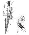
- FIG. 1 shows, as a reminder of the state of the technique, an articulated frame classic design.
- the "carrier” or “vehicle” part of the machine consists of a front frame 1 with two wheels 2, and a rear chassis 3 with two wheels 4.
- the front chassis 1 is connected to the rear frame 3 by an articulation intermediate 5, which defines an axis of articulation vertical 6.
- the front frame 1 carries one or two arms of drilling 7, each provided with a slide 8 along which is displaceable a drilling apparatus 9 of the kind hydraulic hammer drill.
- the front frame 1 door still the driving and working position 10 of the machine, surmounted by a protective roof 11.
- FIG. 2 to 4 show a form of realization of a drilling machine with articulated chassis according to the invention, using the same reference marks in FIG. 1, this machine being provided with two drill arms 7 which, for the sake of clarity, were not shown on the perspective view of the figure 2.
- the front chassis 1 to two wheels 2 carries the drill arms 7 and the post of pipe 10 surmounted by the protective roof.
- the front frame 1 is extended towards the rear, behind the hinge pin 6 with the chassis back 3, by a part 13 that supports some electrical and hydraulic equipment of the machine.
- the part 13, extending the front frame 1 to the rear extends above the front portion 14 of the frame rear 3, up to the top of the two wheels 4 of this chassis back 3.
- the equipment mounted in Part 13, extending the front frame 1 to the rear, can include the oil tank and engines such as the one visible in 15.
- the others usual equipment is still supported, in 12, by the rear frame 3.
- the position and mass of the part 13, extending the chassis before 1 towards the rear contribute to the lateral stability of the machine during the turn in particular in case of strong steering, corresponding to a large angle between the front frame 1 and rear frame 3.
Landscapes
- Engineering & Computer Science (AREA)
- Mining & Mineral Resources (AREA)
- Geology (AREA)
- Life Sciences & Earth Sciences (AREA)
- Geochemistry & Mineralogy (AREA)
- Structural Engineering (AREA)
- Environmental & Geological Engineering (AREA)
- General Life Sciences & Earth Sciences (AREA)
- Physics & Mathematics (AREA)
- Civil Engineering (AREA)
- General Engineering & Computer Science (AREA)
- Fluid Mechanics (AREA)
- Body Structure For Vehicles (AREA)
- Agricultural Machines (AREA)
- Earth Drilling (AREA)
- Operation Control Of Excavators (AREA)
- Arrangement Or Mounting Of Propulsion Units For Vehicles (AREA)
- Perforating, Stamping-Out Or Severing By Means Other Than Cutting (AREA)
- Forklifts And Lifting Vehicles (AREA)
Claims (4)
- Bohrgerät auf Rädern, deren Abschnitt "Träger" oder "Fahrzeug" ein vorderes Fahrgestell (1) mit zwei Rädern (2) und ein hinteres Fahrgestell (3) mit zwei Rädern (4) aufweist, wobei das vordere Fahrgestell (1) und das hintere Fahrgestell (3) miteinander über ein Zwischengelenk (5) um eine im Wesentlichen vertikale Achse (6) herum verbunden sind, wobei das eine der Fahrgestelle über einen Abschnitt des anderen Fahrgestells hinaus verlängert ist, und wobei das Gerät mindestens einen Bohrarm (7) und einen Fahr- und Arbeitsstand (10) aufweist, dadurch gekennzeichnet, dass das vordere Fahrgestell (1) zur Erhöhung der Seitenstabilität des Gerätes bei Schwenkung nach hinten (nach 13) hinter der Achse des Zwischengelenks (6) und über einem Abschnitt (14) des hinteren Fahrgestells (3) verlängert ausgebildet ist, wobei das vordere Fahrgestell (1) den Bohrarm oder die Bohrarme (7) und den Fahr- und Arbeitsstand (10) des Gerätes trägt.
- Bohrgerät nach Anspruch 1, dadurch gekennzeichnet, dass das zur Rückseite hin verlängerte vordere Fahrgestell (1) außer dem Bohrarm oder den Bohrarmen (7) und außer dem Fahr- und Arbeitsstands (10) des Gerätes einen Teil insbesondere der elektrischen und/oder hydraulischen Ausrüstung (15) des Gerätes trägt.
- Bohrgerät nach Anspruch 2, dadurch gekennzeichnet, dass das vordere Fahrgestell (1) zur Rückseite hin (nach 13) über einen Abschnitt (14) des hinteren Fahrgestells (3) bis über die Räder (4) des hinteren Fahrgestells (3) verlängert ausgebildet ist.
- Bohrgerät nach Anspruch 1 oder 2, dadurch gekennzeichnet, dass das zur Rückseite hin (nach 13) verlängerte vordere Fahrgestell (1) in der Eigenschaft als Ausrüstungen den Öltank und die Elektromotoren (15) des Gerätes trägt.
Applications Claiming Priority (2)
| Application Number | Priority Date | Filing Date | Title |
|---|---|---|---|
| FR9709112 | 1997-07-11 | ||
| FR9709112A FR2765912B1 (fr) | 1997-07-11 | 1997-07-11 | Engin de foration monte sur roues, a chassis articule |
Publications (2)
| Publication Number | Publication Date |
|---|---|
| EP0890704A1 EP0890704A1 (de) | 1999-01-13 |
| EP0890704B1 true EP0890704B1 (de) | 2005-02-02 |
Family
ID=9509341
Family Applications (1)
| Application Number | Title | Priority Date | Filing Date |
|---|---|---|---|
| EP98420118A Expired - Lifetime EP0890704B1 (de) | 1997-07-11 | 1998-07-09 | Bohrgerät auf Rädern mit einem schwenkbarem Rahmen |
Country Status (8)
| Country | Link |
|---|---|
| US (1) | US6152244A (de) |
| EP (1) | EP0890704B1 (de) |
| AT (1) | ATE288533T1 (de) |
| AU (1) | AU728789B2 (de) |
| CA (1) | CA2241799C (de) |
| DE (1) | DE69828846T2 (de) |
| ES (1) | ES2236881T3 (de) |
| FR (1) | FR2765912B1 (de) |
Families Citing this family (16)
| Publication number | Priority date | Publication date | Assignee | Title |
|---|---|---|---|---|
| EP1436483B1 (de) * | 2001-10-09 | 2006-01-04 | MacDonald, Claude | Mehrzweckbohrwagen |
| FR2856727B1 (fr) | 2003-06-26 | 2005-10-21 | Sandvik Tamrock Secoma Sas | Vehicule porteur pour machine de foration ou de boulonnage |
| US7387172B2 (en) * | 2005-06-10 | 2008-06-17 | Vandeligt Gerald J | Modular self-propelled drilling apparatus |
| ITPC20060022A1 (it) * | 2006-04-14 | 2007-10-15 | Egtechnology Srl | Macchina perforatrice migliorata |
| FI122591B (fi) * | 2010-05-25 | 2012-04-13 | Sandvik Mining & Constr Oy | Kallionporauslaite, menetelmä sen ajolaitteiston lämpötilan hallitsemiseksi sekä nestejäähdytysjärjestelmä |
| CN102352751B (zh) * | 2011-10-10 | 2014-12-31 | 攀钢集团工程技术有限公司 | 撬毛石机 |
| JP6153302B2 (ja) * | 2012-07-26 | 2017-06-28 | 古河ロックドリル株式会社 | 作業車両用作業床 |
| SE536713C2 (sv) * | 2012-10-30 | 2014-06-10 | Atlas Copco Rock Drills Ab | Borrigg jämte förfarande för manövrering av en borrigg |
| CN104196446A (zh) * | 2014-08-29 | 2014-12-10 | 廊坊景隆重工机械有限公司 | 一种配套连续采煤机使用的六臂全液压锚杆锚索钻车 |
| CN104265166A (zh) * | 2014-09-17 | 2015-01-07 | 北京景隆重工机械有限公司 | 一种配套连续采煤机使用的八臂全液压锚杆锚索钻车 |
| US20160138299A1 (en) * | 2014-10-20 | 2016-05-19 | John Powers, III | Multiple driver head post driving system |
| PL71195Y1 (pl) * | 2015-01-12 | 2020-01-31 | Mine Master Spolka Z Ograniczona Odpowiedzialnoscia | Samojezdny wóz wiercący do niskich wyrobisk |
| SE540556C2 (sv) * | 2015-07-03 | 2018-10-02 | Komatsu Forest Ab | System för stabilisering av fordon samt förfarande för stabilisering av fordon |
| WO2017007344A1 (es) * | 2015-07-09 | 2017-01-12 | Resemin S.A. | Vehiculo autopropulsado de perforacion de rocas para minería subterránea de dimensiones reducidas, montada sobre ruedas y con chasis articulado |
| CA2960613C (en) * | 2016-10-31 | 2019-02-26 | Yves Nelson | Gantry and quick connect mechanism for interchanging drilling and bolting assemblies and method of interchanging bolting assemblies |
| EP4095346B1 (de) * | 2021-05-27 | 2024-07-31 | Sandvik Mining and Construction Oy | Umsetzungssteuerung eines unterirdischen bohrgestells |
Family Cites Families (12)
| Publication number | Priority date | Publication date | Assignee | Title |
|---|---|---|---|---|
| US2827715A (en) * | 1955-09-23 | 1958-03-25 | Wagner Tractor Inc | Logging apparatus |
| US3157239A (en) * | 1961-09-07 | 1964-11-17 | Gen Motors Corp | Four wheel drive, two-engine, articulated frame tractor |
| US3237790A (en) * | 1963-06-14 | 1966-03-01 | Hough Co Frank | Articulated four-wheel drive earthworking vehicle |
| US3435908A (en) * | 1967-03-01 | 1969-04-01 | Caterpillar Tractor Co | Articulated crawler tractor construction |
| US3744574A (en) * | 1971-07-14 | 1973-07-10 | W Carley | Mobile rock drilling unit |
| US3823902A (en) * | 1972-07-12 | 1974-07-16 | H Bumueller | Articulated vehicle |
| US3811699A (en) * | 1972-08-21 | 1974-05-21 | Caterpillar Tractor Co | Axle trunnion support arrangement |
| PL74598B2 (de) * | 1972-11-04 | 1974-12-31 | Fabryka Maszyn Budowlanychpo | |
| US4072354A (en) * | 1976-05-06 | 1978-02-07 | William Machinery Limited | Breaker apparatus |
| US4363519A (en) * | 1980-10-14 | 1982-12-14 | Joy Manufacturing Company | Continuous mining machine |
| AT387262B (de) * | 1985-02-01 | 1988-12-27 | Ver Edelstahlwerke Ag | Vorrichtung zum bohren in gestein, erz od.dgl. |
| GB8909389D0 (en) * | 1989-04-25 | 1989-06-14 | Thomas Grenville J D | Mobile drilling rig |
-
1997
- 1997-07-11 FR FR9709112A patent/FR2765912B1/fr not_active Expired - Fee Related
-
1998
- 1998-07-08 US US09/111,854 patent/US6152244A/en not_active Expired - Lifetime
- 1998-07-09 EP EP98420118A patent/EP0890704B1/de not_active Expired - Lifetime
- 1998-07-09 DE DE69828846T patent/DE69828846T2/de not_active Expired - Fee Related
- 1998-07-09 ES ES98420118T patent/ES2236881T3/es not_active Expired - Lifetime
- 1998-07-09 AT AT98420118T patent/ATE288533T1/de not_active IP Right Cessation
- 1998-07-10 AU AU76103/98A patent/AU728789B2/en not_active Ceased
- 1998-07-10 CA CA002241799A patent/CA2241799C/fr not_active Expired - Fee Related
Also Published As
| Publication number | Publication date |
|---|---|
| DE69828846T2 (de) | 2006-05-04 |
| ES2236881T3 (es) | 2005-07-16 |
| EP0890704A1 (de) | 1999-01-13 |
| CA2241799C (fr) | 2003-01-14 |
| US6152244A (en) | 2000-11-28 |
| CA2241799A1 (fr) | 1999-01-11 |
| AU7610398A (en) | 1999-01-21 |
| DE69828846D1 (de) | 2005-03-10 |
| FR2765912A1 (fr) | 1999-01-15 |
| AU728789B2 (en) | 2001-01-18 |
| ATE288533T1 (de) | 2005-02-15 |
| FR2765912B1 (fr) | 1999-12-17 |
Similar Documents
| Publication | Publication Date | Title |
|---|---|---|
| CA2241799C (fr) | Engin de foration monte sur roues, a chassis articule | |
| EP0046234B1 (de) | Material- und Bodenbewegungsfahrzeug | |
| FR2595107A1 (fr) | Vehicule de type pelleteuse a pivotement complet a rayon reduit pour faciliter les operations dans un site resserre | |
| WO1987001085A1 (fr) | Vehicule, notamment motoneige | |
| FR2475516A1 (fr) | Pupitre de commande pour engins portant une nacelle pour un ouvrier au bout d'une fleche telescopique | |
| CA2174789A1 (fr) | Engin de travaux publics dont l'outil de travail est monte a l'extremite d'un bras articule | |
| FR2796910A1 (fr) | Chariot elevateur a fourche a faible hauteur de levage | |
| FR2717139A1 (fr) | Véhicule pour le transport de matériels de golf. | |
| EP0100926B1 (de) | Fahrzeug zur Handhabung von Materialien mit orientierbarem Ausleger und eingebautem Stabilisiergestell | |
| FR2646823A1 (fr) | Structure avant pour vehicule automobile et vehicule equipe de cette structure | |
| FR2577746A1 (fr) | Porte-outil avant pour tracteur agricole | |
| EP0579564A1 (de) | Mit einem Schlepper zu verbindender Mäher mit einer verbesserten Abstellvorrichtung | |
| FR2725191A1 (fr) | Vehicule de travaux comprenant un chassis monte sur roues et un bras telescopique | |
| CH350781A (fr) | Grue | |
| FR2471308A2 (fr) | Perfectionnements aux vehicules agricoles | |
| EP0750702B1 (de) | Baggerlader | |
| FR2507688A1 (fr) | Engin polyvalent de terrassement et de manutention | |
| WO2022106778A1 (fr) | Engin de manutention a bras telescopique | |
| FR2692317A3 (fr) | Machine opératrice automobile pour la mise en Óoeuvre de béton de remblai. | |
| FR2562923A1 (fr) | Chassis pour compacteur vibrant, permettant une meilleure visibilite de la cabine | |
| BE906105A (fr) | Perfectionnements du dispositif de levage des vehicules compacts de manutention. | |
| FR2723386A1 (fr) | Machine d'abattage, d'excavation, de creusement et de chargement de materiaux | |
| FR2629438A1 (fr) | Structure de liaison, a dispositifs elevateur et basculant, pour engins porte-outils | |
| FR2488195A2 (fr) | Dispositif de hissage et de transport de charges unitaires sur vehicule | |
| FR2501143A1 (fr) | Vehicule tout terrain |
Legal Events
| Date | Code | Title | Description |
|---|---|---|---|
| PUAI | Public reference made under article 153(3) epc to a published international application that has entered the european phase |
Free format text: ORIGINAL CODE: 0009012 |
|
| AK | Designated contracting states |
Kind code of ref document: A1 Designated state(s): AT CH DE ES FI FR GB GR IT LI SE |
|
| AX | Request for extension of the european patent |
Free format text: AL;LT;LV;MK;RO;SI |
|
| 17P | Request for examination filed |
Effective date: 19990705 |
|
| AKX | Designation fees paid |
Free format text: AT CH DE ES FI FR GB GR IT LI SE |
|
| RAP1 | Party data changed (applicant data changed or rights of an application transferred) |
Owner name: SANDVIK TAMROCK SECOMA S.A. |
|
| 17Q | First examination report despatched |
Effective date: 20040308 |
|
| GRAP | Despatch of communication of intention to grant a patent |
Free format text: ORIGINAL CODE: EPIDOSNIGR1 |
|
| GRAS | Grant fee paid |
Free format text: ORIGINAL CODE: EPIDOSNIGR3 |
|
| GRAA | (expected) grant |
Free format text: ORIGINAL CODE: 0009210 |
|
| AK | Designated contracting states |
Kind code of ref document: B1 Designated state(s): AT CH DE ES FI FR GB GR IT LI SE |
|
| PG25 | Lapsed in a contracting state [announced via postgrant information from national office to epo] |
Ref country code: GB Free format text: LAPSE BECAUSE OF FAILURE TO SUBMIT A TRANSLATION OF THE DESCRIPTION OR TO PAY THE FEE WITHIN THE PRESCRIBED TIME-LIMIT Effective date: 20050202 Ref country code: AT Free format text: LAPSE BECAUSE OF FAILURE TO SUBMIT A TRANSLATION OF THE DESCRIPTION OR TO PAY THE FEE WITHIN THE PRESCRIBED TIME-LIMIT Effective date: 20050202 |
|
| REG | Reference to a national code |
Ref country code: GB Ref legal event code: FG4D Free format text: NOT ENGLISH |
|
| REG | Reference to a national code |
Ref country code: CH Ref legal event code: EP |
|
| REF | Corresponds to: |
Ref document number: 69828846 Country of ref document: DE Date of ref document: 20050310 Kind code of ref document: P |
|
| PG25 | Lapsed in a contracting state [announced via postgrant information from national office to epo] |
Ref country code: GR Free format text: LAPSE BECAUSE OF FAILURE TO SUBMIT A TRANSLATION OF THE DESCRIPTION OR TO PAY THE FEE WITHIN THE PRESCRIBED TIME-LIMIT Effective date: 20050502 |
|
| REG | Reference to a national code |
Ref country code: SE Ref legal event code: TRGR |
|
| REG | Reference to a national code |
Ref country code: ES Ref legal event code: FG2A Ref document number: 2236881 Country of ref document: ES Kind code of ref document: T3 |
|
| PG25 | Lapsed in a contracting state [announced via postgrant information from national office to epo] |
Ref country code: LI Free format text: LAPSE BECAUSE OF NON-PAYMENT OF DUE FEES Effective date: 20050731 Ref country code: CH Free format text: LAPSE BECAUSE OF NON-PAYMENT OF DUE FEES Effective date: 20050731 |
|
| GBV | Gb: ep patent (uk) treated as always having been void in accordance with gb section 77(7)/1977 [no translation filed] |
Effective date: 20050202 |
|
| PLBE | No opposition filed within time limit |
Free format text: ORIGINAL CODE: 0009261 |
|
| STAA | Information on the status of an ep patent application or granted ep patent |
Free format text: STATUS: NO OPPOSITION FILED WITHIN TIME LIMIT |
|
| 26N | No opposition filed |
Effective date: 20051103 |
|
| REG | Reference to a national code |
Ref country code: CH Ref legal event code: PL |
|
| PGFP | Annual fee paid to national office [announced via postgrant information from national office to epo] |
Ref country code: ES Payment date: 20080718 Year of fee payment: 11 Ref country code: DE Payment date: 20080715 Year of fee payment: 11 |
|
| PGFP | Annual fee paid to national office [announced via postgrant information from national office to epo] |
Ref country code: FR Payment date: 20080425 Year of fee payment: 11 Ref country code: FI Payment date: 20080704 Year of fee payment: 11 Ref country code: IT Payment date: 20080726 Year of fee payment: 11 |
|
| REG | Reference to a national code |
Ref country code: FR Ref legal event code: ST Effective date: 20100331 |
|
| PG25 | Lapsed in a contracting state [announced via postgrant information from national office to epo] |
Ref country code: FR Free format text: LAPSE BECAUSE OF NON-PAYMENT OF DUE FEES Effective date: 20090731 Ref country code: FI Free format text: LAPSE BECAUSE OF NON-PAYMENT OF DUE FEES Effective date: 20090709 |
|
| PG25 | Lapsed in a contracting state [announced via postgrant information from national office to epo] |
Ref country code: DE Free format text: LAPSE BECAUSE OF NON-PAYMENT OF DUE FEES Effective date: 20100202 |
|
| REG | Reference to a national code |
Ref country code: ES Ref legal event code: FD2A Effective date: 20090710 |
|
| PG25 | Lapsed in a contracting state [announced via postgrant information from national office to epo] |
Ref country code: ES Free format text: LAPSE BECAUSE OF NON-PAYMENT OF DUE FEES Effective date: 20090710 |
|
| PG25 | Lapsed in a contracting state [announced via postgrant information from national office to epo] |
Ref country code: IT Free format text: LAPSE BECAUSE OF NON-PAYMENT OF DUE FEES Effective date: 20090709 |
|
| PGFP | Annual fee paid to national office [announced via postgrant information from national office to epo] |
Ref country code: SE Payment date: 20140711 Year of fee payment: 17 |
|
| REG | Reference to a national code |
Ref country code: SE Ref legal event code: EUG |
|
| PG25 | Lapsed in a contracting state [announced via postgrant information from national office to epo] |
Ref country code: SE Free format text: LAPSE BECAUSE OF NON-PAYMENT OF DUE FEES Effective date: 20150710 |