EP0890710A2 - Dampfkühlung für Turbinenschaufeln - Google Patents
Dampfkühlung für Turbinenschaufeln Download PDFInfo
- Publication number
- EP0890710A2 EP0890710A2 EP98112312A EP98112312A EP0890710A2 EP 0890710 A2 EP0890710 A2 EP 0890710A2 EP 98112312 A EP98112312 A EP 98112312A EP 98112312 A EP98112312 A EP 98112312A EP 0890710 A2 EP0890710 A2 EP 0890710A2
- Authority
- EP
- European Patent Office
- Prior art keywords
- steam
- passage
- blade
- moving blade
- gas turbine
- Prior art date
- Legal status (The legal status is an assumption and is not a legal conclusion. Google has not performed a legal analysis and makes no representation as to the accuracy of the status listed.)
- Granted
Links
- 238000001816 cooling Methods 0.000 title claims abstract description 62
- 238000011084 recovery Methods 0.000 claims abstract description 40
- 238000007789 sealing Methods 0.000 claims description 18
- 230000035882 stress Effects 0.000 abstract description 6
- 230000008646 thermal stress Effects 0.000 abstract description 4
- 230000002265 prevention Effects 0.000 abstract 1
- 239000007789 gas Substances 0.000 description 29
- 238000007689 inspection Methods 0.000 description 4
- 238000000034 method Methods 0.000 description 4
- 230000000694 effects Effects 0.000 description 3
- 230000006866 deterioration Effects 0.000 description 2
- 239000000567 combustion gas Substances 0.000 description 1
- 238000012423 maintenance Methods 0.000 description 1
- 238000012986 modification Methods 0.000 description 1
- 230000004048 modification Effects 0.000 description 1
Images



Classifications
-
- F—MECHANICAL ENGINEERING; LIGHTING; HEATING; WEAPONS; BLASTING
- F01—MACHINES OR ENGINES IN GENERAL; ENGINE PLANTS IN GENERAL; STEAM ENGINES
- F01D—NON-POSITIVE DISPLACEMENT MACHINES OR ENGINES, e.g. STEAM TURBINES
- F01D5/00—Blades; Blade-carrying members; Heating, heat-insulating, cooling or antivibration means on the blades or the members
- F01D5/12—Blades
- F01D5/14—Form or construction
- F01D5/18—Hollow blades, i.e. blades with cooling or heating channels or cavities; Heating, heat-insulating or cooling means on blades
-
- F—MECHANICAL ENGINEERING; LIGHTING; HEATING; WEAPONS; BLASTING
- F01—MACHINES OR ENGINES IN GENERAL; ENGINE PLANTS IN GENERAL; STEAM ENGINES
- F01D—NON-POSITIVE DISPLACEMENT MACHINES OR ENGINES, e.g. STEAM TURBINES
- F01D11/00—Preventing or minimising internal leakage of working-fluid, e.g. between stages
- F01D11/005—Sealing means between non relatively rotating elements
- F01D11/006—Sealing the gap between rotor blades or blades and rotor
-
- F—MECHANICAL ENGINEERING; LIGHTING; HEATING; WEAPONS; BLASTING
- F05—INDEXING SCHEMES RELATING TO ENGINES OR PUMPS IN VARIOUS SUBCLASSES OF CLASSES F01-F04
- F05D—INDEXING SCHEME FOR ASPECTS RELATING TO NON-POSITIVE-DISPLACEMENT MACHINES OR ENGINES, GAS-TURBINES OR JET-PROPULSION PLANTS
- F05D2260/00—Function
- F05D2260/20—Heat transfer, e.g. cooling
- F05D2260/232—Heat transfer, e.g. cooling characterized by the cooling medium
- F05D2260/2322—Heat transfer, e.g. cooling characterized by the cooling medium steam
Definitions
- the present invention relates to a gas turbine moving blade steam cooling system, and more specifically to a structure thereof which is able to prevent strength lowering of blade root portion and also to prevent steam leakage.
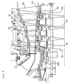
- Fig. 8 is a cross sectional view of a prior art gas turbine interior and shows flows of cooling air in a moving blade portion.
- numeral 50 designates a stationary blade
- numeral 51 designates an outer shroud
- numeral 52 designates an inner shroud
- Numeral 60 designates a moving blade, which is fixed to a blade root portion 62 of a turbine disc 61 and rotates between stationary blades 50.
- the moving blade 60 is cooled by air which is a part of rotor cooling air. That is, there is bored a radial hole 65 in the blade root portion 62 and the rotor cooling air 100 is introduced into each disc cavity 64 to be further introduced into a lower portion of a platform 63 via the radial hole 65 and then is supplied into the moving blade 60.
- Fig. 9 is a cross sectional view of a moving blade portion and a stationary blade portion of gas turbine of said structure.
- numeral 50 designates a stationary blade, which has an outer shroud 51 and an inner shroud 52 as well as an air pipe 53 extending in a blade height direction and passing through the blade interior.
- Seal air 110 is fed therethrough from the outer shroud 51 side into a cavity 54 so that pressure in the cavity 54 is made higher than that in a combustion gas passage and the seal air 110 further flows through a hole 57 and is partially discharged from a passage 56 so that a high temperature gas is prevented from coming therein.
- Numeral 55 designates a labyrinth seal, which is also for sealing the high temperature gas.
- the mentioned rotor cooling air 100 is introduced into the disc cavity 64 to be further introduced into a shank portion 66 of a lower portion of the platform 63 via a radial hole 65 which passes through interior of a rotor disc blade root portion 62 and then is supplied into a cooling air passage in the moving blade 60. Further, in place of using a portion of the rotor cooling air, it takes place also that air from a compressor is cooled by a cooler and is introduced into a disc cavity 64.
- the conventional art of cooling the gas turbine blades is an air cooling and, especially for the moving blades, a portion of the rotor cooling air is introduced to be used for cooling thereof.
- development is being done for employing a steam cooling method instead of using air, and in order to effect a steam cooling of the rotor system, it is imperative to employ such a structure that steam leakage is prevented enough and the blade root portion in which steam passages are provided may stand thermal stress enough.
- the present invention provides following means;
- cooling steam for the moving blade enters the steam passage from the steam supply passage on the disc side via the steam supply port to pass through the blade interior from the steam passage while cooling the blade and then returns to the steam recovery port of the steam passage to pass through the steam recovery passage on the disc side to be recovered.
- the steam while cooling the blade, receives heat without leakage of steam to be heated to a high temperature and is recovered to be used effectively.
- each said projection portion having no small corner portion, and the steam supply port and the steam recovery port of the steam passage are provided in each said projection portion, hence there is eliminated stress concentration due to heat at the blade root portion and the end portions thereof and strength lowering at these portions can be prevented.
- each said demountable joint pipe hence inspection, repair and replacement of the steam passages become facilitated and reliability of the steam cooling system of the moving blade is enhanced.
- each said seal plate for sealing each side face and therebetween of each said projection portion of mutually adjacent moving blades, hence leakage of steam can be prevented securely so that loss of steam is reduced and unfavorable influence given on the gas passages due to leakage of steam is reduced.
- Fig. 1 is a cross sectional view of a blade root portion which is applied to a gas turbine moving blade steam cooling system of a first embodiment according to the present invention
- Fig. 2 is a cross sectional view taken on line A-A of Fig. 1.
- numeral 1 designates a moving blade
- numeral 2 designates a platform
- numeral 3 designates a blade root portion and numeral 4a
- 4b designates a projection portion at each end along a turbine axial direction of the blade root portion 3 of mutually adjacent moving blades.
- Numeral 5 designates a steam passage, which extends between the projection portions 4a and 4b and communicates with a steam passage, not shown, leading to the blade interior from a lower portion of the moving blade 1.
- the steam passage 5 is provided at its end on a projection portion 4a side with a steam supply port 5a directed downwardly and at its end on a projection portion 4b side with a steam recovery port 5b directed downwardly.
- the steam supply port 5a and the steam recovery port 5b may be arranged reversely being replaced with each other.
- numerals 6, 7 and 8 designate seal plates for sealing each said blade root portion 3 and therebetween of mutually adjacent moving blades.
- unit 10 of the steam passage 5 is fitted between adjacent blade root portions 3 so as to come in close contact with curved surfaces of the blade root portions 3 and is provided within its interior with a hole 11 through which steam passes.
- the steam supply port 5a connects to a steam supply passage 20 provided in a disc portion and the steam recovery port 5b connects to a steam recovery passage 21 provided also in the disc portion.
- cooling steam is supplied from the steam supply passage 20 in the disc portion to flow through the steam supply port 5a and the steam passage 5 in the projection portion 4a and enters the lower portion of the moving blade 1 to pass through a steam passage in the blade, not shown, while cooling the blade and then returns to the steam passage 5 in the projection portion 4b to be recovered through the steam recovery port 5b and the steam recovery passage 21 in the disc portion.
- the steam passage 5 communicates respectively with the steam supply passage 20 and the steam recovery passage 21, both provided in the disc portion, and further the steam supply side and the steam recovery side between adjacent blade root portions are sealed by seal plates 8, 8, respectively, hence leakage of steam is prevented and loss of steam amount is reduced.
- each end portion along the turbine axial direction of the blade root portion 3 is projected, as compared with the prior art, so as to form the projection portion 4a, 4b in which corner portions are rounded and the steam supply port 5a and the steam recovery port 5b of the steam passage S are provided downwardly to the steam passage 5 in the projection portions 4a and 4b, respectively, hence unfavorable influence given by stress concentration due to heat at these portions can be mitigated.
- Fig. 3 is a cross sectional view of a blade root portion which is applied to a gas turbine moving blade steam cooling system of a second embodiment according to the present invention.
- numerals 1 to 6, 8, 20 and 21 designate respectively same parts as those of the first embodiment shown in Fig. 1 with description therefor being omitted and the second embodiment is featured in a pipe-like joint 30, which will be described below.
- each end portion along a turbine axial direction of a blade root portion 3 is projected, as compared with the prior art, so as to form a projection portion 4a, 4b and a steam passage 5 has its each end portion extending downwardly in the projection portions 4a and 4b, respectively.
- a steam passage 5 has its each end portion extending downwardly in the projection portions 4a and 4b, respectively.
- mounting portions 33, 34 in which the end portions of the steam passage 5 and the end portions of the steam supply passage 20 and the steam recovery passage 21 are worked so that said pipe-like joint 30 may be inserted thereinto.
- Fig. 4 is an enlarged detailed view of portion B of Fig. 3 showing state of mounting the pipe-like joint 30 and Figs. 5(a) to (d) show procedures of mounting.
- the mounting portion 33 on the blade side of the pipe-like joint 30 is made in a round shape for a good mountability and the mounting portion 34 on the disc side of same is made in a regular cylindrical shape for a good slidability.
- a flange-like projection portion 31 is formed on upper side of the pipe-like joint 30.
- Numeral 32 designates a fixing piece for fixing the pipe-like joint 30 finally.
- Fig. 6 is a cross sectional view showing another example of the pipe-like joint 30 of the second embodiment, which is basically same as that shown in Figs. 3 and 4 except that the pipe-like joint 30 of the present example has a flange-like projection portion 31 each on its upper portion and lower portion, said projection portion 31 being slidable in a blade side mounting portion 33 and in a disc side mounting portion 34, and the pipe-like joint 30 slides upwardly by action of centrifugal force so as to cause a blade side steam passage and a disc side steam passage to communicate with each other.
- the shape of the pipe-like joint is not limited to those shown in the figures but may naturally be used with modified forms as the case may be.
- cooling steam is supplied from the steam supply passage 20 to flow through the steam passage 5 in the projection portion 4a and, after cooling the blade interior, is recovered through the steam recovery passage 21 in the projection portion 4b.
- same effect as that of the first embodiment can be obtained.
- by use of the pipe-like joint 30 which is demountable inspection of the passages of the steam cooling system becomes facilitated.
- Fig. 7 is a cross sectional view of a main part of a blade root portion which is applied to a gas turbine moving blade steam cooling system of a third embodiment according to the present invention.
- same part as that shown in said embodiments is given same numeral and repeated description is omitted to the extent possible.
- a pipe-like joint 30 causes a steam passage 5 of a blade root portion 3 of turbine blade and a steam supply passage 20 of disc portion to communicate with each other and forms at its lower portion connecting to the disc portion a disc side seal point 43 of which central portion has a spherical surface of a small radius of curvature and abuts on the blade root portion, and there are provided an O-ring 40 on a turbine rotational center side of the disc side seal point 43 and an O-ring support bush 41 abutting on said O-ring on a further turbine rotational center side thereof.
- a blade side seal point 42 having a spherical surface of a large radius of curvature and abutting on the blade root portion 3.
- the blade side seal point 42 of the pipe-like joint 30 which has the spherical surface of large radius of curvature to abut on the blade root portion 3 so as to be able to maintain seal surface pressure due to centrifugal force and the disc side seal point 43 of the pipe-like joint 30 which cannot receive the seal surface pressure due to centrifugal force but can obtain a sealing ability by making a gap of fitting between itself and the disc portion minimum, hence sealing of the pipe-like joint 30 is attained well.
- the O-ring support bush 41 provided on the further turbine rotational center side of the O-ring 40 to abut on the O-ring 40 receives centrifugal force acting thereon so as to enhance seal surface pressure of the O-ring 40, thereby said sealing function can be maintained stably.
- the gas turbine moving blade steam cooling system said moving blade being fitted to a blade root portion via a platform, is characterized in comprising a projection portion projecting from each end along a turbine axial direction of an upper portion of said blade root portion which is under said platform and a steam passage, provided along the turbine axial direction between each said projection portion, communicating with a steam passage of said moving blade and having a steam supply port provided downwardly in one of each said projection portion and a steam recovery port provided downwardly in the other thereof so that said steam supply port and said steam recovery port are connected to a steam supply passage and a steam recovery passage, respectively, on a disc side.
- the cooling steam enters the steam passage from the steam supply passage to cool the blade interior and passes through the steam passage again and through the steam recovery port to be recovered into the steam recovery passage and leakage of steam can be prevented. Further, because the steam supply port and the steam recovery port are provided in the projection portions, stress concentration due to heat at the blade root end portions can be avoided owing to the shape of the projection portions and strength in the blade root portion can be enhanced.
- the gas turbine moving blade steam cooling system as set forth in the invention (1) above is characterized in that there is provided a demountable joint pipe to each of said steam supply port and said steam recovery port of the steam passage so that a lower portion of each said joint pipe is connected to said steam supply passage and said steam recovery passage, respectively.
- the gas turbine moving blade steam cooling system as set forth in the invention (1) or (2) above is characterized in that there is provided a seal plate for sealing each side surface and therebetween along a turbine rotational direction of each said projection portion of mutually adjacent moving blades.
- the gas turbine moving blade steam cooling system is characterized in comprising a pipe-like joint which causes a steam supply passage or a steam recovery passage provided in a disc portion to communicate with a steam passage provided in a blade root portion, an O-ring provided on a turbine rotational center side of a seal point of said pipe-like joint and a bush provided on the turbine rotational center side of said O-ring so as to abut on said O-ring.
Landscapes
- Engineering & Computer Science (AREA)
- Mechanical Engineering (AREA)
- General Engineering & Computer Science (AREA)
- Turbine Rotor Nozzle Sealing (AREA)
Applications Claiming Priority (6)
| Application Number | Priority Date | Filing Date | Title |
|---|---|---|---|
| JP18120597A JP3500045B2 (ja) | 1997-07-07 | 1997-07-07 | ガスタービン動翼の蒸気冷却システム |
| JP18120597 | 1997-07-07 | ||
| JP181205/97 | 1997-07-07 | ||
| JP18653997 | 1997-07-11 | ||
| JP18653997A JP3722956B2 (ja) | 1997-07-11 | 1997-07-11 | ガスタービン冷却通路継ぎ手部のシール構造 |
| JP186539/97 | 1997-07-11 |
Publications (3)
| Publication Number | Publication Date |
|---|---|
| EP0890710A2 true EP0890710A2 (de) | 1999-01-13 |
| EP0890710A3 EP0890710A3 (de) | 2000-03-22 |
| EP0890710B1 EP0890710B1 (de) | 2004-05-12 |
Family
ID=26500473
Family Applications (1)
| Application Number | Title | Priority Date | Filing Date |
|---|---|---|---|
| EP98112312A Expired - Lifetime EP0890710B1 (de) | 1997-07-07 | 1998-07-02 | Anordnung von Gasturbinenlaufschaufeln mit einem Dampfkühlungssystem |
Country Status (4)
| Country | Link |
|---|---|
| US (1) | US5971707A (de) |
| EP (1) | EP0890710B1 (de) |
| CA (1) | CA2242650C (de) |
| DE (1) | DE69823744T2 (de) |
Cited By (5)
| Publication number | Priority date | Publication date | Assignee | Title |
|---|---|---|---|---|
| EP1283328A1 (de) * | 2001-08-09 | 2003-02-12 | Siemens Aktiengesellschaft | Dichtungsbuchse für gekühlte Gasturbinenschaufeln |
| EP1291491A2 (de) | 2001-09-10 | 2003-03-12 | Mitsubishi Heavy Industries, Ltd. | Verbindungsmuffe für Kühlkanäle in Gasturbinen |
| EP1207324A3 (de) * | 2000-11-18 | 2003-12-10 | ALSTOM (Switzerland) Ltd | Dichtungsanordnung zwischen Bauteilen einer rotierenden Baugruppe sowie Verfahren zur Herstellung einer Dichtverbindung |
| FR2862338A1 (fr) * | 2003-11-17 | 2005-05-20 | Snecma Moteurs | Dispositif de liaison entre un distributeur et une enceinte d'alimentation pour injecteurs de fluide de refroidissement dans une turbomachine |
| EP3115552A3 (de) * | 2015-07-06 | 2017-03-29 | Siemens Aktiengesellschaft | Öffnungselement für turbinenstator und/oder rotorschaufeln |
Families Citing this family (6)
| Publication number | Priority date | Publication date | Assignee | Title |
|---|---|---|---|---|
| US7024763B2 (en) * | 2003-11-26 | 2006-04-11 | Formfactor, Inc. | Methods for making plated through holes usable as interconnection wire or probe attachments |
| DE102005037510A1 (de) * | 2005-08-10 | 2007-02-15 | Zf Friedrichshafen Ag | Rohrverbindung |
| US8353668B2 (en) * | 2009-02-18 | 2013-01-15 | United Technologies Corporation | Airfoil insert having a tab extending away from the body defining a portion of outlet periphery |
| US9797259B2 (en) * | 2014-03-07 | 2017-10-24 | Siemens Energy, Inc. | Turbine airfoil cooling system with cooling systems using high and low pressure cooling fluids |
| EP2949872A1 (de) * | 2014-05-27 | 2015-12-02 | Siemens Aktiengesellschaft | Turbomaschine mit einer Dichtung zur Trennung von Arbeitsflüssigkeit und Kühlflüssigkeit der Turbomaschine und Verwendung der Turbomaschine |
| US11066936B1 (en) * | 2020-05-07 | 2021-07-20 | Rolls-Royce Corporation | Turbine bladed disc brazed sealing plate with flow metering and axial retention features |
Family Cites Families (14)
| Publication number | Priority date | Publication date | Assignee | Title |
|---|---|---|---|---|
| US2974925A (en) * | 1957-02-11 | 1961-03-14 | John C Freche | External liquid-spray cooling of turbine blades |
| US2931623A (en) * | 1957-05-02 | 1960-04-05 | Orenda Engines Ltd | Gas turbine rotor assembly |
| US3370830A (en) * | 1966-12-12 | 1968-02-27 | Gen Motors Corp | Turbine cooling |
| US3715170A (en) * | 1970-12-11 | 1973-02-06 | Gen Electric | Cooled turbine blade |
| US3804551A (en) * | 1972-09-01 | 1974-04-16 | Gen Electric | System for the introduction of coolant into open-circuit cooled turbine buckets |
| CH582305A5 (de) * | 1974-09-05 | 1976-11-30 | Bbc Sulzer Turbomaschinen | |
| US4136516A (en) * | 1977-06-03 | 1979-01-30 | General Electric Company | Gas turbine with secondary cooling means |
| US4118136A (en) * | 1977-06-03 | 1978-10-03 | General Electric Company | Apparatus for attaching tubing to a rotating disk |
| US4648799A (en) * | 1981-09-22 | 1987-03-10 | Westinghouse Electric Corp. | Cooled combustion turbine blade with retrofit blade seal |
| GB2224082A (en) * | 1988-10-19 | 1990-04-25 | Rolls Royce Plc | Turbine disc having cooling and sealing arrangements |
| US5224818A (en) * | 1991-11-01 | 1993-07-06 | General Electric Company | Air transfer bushing |
| US5318404A (en) * | 1992-12-30 | 1994-06-07 | General Electric Company | Steam transfer arrangement for turbine bucket cooling |
| US5536143A (en) * | 1995-03-31 | 1996-07-16 | General Electric Co. | Closed circuit steam cooled bucket |
| DE19644543A1 (de) * | 1996-10-26 | 1998-04-30 | Asea Brown Boveri | Vorrichtung zur Dichtung des Strömungsüberganges eines Kühlmediums zwischen Rotor und Laufschaufel |
-
1998
- 1998-07-02 DE DE69823744T patent/DE69823744T2/de not_active Expired - Fee Related
- 1998-07-02 CA CA002242650A patent/CA2242650C/en not_active Expired - Fee Related
- 1998-07-02 US US09/109,379 patent/US5971707A/en not_active Expired - Lifetime
- 1998-07-02 EP EP98112312A patent/EP0890710B1/de not_active Expired - Lifetime
Cited By (10)
| Publication number | Priority date | Publication date | Assignee | Title |
|---|---|---|---|---|
| EP1207324A3 (de) * | 2000-11-18 | 2003-12-10 | ALSTOM (Switzerland) Ltd | Dichtungsanordnung zwischen Bauteilen einer rotierenden Baugruppe sowie Verfahren zur Herstellung einer Dichtverbindung |
| US6739594B2 (en) | 2000-11-18 | 2004-05-25 | Alstom Technology Ltd | Sealing arrangement between components of a rotating assembly as well as a method for producing a sealing joint |
| EP1283328A1 (de) * | 2001-08-09 | 2003-02-12 | Siemens Aktiengesellschaft | Dichtungsbuchse für gekühlte Gasturbinenschaufeln |
| EP1291491A2 (de) | 2001-09-10 | 2003-03-12 | Mitsubishi Heavy Industries, Ltd. | Verbindungsmuffe für Kühlkanäle in Gasturbinen |
| EP1291491A3 (de) * | 2001-09-10 | 2006-09-27 | Mitsubishi Heavy Industries, Ltd. | Verbindungsmuffe für Kühlkanäle in Gasturbinen |
| FR2862338A1 (fr) * | 2003-11-17 | 2005-05-20 | Snecma Moteurs | Dispositif de liaison entre un distributeur et une enceinte d'alimentation pour injecteurs de fluide de refroidissement dans une turbomachine |
| EP1538306A1 (de) | 2003-11-17 | 2005-06-08 | Snecma Moteurs | Bindungsvorrichtung zwischen einer Leitschaufel und ihrer Kühlmittelkammer in einer Turbomaschine |
| US7351030B2 (en) | 2003-11-17 | 2008-04-01 | Snecma Moteurs | Connection device for making a connection between a turbomachine nozzle and a feed enclosure for feeding cooling fluid to injectors |
| RU2361091C2 (ru) * | 2003-11-17 | 2009-07-10 | Снекма | Соединительное устройство для установки соединения между соплом турбомашины и камерой подачи для подведения охлаждающей текучей среды к инжекторам |
| EP3115552A3 (de) * | 2015-07-06 | 2017-03-29 | Siemens Aktiengesellschaft | Öffnungselement für turbinenstator und/oder rotorschaufeln |
Also Published As
| Publication number | Publication date |
|---|---|
| EP0890710B1 (de) | 2004-05-12 |
| DE69823744T2 (de) | 2005-04-28 |
| CA2242650C (en) | 2001-10-16 |
| DE69823744D1 (de) | 2004-06-17 |
| CA2242650A1 (en) | 1999-01-07 |
| EP0890710A3 (de) | 2000-03-22 |
| US5971707A (en) | 1999-10-26 |
Similar Documents
| Publication | Publication Date | Title |
|---|---|---|
| KR100379728B1 (ko) | 로터조립체용시라우드및로터조립체시라우드용블레이드외부공기시일 | |
| US6293089B1 (en) | Gas turbine | |
| US5358379A (en) | Gas turbine vane | |
| EP0864728B1 (de) | Kühlluftzufuhrsystem für die Schaufeln einer Gasturbine | |
| US4893987A (en) | Diffusion-cooled blade tip cap | |
| CA2368555C (en) | Gas turbine split ring | |
| US6139263A (en) | Flow machine with rotor and stator | |
| CA2242650C (en) | Gas turbine moving blade steam cooling system | |
| US6565322B1 (en) | Turbo-machine comprising a sealing system for a rotor | |
| US6682307B1 (en) | Sealing system for a rotor of a turbo engine | |
| CA2103428A1 (en) | Steam transfer arrangement for turbine bucket cooling | |
| JPH10246103A (ja) | ガスタービン翼 | |
| EP0860586B1 (de) | Verbindungsstück zur Zufuhr von Kühlfluid von einer Rotorscheibe zu einer Turbomaschinenschaufel | |
| EP0728258B1 (de) | Deckbandsegment einer turbine | |
| US7874791B2 (en) | Turbomachine | |
| JP2007518917A (ja) | タービン翼およびそのタービン翼を備えたガスタービン | |
| JP2006125402A (ja) | ガスタービンロータブレード | |
| JPH1122413A (ja) | ガスタービン静翼のシール装置 | |
| EP1790824B1 (de) | Kühlanordnung | |
| EP1061235B1 (de) | Axialdichtungssystem für einen dampfgekühlten Gasturbinenrotor | |
| JP3500045B2 (ja) | ガスタービン動翼の蒸気冷却システム | |
| JP2000186502A (ja) | ガスタービン | |
| KR101259205B1 (ko) | 열축적 세그먼트 | |
| US6189892B1 (en) | High differential pressure type end rotor seal | |
| EP0420243A1 (de) | Keramische Statorschaufel |
Legal Events
| Date | Code | Title | Description |
|---|---|---|---|
| PUAI | Public reference made under article 153(3) epc to a published international application that has entered the european phase |
Free format text: ORIGINAL CODE: 0009012 |
|
| 17P | Request for examination filed |
Effective date: 19980730 |
|
| AK | Designated contracting states |
Kind code of ref document: A2 Designated state(s): CH DE FR GB IT LI |
|
| AX | Request for extension of the european patent |
Free format text: AL;LT;LV;MK;RO;SI |
|
| PUAL | Search report despatched |
Free format text: ORIGINAL CODE: 0009013 |
|
| AK | Designated contracting states |
Kind code of ref document: A3 Designated state(s): AT BE CH CY DE DK ES FI FR GB GR IE IT LI LU MC NL PT SE |
|
| AX | Request for extension of the european patent |
Free format text: AL;LT;LV;MK;RO;SI |
|
| RIC1 | Information provided on ipc code assigned before grant |
Free format text: 7F 01D 5/08 A, 7F 02C 7/16 B, 7F 01D 5/18 B, 7F 01D 11/00 B |
|
| AKX | Designation fees paid |
Free format text: CH DE FR GB IT LI |
|
| 17Q | First examination report despatched |
Effective date: 20030327 |
|
| GRAP | Despatch of communication of intention to grant a patent |
Free format text: ORIGINAL CODE: EPIDOSNIGR1 |
|
| RTI1 | Title (correction) |
Free format text: GAS TURBINE MOVING BLADE ARRANGEMENT COMPRISING A STEAM COOLING SYSTEM |
|
| RTI1 | Title (correction) |
Free format text: GAS TURBINE MOVING BLADE ARRANGEMENT COMPRISING A STEAM COOLING SYSTEM |
|
| GRAS | Grant fee paid |
Free format text: ORIGINAL CODE: EPIDOSNIGR3 |
|
| GRAA | (expected) grant |
Free format text: ORIGINAL CODE: 0009210 |
|
| AK | Designated contracting states |
Kind code of ref document: B1 Designated state(s): CH DE FR GB IT LI |
|
| PG25 | Lapsed in a contracting state [announced via postgrant information from national office to epo] |
Ref country code: LI Free format text: LAPSE BECAUSE OF FAILURE TO SUBMIT A TRANSLATION OF THE DESCRIPTION OR TO PAY THE FEE WITHIN THE PRESCRIBED TIME-LIMIT Effective date: 20040512 Ref country code: IT Free format text: LAPSE BECAUSE OF FAILURE TO SUBMIT A TRANSLATION OF THE DESCRIPTION OR TO PAY THE FEE WITHIN THE PRESCRIBED TIME-LIMIT;WARNING: LAPSES OF ITALIAN PATENTS WITH EFFECTIVE DATE BEFORE 2007 MAY HAVE OCCURRED AT ANY TIME BEFORE 2007. THE CORRECT EFFECTIVE DATE MAY BE DIFFERENT FROM THE ONE RECORDED. Effective date: 20040512 Ref country code: FR Free format text: LAPSE BECAUSE OF FAILURE TO SUBMIT A TRANSLATION OF THE DESCRIPTION OR TO PAY THE FEE WITHIN THE PRESCRIBED TIME-LIMIT Effective date: 20040512 Ref country code: CH Free format text: LAPSE BECAUSE OF FAILURE TO SUBMIT A TRANSLATION OF THE DESCRIPTION OR TO PAY THE FEE WITHIN THE PRESCRIBED TIME-LIMIT Effective date: 20040512 |
|
| REG | Reference to a national code |
Ref country code: GB Ref legal event code: FG4D |
|
| REG | Reference to a national code |
Ref country code: CH Ref legal event code: EP |
|
| REF | Corresponds to: |
Ref document number: 69823744 Country of ref document: DE Date of ref document: 20040617 Kind code of ref document: P |
|
| PG25 | Lapsed in a contracting state [announced via postgrant information from national office to epo] |
Ref country code: GB Free format text: LAPSE BECAUSE OF NON-PAYMENT OF DUE FEES Effective date: 20040812 |
|
| REG | Reference to a national code |
Ref country code: CH Ref legal event code: PL |
|
| PLBE | No opposition filed within time limit |
Free format text: ORIGINAL CODE: 0009261 |
|
| STAA | Information on the status of an ep patent application or granted ep patent |
Free format text: STATUS: NO OPPOSITION FILED WITHIN TIME LIMIT |
|
| GBPC | Gb: european patent ceased through non-payment of renewal fee |
Effective date: 20040812 |
|
| 26N | No opposition filed |
Effective date: 20050215 |
|
| EN | Fr: translation not filed | ||
| PGFP | Annual fee paid to national office [announced via postgrant information from national office to epo] |
Ref country code: DE Payment date: 20080711 Year of fee payment: 11 |
|
| PG25 | Lapsed in a contracting state [announced via postgrant information from national office to epo] |
Ref country code: DE Free format text: LAPSE BECAUSE OF NON-PAYMENT OF DUE FEES Effective date: 20100202 |