EP0890748A1 - Steuereinrichtung für einen Pflug - Google Patents
Steuereinrichtung für einen Pflug Download PDFInfo
- Publication number
- EP0890748A1 EP0890748A1 EP98440148A EP98440148A EP0890748A1 EP 0890748 A1 EP0890748 A1 EP 0890748A1 EP 98440148 A EP98440148 A EP 98440148A EP 98440148 A EP98440148 A EP 98440148A EP 0890748 A1 EP0890748 A1 EP 0890748A1
- Authority
- EP
- European Patent Office
- Prior art keywords
- distributor
- cylinder
- chamber
- return
- pressure
- Prior art date
- Legal status (The legal status is an assumption and is not a legal conclusion. Google has not performed a legal analysis and makes no representation as to the accuracy of the status listed.)
- Granted
Links
- 239000012530 fluid Substances 0.000 claims description 110
- 230000008878 coupling Effects 0.000 claims description 22
- 238000010168 coupling process Methods 0.000 claims description 22
- 238000005859 coupling reaction Methods 0.000 claims description 22
- 238000004891 communication Methods 0.000 claims description 20
- 230000000670 limiting effect Effects 0.000 claims description 8
- 230000000694 effects Effects 0.000 description 10
- 230000002441 reversible effect Effects 0.000 description 9
- 238000010586 diagram Methods 0.000 description 8
- 238000011144 upstream manufacturing Methods 0.000 description 4
- 238000006073 displacement reaction Methods 0.000 description 3
- 230000007257 malfunction Effects 0.000 description 3
- 238000004904 shortening Methods 0.000 description 3
- 230000003068 static effect Effects 0.000 description 3
- 208000031968 Cadaver Diseases 0.000 description 2
- 238000002955 isolation Methods 0.000 description 1
- 238000012986 modification Methods 0.000 description 1
- 230000004048 modification Effects 0.000 description 1
- 230000036961 partial effect Effects 0.000 description 1
- 230000000717 retained effect Effects 0.000 description 1
- 239000002689 soil Substances 0.000 description 1
- 238000006467 substitution reaction Methods 0.000 description 1
Images


Classifications
-
- F—MECHANICAL ENGINEERING; LIGHTING; HEATING; WEAPONS; BLASTING
- F15—FLUID-PRESSURE ACTUATORS; HYDRAULICS OR PNEUMATICS IN GENERAL
- F15B—SYSTEMS ACTING BY MEANS OF FLUIDS IN GENERAL; FLUID-PRESSURE ACTUATORS, e.g. SERVOMOTORS; DETAILS OF FLUID-PRESSURE SYSTEMS, NOT OTHERWISE PROVIDED FOR
- F15B11/00—Servomotor systems without provision for follow-up action; Circuits therefor
- F15B11/16—Servomotor systems without provision for follow-up action; Circuits therefor with two or more servomotors
- F15B11/20—Servomotor systems without provision for follow-up action; Circuits therefor with two or more servomotors controlling several interacting or sequentially-operating members
-
- A—HUMAN NECESSITIES
- A01—AGRICULTURE; FORESTRY; ANIMAL HUSBANDRY; HUNTING; TRAPPING; FISHING
- A01B—SOIL WORKING IN AGRICULTURE OR FORESTRY; PARTS, DETAILS, OR ACCESSORIES OF AGRICULTURAL MACHINES OR IMPLEMENTS, IN GENERAL
- A01B3/00—Ploughs with fixed plough-shares
- A01B3/36—Ploughs mounted on tractors
- A01B3/40—Alternating ploughs
- A01B3/42—Turn-wrest ploughs
- A01B3/421—Turn-wrest ploughs with a headstock frame made in one piece
- A01B3/4215—Turn-wrest ploughs with a headstock frame made in one piece the headstock being provided with two or more hydraulic cylinders
Definitions
- This known device is intended to bring the plow from a working position in another working position.
- it has three distributors who are especially intended to control the first and second cylinders so as a first step, the supporting structure is moved laterally by so as to be brought closer to the longitudinal axis of the cylindrical joint and that the supporting structure is then rotated by 180 ° and that finally said supporting structure is again distant from said longitudinal axis.
- this known device also manages the return of different chambers of the cylinders so as to authorize or prohibit the return of fluid of said chambers so as to respect the operating order of the plow as previously described.
- One of the distributors is controlled on both sides by a respective command and by a reminder element.
- This distributor can occupy two positions: an initial position and another position, said return element being intended to maintain or recall said dispenser in its initial position.
- This distributor also has a throttle which is active when said distributor occupies its other position. This constriction is intended to create a pressure difference between the two control lines when crossed by a certain flow of fluid so as to cause said distributor to evolve from its initial position in its other position and to maintain it in this other position. When there is no longer a flow of fluid passing through the throttle, the distributor returns to its initial position under the effect of its return element.
- This known device arranged with a reversible plow, comprises a certain number of drawbacks.
- said distributors authorize on the one hand the supply of the second chamber of the first cylinder and at the same time the supply of the first chamber of the second cylinder and secondly the return of the fluid from the first chamber of the first cylinder and the return of the fluid from the second chamber of the second cylinder.
- Such control of the cylinders has a major drawback. Indeed, in this case, the first cylinder is shortened before the second cylinder did not lie down or substantially at the same time, which means that the supporting structure is moved laterally with respect to the coupling structure of away from the longitudinal axis of the front cylindrical joint or substantially at the same time as said supporting structure is pivoted around said cylindrical joint to effect the remaining 90 °.
- This known device arranged with a reversible plow also comprises a another drawback.
- the operator is sometimes called upon to intervene on the adjustment of plumb with the plow, which consists in defining the angular position of the structure load bearing with respect to the coupling structure in the two working positions of said plow.
- the operator normally controls the device as described previously until the supporting structure has released the stopper then the operator proceeds to the adjustment of said stop and finally he controls said device in reverse by means of a hydraulic power station which supplies in fluid said device, which allows to bring said supporting structure in its initial working position.
- a hydraulic power station which supplies in fluid said device, which allows to bring said supporting structure in its initial working position.
- distributors allow in particular the supply of the first and second second cylinder chambers.
- the difference in section between the first chamber and the second chamber of the second cylinder is intended to allow said second cylinder to extend to return the supporting structure to its position initial work. Often this difference in section is not sufficient to provide sufficient pressure to bring the supporting structure back into the its initial position, especially when there is a certain mass of soil that remains glued to the plowing bodies.
- the object of the present invention is to remedy the drawbacks of this known device and make its operation more reliable.
- the device according to the present invention allows reliably control one cylinder after another and avoid malfunctions.
- the invention also relates to an agricultural machine comprising two cylinders and a device for controlling said cylinders and having one or more many of the above features.
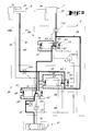
- the reversible plow (1) shown in Figure 1 is a plow with widths multiple which generally includes a coupling structure (2) linked to a coupling device (3) of a motor vehicle (4), a carrying structure (5), a first and second cylinders (6, 7) for moving said structure carrier (5) relative to said coupling structure (2) and a device (9) for controlling said first and said second cylinders (6, 7).
- a coupling structure (2) linked to a coupling device (3) of a motor vehicle (4), a carrying structure (5), a first and second cylinders (6, 7) for moving said structure carrier (5) relative to said coupling structure (2) and a device (9) for controlling said first and said second cylinders (6, 7).
- To the supporting structure (5) are linked to plowing bodies (10) by means of a articulation (11) of longitudinal axis (11a) substantially vertical around which can pivot the corresponding plow body (10) so as to be able to work a strip of land of different width.
- the supporting structure (5) can on the one hand be pivoted by 180 ° around an axis longitudinal (12a) substantially horizontal and directed in the direction of advance (13) and on the other hand be moved laterally relative to said structure coupling (2).
- the supporting structure (5) comprises a first part (15) linked to the coupling structure (2) by means of a cylindrical articulation (12) longitudinal axis (12a) described above and a second part (16) supporting the plow bodies (10).
- This second part (16) is, according to the example of embodiment shown, linked to the first part (15) by means of a device for link (17) comprising a main connecting rod (18) and two auxiliary connecting rods (19, 20), each connecting rod being linked to said first part (15) and to said second part (16) by means of an articulation (21, 22, 23, 24, 25, 26) respective to an axis longitudinal (21a, 22a, 23a, 24a, 25a, 26a) substantially vertical.
- a device for link (17) comprising a main connecting rod (18) and two auxiliary connecting rods (19, 20)
- each connecting rod being linked to said first part (15) and to said second part (16) by means of an articulation (21, 22, 23, 24, 25, 26) respective to an axis longitudinal (21a, 22a, 23a, 24a, 25a, 26a) substantially vertical.
- one of the connecting rods auxiliary (19) is composed of the first cylinder (6) allowing to move laterally the second part (16) of the supporting structure (5) relative to the first part (15) and the coupling structure (2) in a manner known by one skilled in the art.
- the first cylinder (6) lengthens, the second part (16) moves laterally as described above and at the same time rotates around a virtual point so as to approach the longitudinal axis (12a) of the cylindrical joint (12) and extend substantially in the extension of the coupling structure (2) according to a top view.
- the second part (16) moves away from the longitudinal axis (12a) so as to extend beyond the structure coupling (2).
- Such a design allows in particular to work a strip of more or less wide ground according to the position of the second part (16) of the supporting structure (5).
- the second cylinder (7) is linked on the one hand to the coupling structure (2) by means of a joint (28) located above the cylindrical joint (12) and with a longitudinal axis (28a) substantially parallel to the longitudinal axis (12a) of said cylindrical joint (12) and on the other hand to the first part (15) of the supporting structure (5) by means of a joint (not shown).
- This second cylinder (7) allows the carrier structure (5) to be pivoted 180 °, ie a half-turn. More precisely, when the second cylinder (7) shortens, the supporting structure (5) pivots around the longitudinal axis (12a) by 90 °, that is, a quarter turn, and then, said second cylinder (7) is extended to rotate said structure carrier (5) of additional 90 °.
- the folding / unfolding cylinder (6) and the turning cylinder (7) are double-acting cylinders each comprising first and second chambers (31, 32; 33, 34).
- first chamber (31) of the folding / unfolding cylinder (6) is more larger than the corresponding second chamber (32) and the first chamber (33) of the turning cylinder (7) is larger than the second chamber (34) corresponding.
- Such a circuit design (39) makes it possible in particular to respect the order actuator control (6, 7) as described above to ensure the turning the plow (1).
- each distributor (41, 42, 43) is, according to the schematic embodiment shown, a distributor (41, 42, 43) with drawers which can occupy two distinct positions, an initial position (55, 56, 57) and another position (58, 59, 60).
- each distributor (41, 42, 43) also has a return element (61, 62, 63) controlling the distributor (41, 42, 43) corresponding.
- each return element (61, 62, 63) is intended to maintain or to recall the corresponding distributor (41, 42, 43) to its initial position (55, 56, 57).
- each distributor (41, 42, 43) is controlled by three control lines (45, 46, 47, 48, 49, 50, 51, 52, 53).
- Each first control line (45, 48, 51) communicates with a small area control (65, 66, 67) intended to act on the distributor (41, 42, 43) corresponding in the opposite direction to its return element (61, 62, 63) of so as to bring said distributor (41, 42, 43) into its other position (58, 59, 60).
- Each second control line (46, 49, 52) communicates with a large control surface (68, 69, 70) intended to act on the distributor (41, 42, 43) corresponding in the opposite direction to its return element (61, 62, 63) of so as to bring said distributor (41, 42, 43) into its other position (58, 59, 60).
- each third control line (47, 50, 53) communicates with a large control surface (71, 72, 73) intended to act on the distributor (41, 42, 43) corresponding in the same direction as its return element (61, 62, 63) so as to maintain or recall said distributor (41, 42, 43) corresponding in its initial position (55, 56, 57).
- a low pressure in the third line of control (47, 50, 53) is more than enough to bring back or maintain the distributor (41, 42, 43) in its initial position even if the pressure of the first control line (45, 48, 51) is at the maximum (within the limits operating the device (9) and / or the hydraulic unit (37)).
- each distributor (41, 42, 43) has a means allowing the different steering surfaces (65, 66, 67, 68, 69, 70, 71, 72, 73) of the same distributor (41, 42, 43) between them so as to automatically return said distributor (41, 42, 43) to its initial position (55, 56, 57) when the device (9) is at rest.
- each drawer of a dispenser (41, 42, 43) can be provided with a calibrated hole extending longitudinally through said drawer so as to make communicate the different steering surfaces (65, 66, 67, 68, 69, 70, 71, 72, 73) corresponding to each other.
- each calibrated hole is represented by two throttles (41.1, 41.2, 42.1, 42.2, 43.1, 43.2), allowing the passage of the fluid to very low flow of the control surfaces (65, 66, 67, 68, 69, 70), located on one side of a distributor (41, 42, 43) to the corresponding control surface (71, 72, 73) located on the other side of said distributor (41, 42, 43) corresponding.
- This passage from fluid at very low flow rate has meaning only in static.
- first and the third distributors (41, 43) each have six holes while the second distributor (42) has seven ports, each port receiving a pipe.
- a first non-return valve (109) located on the fifth pipe (80) between the second chamber (32) of the folding / unfolding cylinder (6) and the ninth point of connection (96).
- This first non-return valve (109) can be controlled by the pressure in the fourth line (79) by means of a pressure line additional control (110) connected to said fourth line (79) at by means of a seventeenth connection point (111).
- This first non-return valve (109) is intended to authorize, when not ordered, only the passage of the fluid from the ninth connection point (96) to the second bedroom (32). When said first non-return valve (109) is controlled, it allows the passage of the fluid in both directions.
- This second non-return valve (112) located on the tenth line (92) between the first chamber (33) of the turning cylinder (7) and the twelfth connection point (102).
- This second non-return valve (112) can be controlled by the pressure prevailing in the sixteenth pipe (103) at means of another additional control line (113) connected to said sixteenth line (103) by means of an eighteenth connection point (114).
- This second non-return valve (112) is intended to authorize, when it is not controlled, only the passage of the fluid coming from the twelfth point of connection (102) to the first chamber (33). When said second valve non-return (112) is controlled, it allows the passage of the fluid in both directions.
- a third non-return valve (116) is also provided. located on a seventeenth pipe (117) connecting the first and the second lines (75, 76). To this end, the seventeenth pipe (117) is connected to the first pipe (75) by means of a nineteenth connection point (118) and to the second pipe (76) by means of a twentieth connection point (119).
- This third non-return valve (116) allows the passage of the fluid from the second line (76) to the first line (75) but prohibits the passage of the fluid in reverse.
- This fourth non-return valve (121) located on the second pipe (76) between the first connection point (78) and the twentieth connection point (119). This fourth non-return valve (121) allows the passage of fluid from the first distributor (41) to the hydraulic unit (37) or to the third line (77) but it prohibits passage of the fluid in the opposite direction.
- This third and fourth check valves (116, 121) form a means allowing direct supply to one of the chambers (31, 32) of the actuator folding / unfolding (6) and one of the chambers (33, 34) of the turning cylinder (7) as will be described later.
- throttles 122, 123, 124, 125
- Each throttle 122, 123, 124, 125
- Each throttle is intended to limit the flow of the fluid which is conveyed in said corresponding pipe and thereby creating pressure upstream of said throttle (122, 123, 124, 125) greater than the pressure downstream said constriction (122, 123, 124, 125).
- the fluid, in the pipeline concerned is static, that is to say that the flow is zero, the pressure prevailing each side of the corresponding constriction (122, 123, 124, 125) is identical.
- a first throttle (122) is located on the third pipe (77) and is intended to limit the flow of fluid from the second chamber (32) of the folding / unfolding cylinder (6) and creating some pressure in the third control line (47) controlling the first distributor (41).
- a second throttle (123) is located on the fourteenth pipe (99) and is intended to limit the flow of fluid from the first chamber (33) of the turning cylinder (7) and create some pressure in the third control line (53) controlling the third distributor (43).
- a third throttle (124) is located on the ninth pipe (90) and is intended to limit the flow of fluid from the second chamber (34) of the turning cylinder (7) and create some pressure in the third control line (50) controlling the second distributor (42).
- This plow (1) equipped with the device (9) operates in the following manner.
- the operator links the plow (1) to the motor vehicle (4) in particular by communicating the hydraulic unit (37) of said vehicle motor (4) with the device (9) by means of the first pipe (75) and the second line (76).
- the plow (1) is in one of these working positions so that it can working for example a strip of land of medium width.
- the operator When the operator wishes to bring the plow (1) to the other position work, the operator operates the hydraulic unit (37) so as to authorize the supply of fluid to the device (9) via the first pipe (75). Note that throughout this operation of turning the plow (1) to bring it into its other working position, the operator maintains his action on the hydraulic unit (37) as described above.
- This fluid coming from the hydraulic unit (37), corresponds to a supply pressure (Pl) and an inlet flow (Q1) which depend on said hydraulic unit and which are shown in thick lines in Figure 2.
- first chamber (31) of the folding / unfolding cylinder (6) can only be supplied via the first distributor (41).
- PRN normal return pressure
- the first throttle (122) limits the flow of fluid from the second chamber (32) of said folding / unfolding cylinder (6) and thereby creates the first return flow (QR1), this which has the effect of creating, upstream of said first constriction (122), the first return pressure (PR1) which is higher than the normal return pressure (PRN).
- This first return pressure (PR1) applies in particular to the large steering surface (71) acting on the first distributor (41) while the supply pressure (P1) applies in particular on the small control surface (65) acting on said first distributor (41).
- the second and third distributors (42, 43) are controlled by control lines (48, 49, 50, 51, 52, 53) within which the normal return pressure (PRN) prevails which keeps said distributors (42, 43) in their positions initials (56, 57) under the effect of their respective return elements (62, 63).
- PRN normal return pressure
- the first return flow (QR1) becomes zero and therefore the pressure prevailing on each side of the first constriction (122) becomes equal, that is to say zero.
- Fluid extending in the lines shown in thin lines, corresponds to the normal return pressure (PRN) which is substantially zero.
- PRN normal return pressure
- the second throttle (123) limits the flow of fluid from the first chamber (33) of said return cylinder (7) and thereby creates the second return flow (QR2) this which has the effect of creating, upstream of said second throttle (123), the second return pressure (PR2) which is greater than the return pressure normal (PRN).
- This second return pressure (PR2) applies in particular to the large steering surface (73) acting on the third distributor (43) while the supply pressure (P1) applies in particular on the small control surface (67) acting on said third distributor (43).
- PR2 the pressure (P1) is certainly higher than the second return pressure (PR2) but the equilibrium law of the third distributor (43) is not not broken for reasons which have been developed previously.
- This second return pressure (PR2) also applies to the small steering surface (66) acting on the second distributor (42) while the other steering surfaces (69, 72), acting on said second distributor (42), are subjected to normal return pressure (PRN).
- the second distributor (42) remains in its initial position (56) since the law of equilibrium of said second distributor (42) is not broken.
- the effort, generated by the pressures (PR2, PRN) that prevail in the first and the second control lines (48, 49) in collusion with the small and the large steering areas (66, 69) corresponding is less than the effort generated by the normal return pressure (PRN) prevailing in the third control line (50) in conjunction with the large control surface (72) corresponding and the return element (62).
- This supply pressure (P1) also applies to the small and the large pilot areas (67, 70) acting on the third distributor (43) this which keeps it in its other position (60).
- the turning cylinder (7) lengthens which allows to pivot the supporting structure (5) by an additional quarter turn around the longitudinal axis (12a) as described above.
- the supporting structure (5) will have therefore made a half-turn or 180 °.
- Fluid extending in the lines shown in thin lines, corresponds to the normal return pressure (PRN) which is substantially zero.
- PRN normal return pressure
- the third throttle (124) limits the flow of fluid from the second chamber (34) and creates does the third return flow (QR3) which has the effect of creating upstream of said third throttle (124) the third return pressure (PR3) which is higher than normal return pressure (PRN).
- This third return pressure (PR3) applies in particular to the large steering surface (72) acting on the second distributor (42), while the supply pressure (Pl) applies in particular on the small control surface (66) acting on said second distributor (42).
- the supply pressure (P1) is certainly higher than the third return pressure (PR3), but the equilibrium law of the second distributor (43) is not broken for reasons which have been developed previously.
- the turning cylinder (7) partially controls the second distributor (42).
- each distributor (41, 42, 43) extends in its other position (58, 59, 60).
- This supply pressure (P1) therefore applies to all small steering surfaces (65, 66, 67) and on all large steering surfaces (68, 69, 70), allowing to act on the distributors (41, 42, 43) corresponding in the opposite direction to their respective recall elements (61, 62, 63) while the large steering areas (71, 72, 73) allowing to act on said distributors (41, 42, 43) in the same direction as said return elements (61, 62, 63), are subjected to normal return pressure (PRN) which is substantially zero.
- PRN normal return pressure
- the three distributors (41, 42, 43) can now return to their initial positions (55, 56, 57) using the return elements (61, 62, 63) and throttles (41.1, 41.2, 42.1, 42.2, 43.1, 43.2) as described above.
- the plow (1) fitted with the device (9) is now ready to be turned over in its initial working position and to do this the operator proceeds in the same way like the one described before so that the plow folds, turns twice 90 ° and unfolds.
- the operator also has the possibility of intervening on the adjustment of the plumb plow (1). To do this, you must first rotate a little the supporting structure (5) around the longitudinal axis (12a) of the joint cylindrical (12) so as to release the mechanical stop (127, 128) corresponding which defines the angular position of said support structure (5) by in relation to the coupling structure (2).
- the operator normally controls the device (9) by authorizing the supply of fluid to said device (9) via the first pipe (75) as described above until the structure carrier has released the corresponding mechanical stop (127, 128), after which the operator stops controlling said device (9).
- the plow (1) is folded up and started to turn around somewhat.
- the operator proceeds to the adjustment of the mechanical stop (127, 128) corresponding and finally, it controls the device (9) by authorizing, by means of the hydraulic unit (37), the supply of fluid to said device (9) by through the second line (76).
- the second inlet flow (Q2) and the second supply pressure (P2) are shown in medium thickness lines in FIG. 6.
- the large pilot area (72) and the large pilot area (69) acting on the second distributor (42) are subjected to pressure supply (P1) while the small control surface (66) acting on said second distributor (42) is subjected to the second supply pressure (P2).
- the second distributor (42) remains in its initial position (56) since the law of equilibrium of said second distributor (42) is not broken. In effect, the forces generated by the supply pressure (P1) in complicity with large areas (69, 72) cancel each other out while the force of the return element (62) is greater than the force generated by the second supply pressure (P2) in conjunction with the small steering surface (66).
- the two large steering surfaces (70, 73) acting on the third distributor (43) are subjected to the second pressure power supply (P2) while the small control surface (67) of said third valve (43) is subjected to normal return pressure (PRN).
- PRN normal return pressure
- the law balance of this third distributor (43) is not broken since the effort generated by the supply pressure (P2) in complicity with the large area (73) corresponding and the return element (63) is greater than the force generated by the pressures (P2, PRN) in complicity with the steering surfaces (67, 70).
- Figure 7 shows a second embodiment of the device (9A) according to the invention.
- This second embodiment of the device (9A) comprises a number of elements which have been described previously. These elements will therefore keep the same tag number and will not be rewritten. he also has a number of elements that are comparable to elements of the device (9) described above. These elements will be affected by same reference number as these comparable elements of the device (9) and will be followed by the letter A. They will only be described if necessary.
- This second embodiment of the device (9A) shown in the Figure 7 differs from the first by the fact that the third and the fourth non-return valves (116, 121) have been replaced by a fourth distributor (130).
- This fourth distributor (130) can occupy two positions (131, 132) distinct, an initial position (131) and another position (132).
- An element of recall (133) controls the fourth distributor (130) so as to maintain it or to recall it to its initial position (131).
- This fourth distributor (130) is additionally controlled by a line of control (134) which communicates with a control surface (135) which acts on said fourth distributor (130) in the opposite direction to its return element (133) so as to bring said fourth distributor (130) into its other position (132).
- first control line (45) communicates in this case with the twentieth pipe (138) to which it is connected to the second connection point (83).
- the control line (134) of the fourth distributor (130) communicates with the nineteenth pipe (137) to which it is connected in a twenty-first connection point (140) and the nineteenth pipe (137) communicates with the third pipe (77) to which it is connected in one twenty-second connection point (141).
- the fourth distributor (130) When the fourth distributor (130) occupies its initial position (131), it allows the passage of fluid from the eighteenth line (136) to the twentieth line (138) and from the twenty-first line (139) to the nineteenth driving (137). When the fourth distributor (130) occupies its other position (132), it authorizes the passage of the fluid from the twentieth pipe (138) and from the twenty and a first line (139) to the eighteenth line (136), the fluid extending in the nineteenth pipe (137) being blocked at the entrance of said fourth distributor (130).
- the operator controls the device (9A) by authorizing, by means of the hydraulic unit (37), the supply of fluid to said device (9A) via the nineteenth driving (137).
- This fluid from the hydraulic unit (37) accesses the second chamber (32) of the folding / unfolding cylinder (6) and at the first chamber (33) of the turning cylinder (7) therefore passing through the nineteenth line (137) to the twenty-second connection point (141) from from which it takes the same path as that described above on the basis of Figure 6.
- the fluid contained in the first chamber (31) of the folding cylinder / unfolding (6) and in the second chamber (34) of the turning cylinder (7) is driven from the latter to the hydraulic power station (37) by borrowing the same path as that described above on the basis of FIG. 6 and in passing in particular in the twentieth pipe (138), through the fourth distributor (130), and in the eighteenth pipe (136) before joining said central hydraulic (37).
- first block (36, 36A), as shown in Figures 2 to 7, forms a folding / unfolding block allowing the supply of the chambers (31, 32) of the folding / unfolding cylinder (6) and of the second block (38) while said second block (38) forms a turning block allowing the supply of chambers (33, 34) of the turning cylinder (7).
- this turning block (38) is removable from the folding / unfolding block (36; 36A) and can operate independently so as to control the cylinder turning (7) only when the plow is a simple reversible plow (1B) without variable working width for example.
- a selection device (145) allowing the thirteenth pipe (97) to be cut in half and connected to a twenty-second line (146) connected to the fourteenth line (99) in one twenty-third connection point (147).
- a fourth constriction (125) is located on the twenty-second line (146) and has the function of limiting the flow of the fluid from the second chamber (34) of the turning cylinder (7).
- the selection device (145) also makes it possible to select the third throttle (124) when the turning block (38) is combined with the block folding / unfolding (36) or selecting the fourth throttle (125) when said turning block (38) operates autonomously.
- the turning cylinder (7) is shortened which makes the load-bearing structure (5) of a quarter turn.
- the fluid from the hydraulic unit (37) and the return of the fluid which is expelled from the first chamber (33) of the turning cylinder (7) borrows from the sixth line (81) and from said first chamber (33), substantially the same path as that described above on the base of figure 3. It will however be noted that at the end of the tenth pipe (92) said fluid is blocked by means of the plug (143).
- the third distributor (43) is brought into its other position (60) as shown in Figure 9 for the same reasons as those described previously on the basis of FIG. 3.
- the fluid coming from the hydraulic unit (37) and the return of the fluid which is expelled from the second chamber (34) of the turning cylinder (7) borrows from the sixth line (81) and from said second chamber (34) substantially the same path as that described above on the basis of FIG. 4.
- said fluid is blocked by means of the plug (143) and that said fluid from the second chamber (34) passes through the twenty-second line (146) and through the fourth throttle (125).
- the supply of the second distributor (42) could for example be taken directly at the outlet of the first distributor (41) on the fifth or sixth lines (80, 81).
Landscapes
- Engineering & Computer Science (AREA)
- Mechanical Engineering (AREA)
- Life Sciences & Earth Sciences (AREA)
- Physics & Mathematics (AREA)
- Fluid Mechanics (AREA)
- General Engineering & Computer Science (AREA)
- Soil Sciences (AREA)
- Environmental Sciences (AREA)
- Fluid-Pressure Circuits (AREA)
- Soil Working Implements (AREA)
Applications Claiming Priority (2)
| Application Number | Priority Date | Filing Date | Title |
|---|---|---|---|
| FR9708984A FR2765924B1 (fr) | 1997-07-10 | 1997-07-10 | Dispositif permettant de commander deux verins |
| FR9708984 | 1997-07-10 |
Publications (2)
| Publication Number | Publication Date |
|---|---|
| EP0890748A1 true EP0890748A1 (de) | 1999-01-13 |
| EP0890748B1 EP0890748B1 (de) | 2004-05-06 |
Family
ID=9509249
Family Applications (1)
| Application Number | Title | Priority Date | Filing Date |
|---|---|---|---|
| EP19980440148 Expired - Lifetime EP0890748B1 (de) | 1997-07-10 | 1998-07-03 | Steuereinrichtung für einen Pflug |
Country Status (5)
| Country | Link |
|---|---|
| EP (1) | EP0890748B1 (de) |
| DE (1) | DE69823588T2 (de) |
| DK (1) | DK0890748T3 (de) |
| FR (1) | FR2765924B1 (de) |
| NO (1) | NO322054B1 (de) |
Cited By (7)
| Publication number | Priority date | Publication date | Assignee | Title |
|---|---|---|---|---|
| NL1013077C2 (nl) * | 1999-09-17 | 2001-03-20 | Applied Power Inc | Kleppensamenstel, in het bijzonder voor een hydraulische ploegwentelinrichting. |
| RU2178843C1 (ru) * | 2000-08-02 | 2002-01-27 | Общество с ограниченной ответственностью Научно-производственное предприятие "ЭНИМС-Интергидропривод" | Гидросистема |
| FR2814510A1 (fr) * | 2000-09-27 | 2002-03-29 | Forhydro | Distributeur hydraulique, circuit hydraulique comprenant un tel distributeur pour la commande des mouvements de deux verins double effet |
| ITVR20130248A1 (it) * | 2013-11-21 | 2015-05-22 | Oleodinamica Marchesini S R L | Struttura di valvola di azionamento di cilindri oleodinamici per la rotazione e l'allineamento di aratri |
| EP4006361A1 (de) * | 2020-11-25 | 2022-06-01 | OLEODINAMICA MARCHESINI S.p.A. | Verbesserte ventilstruktur zum antrieb von drehpflügen |
| CN116480645A (zh) * | 2023-05-31 | 2023-07-25 | 国机重工(常州)挖掘机有限公司 | 一种自动化油菜毯状苗移栽机液压系统 |
| RU2839584C2 (ru) * | 2020-11-25 | 2025-05-06 | ОЛЕОДИНАМИКА МАРЧЕЗИНИ С.п.А. | Клапанная конструкция для приведения в действие оборотных плугов |
Families Citing this family (1)
| Publication number | Priority date | Publication date | Assignee | Title |
|---|---|---|---|---|
| FR2800133B1 (fr) | 1999-10-25 | 2001-12-21 | Forhydro | Systeme de blocage hydraulique de verin double effet, circuit comprenant un tel systeme, procede de mise en oeuvre d'un tel circuit et application au retournement d'une charrue reversible |
Citations (3)
| Publication number | Priority date | Publication date | Assignee | Title |
|---|---|---|---|---|
| US4341148A (en) * | 1980-09-30 | 1982-07-27 | Modular Controls Corporation | Hydraulic sequencing valve |
| EP0416206A2 (de) * | 1989-09-05 | 1991-03-13 | WEBER-HYDRAULIK GmbH | Folgesteuerung bzw. Vorrangschaltung für einen Drehpflug mit Rahmeneinschwenkung |
| EP0758718A1 (de) * | 1995-08-11 | 1997-02-19 | Applied Power Inc. | Vorrichtung zum Verdrehen eines Pfluges |
-
1997
- 1997-07-10 FR FR9708984A patent/FR2765924B1/fr not_active Expired - Fee Related
-
1998
- 1998-07-03 EP EP19980440148 patent/EP0890748B1/de not_active Expired - Lifetime
- 1998-07-03 DK DK98440148T patent/DK0890748T3/da active
- 1998-07-03 DE DE69823588T patent/DE69823588T2/de not_active Expired - Lifetime
- 1998-07-09 NO NO19983167A patent/NO322054B1/no not_active IP Right Cessation
Patent Citations (3)
| Publication number | Priority date | Publication date | Assignee | Title |
|---|---|---|---|---|
| US4341148A (en) * | 1980-09-30 | 1982-07-27 | Modular Controls Corporation | Hydraulic sequencing valve |
| EP0416206A2 (de) * | 1989-09-05 | 1991-03-13 | WEBER-HYDRAULIK GmbH | Folgesteuerung bzw. Vorrangschaltung für einen Drehpflug mit Rahmeneinschwenkung |
| EP0758718A1 (de) * | 1995-08-11 | 1997-02-19 | Applied Power Inc. | Vorrichtung zum Verdrehen eines Pfluges |
Cited By (10)
| Publication number | Priority date | Publication date | Assignee | Title |
|---|---|---|---|---|
| NL1013077C2 (nl) * | 1999-09-17 | 2001-03-20 | Applied Power Inc | Kleppensamenstel, in het bijzonder voor een hydraulische ploegwentelinrichting. |
| WO2001020970A1 (en) * | 1999-09-17 | 2001-03-29 | Actuant Corporation | Valve assembly, in particular for a hydraulic plough turning device |
| RU2178843C1 (ru) * | 2000-08-02 | 2002-01-27 | Общество с ограниченной ответственностью Научно-производственное предприятие "ЭНИМС-Интергидропривод" | Гидросистема |
| FR2814510A1 (fr) * | 2000-09-27 | 2002-03-29 | Forhydro | Distributeur hydraulique, circuit hydraulique comprenant un tel distributeur pour la commande des mouvements de deux verins double effet |
| ITVR20130248A1 (it) * | 2013-11-21 | 2015-05-22 | Oleodinamica Marchesini S R L | Struttura di valvola di azionamento di cilindri oleodinamici per la rotazione e l'allineamento di aratri |
| EP4006361A1 (de) * | 2020-11-25 | 2022-06-01 | OLEODINAMICA MARCHESINI S.p.A. | Verbesserte ventilstruktur zum antrieb von drehpflügen |
| CN114607659A (zh) * | 2020-11-25 | 2022-06-10 | 奥陆帝那米卡·马彻斯尼股份公司 | 用于驱动可翻转犁的改进的阀结构 |
| US11754098B2 (en) | 2020-11-25 | 2023-09-12 | Oleodinamica Marchesini S.p.A. | Valve structure for driving reversible ploughs |
| RU2839584C2 (ru) * | 2020-11-25 | 2025-05-06 | ОЛЕОДИНАМИКА МАРЧЕЗИНИ С.п.А. | Клапанная конструкция для приведения в действие оборотных плугов |
| CN116480645A (zh) * | 2023-05-31 | 2023-07-25 | 国机重工(常州)挖掘机有限公司 | 一种自动化油菜毯状苗移栽机液压系统 |
Also Published As
| Publication number | Publication date |
|---|---|
| FR2765924A1 (fr) | 1999-01-15 |
| DE69823588D1 (de) | 2004-06-09 |
| DK0890748T3 (da) | 2004-09-06 |
| FR2765924B1 (fr) | 2002-02-01 |
| DE69823588T2 (de) | 2005-04-28 |
| NO983167L (no) | 1999-01-11 |
| EP0890748B1 (de) | 2004-05-06 |
| NO322054B1 (no) | 2006-08-07 |
Similar Documents
| Publication | Publication Date | Title |
|---|---|---|
| FR2464392A1 (fr) | Circuit hydraulique pour la commande de verins hydrauliques a double effet | |
| FR2558027A1 (fr) | Mecanisme de retournement et de reglage pour charrue | |
| EP0890748B1 (de) | Steuereinrichtung für einen Pflug | |
| EP2353351A1 (de) | Aufsattel-Drehpflug mit zusätzlichen Hebemitteln | |
| EP0880879B1 (de) | Manövriervorrichtung für landwirtschaftliche Maschine | |
| FR2571925A1 (fr) | Installation hydraulique pour un vehicule de travail agricole, en particulier un tracteur | |
| EP4444599A1 (de) | Handhabungsmaschine mit einer hydraulischen lenkung | |
| FR2989033A1 (fr) | Timon de remorque reglable en hauteur. | |
| FR2944180A1 (fr) | Charrue reversible avec dispositif de reduction de pression | |
| FR2699041A1 (fr) | Machine agricole de travail du sol avec un dispositif de retournement perfectionné. | |
| FR2502081A1 (fr) | Circuit hydraulique pour empecher l'abaissement par fuite d'instruments hydrauliques | |
| EP3642059B1 (de) | Koppelbares kraftfahrzeug-strassenfahrzeug | |
| EP3939425A1 (de) | Klappbares spritzgestänge mit einer verriegelungsvorrichtung und mit einem solchen gestänge ausgestattete landwirtschaftliche maschine | |
| EP0986943B1 (de) | Landwirtschaftliche Maschine | |
| FR2578003A1 (fr) | Dispositif de commande hydraulique destine a la commande de plusieurs fonctions de machine utilisant des circuits hydrauliques | |
| FR2814510A1 (fr) | Distributeur hydraulique, circuit hydraulique comprenant un tel distributeur pour la commande des mouvements de deux verins double effet | |
| EP2733364B1 (de) | Doppelt wirkende Zylinder mit einer zusätzlichen Öffnung und Landwirtschaftliche Maschine mit einem solchen Zylinder | |
| EP1639875B1 (de) | Aufsattel-Pflug mit einer verstellbaren Vorrichtung mit Speicher | |
| EP1013161B1 (de) | Heuwerbungsmaschine | |
| EP1695604B1 (de) | Gezogene Bodenbearbeitungsmaschine | |
| EP3440933B1 (de) | Hydraulische regulierungsvorrichtung für steuersystem mit dämpfung für sprühbalken, und system, das diese vorrichtung umfasst | |
| FR2480060A1 (fr) | Dispositif de rotation hydraulique pour charrue reversible portee par un tracteur | |
| EP0555113A1 (de) | Aufsatteldrehpflug | |
| WO2015044577A1 (fr) | Barre porte-outils avec un dispositif de verrouillage et machine agricole comportant une telle barre porte-outils | |
| FR2799340A1 (fr) | Charrue pouvant occuper plusieurs positions de travail |
Legal Events
| Date | Code | Title | Description |
|---|---|---|---|
| PUAI | Public reference made under article 153(3) epc to a published international application that has entered the european phase |
Free format text: ORIGINAL CODE: 0009012 |
|
| AK | Designated contracting states |
Kind code of ref document: A1 Designated state(s): DE DK FR GB |
|
| AX | Request for extension of the european patent |
Free format text: AL;LT;LV;MK;RO;SI |
|
| 17P | Request for examination filed |
Effective date: 19990610 |
|
| AKX | Designation fees paid |
Free format text: DE DK FR GB |
|
| 17Q | First examination report despatched |
Effective date: 20020705 |
|
| GRAP | Despatch of communication of intention to grant a patent |
Free format text: ORIGINAL CODE: EPIDOSNIGR1 |
|
| GRAS | Grant fee paid |
Free format text: ORIGINAL CODE: EPIDOSNIGR3 |
|
| GRAA | (expected) grant |
Free format text: ORIGINAL CODE: 0009210 |
|
| AK | Designated contracting states |
Kind code of ref document: B1 Designated state(s): DE DK FR GB |
|
| REG | Reference to a national code |
Ref country code: GB Ref legal event code: FG4D Free format text: NOT ENGLISH |
|
| REF | Corresponds to: |
Ref document number: 69823588 Country of ref document: DE Date of ref document: 20040609 Kind code of ref document: P |
|
| GBT | Gb: translation of ep patent filed (gb section 77(6)(a)/1977) |
Effective date: 20040622 |
|
| REG | Reference to a national code |
Ref country code: DK Ref legal event code: T3 |
|
| PLBE | No opposition filed within time limit |
Free format text: ORIGINAL CODE: 0009261 |
|
| STAA | Information on the status of an ep patent application or granted ep patent |
Free format text: STATUS: NO OPPOSITION FILED WITHIN TIME LIMIT |
|
| 26N | No opposition filed |
Effective date: 20050208 |
|
| REG | Reference to a national code |
Ref country code: FR Ref legal event code: PLFP Year of fee payment: 19 |
|
| PGFP | Annual fee paid to national office [announced via postgrant information from national office to epo] |
Ref country code: GB Payment date: 20160627 Year of fee payment: 19 |
|
| PGFP | Annual fee paid to national office [announced via postgrant information from national office to epo] |
Ref country code: FR Payment date: 20160622 Year of fee payment: 19 Ref country code: DK Payment date: 20160622 Year of fee payment: 19 |
|
| PGFP | Annual fee paid to national office [announced via postgrant information from national office to epo] |
Ref country code: DE Payment date: 20160622 Year of fee payment: 19 |
|
| REG | Reference to a national code |
Ref country code: DE Ref legal event code: R119 Ref document number: 69823588 Country of ref document: DE |
|
| REG | Reference to a national code |
Ref country code: DK Ref legal event code: EBP Effective date: 20170731 |
|
| GBPC | Gb: european patent ceased through non-payment of renewal fee |
Effective date: 20170703 |
|
| REG | Reference to a national code |
Ref country code: FR Ref legal event code: ST Effective date: 20180330 |
|
| PG25 | Lapsed in a contracting state [announced via postgrant information from national office to epo] |
Ref country code: DE Free format text: LAPSE BECAUSE OF NON-PAYMENT OF DUE FEES Effective date: 20180201 Ref country code: GB Free format text: LAPSE BECAUSE OF NON-PAYMENT OF DUE FEES Effective date: 20170703 |
|
| PG25 | Lapsed in a contracting state [announced via postgrant information from national office to epo] |
Ref country code: FR Free format text: LAPSE BECAUSE OF NON-PAYMENT OF DUE FEES Effective date: 20170731 |
|
| PG25 | Lapsed in a contracting state [announced via postgrant information from national office to epo] |
Ref country code: DK Free format text: LAPSE BECAUSE OF NON-PAYMENT OF DUE FEES Effective date: 20170731 |