EP4006361A1 - Verbesserte ventilstruktur zum antrieb von drehpflügen - Google Patents
Verbesserte ventilstruktur zum antrieb von drehpflügen Download PDFInfo
- Publication number
- EP4006361A1 EP4006361A1 EP20425053.4A EP20425053A EP4006361A1 EP 4006361 A1 EP4006361 A1 EP 4006361A1 EP 20425053 A EP20425053 A EP 20425053A EP 4006361 A1 EP4006361 A1 EP 4006361A1
- Authority
- EP
- European Patent Office
- Prior art keywords
- spool
- fluid
- chamber
- work
- seat
- Prior art date
- Legal status (The legal status is an assumption and is not a legal conclusion. Google has not performed a legal analysis and makes no representation as to the accuracy of the status listed.)
- Granted
Links
Images












Classifications
-
- F—MECHANICAL ENGINEERING; LIGHTING; HEATING; WEAPONS; BLASTING
- F15—FLUID-PRESSURE ACTUATORS; HYDRAULICS OR PNEUMATICS IN GENERAL
- F15B—SYSTEMS ACTING BY MEANS OF FLUIDS IN GENERAL; FLUID-PRESSURE ACTUATORS, e.g. SERVOMOTORS; DETAILS OF FLUID-PRESSURE SYSTEMS, NOT OTHERWISE PROVIDED FOR
- F15B15/00—Fluid-actuated devices for displacing a member from one position to another; Gearing associated therewith
- F15B15/08—Characterised by the construction of the motor unit
- F15B15/14—Characterised by the construction of the motor unit of the straight-cylinder type
- F15B15/1409—Characterised by the construction of the motor unit of the straight-cylinder type with two or more independently movable working pistons
-
- F—MECHANICAL ENGINEERING; LIGHTING; HEATING; WEAPONS; BLASTING
- F15—FLUID-PRESSURE ACTUATORS; HYDRAULICS OR PNEUMATICS IN GENERAL
- F15B—SYSTEMS ACTING BY MEANS OF FLUIDS IN GENERAL; FLUID-PRESSURE ACTUATORS, e.g. SERVOMOTORS; DETAILS OF FLUID-PRESSURE SYSTEMS, NOT OTHERWISE PROVIDED FOR
- F15B11/00—Servomotor systems without provision for follow-up action; Circuits therefor
- F15B11/16—Servomotor systems without provision for follow-up action; Circuits therefor with two or more servomotors
- F15B11/20—Servomotor systems without provision for follow-up action; Circuits therefor with two or more servomotors controlling several interacting or sequentially-operating members
- F15B11/205—Servomotor systems without provision for follow-up action; Circuits therefor with two or more servomotors controlling several interacting or sequentially-operating members the position of the actuator controlling the fluid flow to the subsequent actuator
-
- F—MECHANICAL ENGINEERING; LIGHTING; HEATING; WEAPONS; BLASTING
- F15—FLUID-PRESSURE ACTUATORS; HYDRAULICS OR PNEUMATICS IN GENERAL
- F15B—SYSTEMS ACTING BY MEANS OF FLUIDS IN GENERAL; FLUID-PRESSURE ACTUATORS, e.g. SERVOMOTORS; DETAILS OF FLUID-PRESSURE SYSTEMS, NOT OTHERWISE PROVIDED FOR
- F15B13/00—Details of servomotor systems ; Valves for servomotor systems
- F15B13/02—Fluid distribution or supply devices characterised by their adaptation to the control of servomotors
-
- A—HUMAN NECESSITIES
- A01—AGRICULTURE; FORESTRY; ANIMAL HUSBANDRY; HUNTING; TRAPPING; FISHING
- A01B—SOIL WORKING IN AGRICULTURE OR FORESTRY; PARTS, DETAILS, OR ACCESSORIES OF AGRICULTURAL MACHINES OR IMPLEMENTS, IN GENERAL
- A01B15/00—Elements, tools, or details of ploughs
-
- A—HUMAN NECESSITIES
- A01—AGRICULTURE; FORESTRY; ANIMAL HUSBANDRY; HUNTING; TRAPPING; FISHING
- A01B—SOIL WORKING IN AGRICULTURE OR FORESTRY; PARTS, DETAILS, OR ACCESSORIES OF AGRICULTURAL MACHINES OR IMPLEMENTS, IN GENERAL
- A01B3/00—Ploughs with fixed plough-shares
- A01B3/46—Ploughs supported partly by tractor and partly by their own wheels
- A01B3/464—Alternating ploughs with frame rotating about a horizontal axis, e.g. turn-wrest ploughs
-
- F—MECHANICAL ENGINEERING; LIGHTING; HEATING; WEAPONS; BLASTING
- F15—FLUID-PRESSURE ACTUATORS; HYDRAULICS OR PNEUMATICS IN GENERAL
- F15B—SYSTEMS ACTING BY MEANS OF FLUIDS IN GENERAL; FLUID-PRESSURE ACTUATORS, e.g. SERVOMOTORS; DETAILS OF FLUID-PRESSURE SYSTEMS, NOT OTHERWISE PROVIDED FOR
- F15B1/00—Installations or systems with accumulators; Supply reservoir or sump assemblies
- F15B1/26—Supply reservoir or sump assemblies
-
- F—MECHANICAL ENGINEERING; LIGHTING; HEATING; WEAPONS; BLASTING
- F15—FLUID-PRESSURE ACTUATORS; HYDRAULICS OR PNEUMATICS IN GENERAL
- F15B—SYSTEMS ACTING BY MEANS OF FLUIDS IN GENERAL; FLUID-PRESSURE ACTUATORS, e.g. SERVOMOTORS; DETAILS OF FLUID-PRESSURE SYSTEMS, NOT OTHERWISE PROVIDED FOR
- F15B11/00—Servomotor systems without provision for follow-up action; Circuits therefor
- F15B11/08—Servomotor systems without provision for follow-up action; Circuits therefor with only one servomotor
- F15B11/15—Servomotor systems without provision for follow-up action; Circuits therefor with only one servomotor with special provision for automatic return
-
- F—MECHANICAL ENGINEERING; LIGHTING; HEATING; WEAPONS; BLASTING
- F15—FLUID-PRESSURE ACTUATORS; HYDRAULICS OR PNEUMATICS IN GENERAL
- F15B—SYSTEMS ACTING BY MEANS OF FLUIDS IN GENERAL; FLUID-PRESSURE ACTUATORS, e.g. SERVOMOTORS; DETAILS OF FLUID-PRESSURE SYSTEMS, NOT OTHERWISE PROVIDED FOR
- F15B13/00—Details of servomotor systems ; Valves for servomotor systems
- F15B13/02—Fluid distribution or supply devices characterised by their adaptation to the control of servomotors
- F15B13/06—Fluid distribution or supply devices characterised by their adaptation to the control of servomotors for use with two or more servomotors
- F15B13/07—Fluid distribution or supply devices characterised by their adaptation to the control of servomotors for use with two or more servomotors in distinct sequence
-
- F—MECHANICAL ENGINEERING; LIGHTING; HEATING; WEAPONS; BLASTING
- F15—FLUID-PRESSURE ACTUATORS; HYDRAULICS OR PNEUMATICS IN GENERAL
- F15B—SYSTEMS ACTING BY MEANS OF FLUIDS IN GENERAL; FLUID-PRESSURE ACTUATORS, e.g. SERVOMOTORS; DETAILS OF FLUID-PRESSURE SYSTEMS, NOT OTHERWISE PROVIDED FOR
- F15B13/00—Details of servomotor systems ; Valves for servomotor systems
- F15B13/02—Fluid distribution or supply devices characterised by their adaptation to the control of servomotors
- F15B13/06—Fluid distribution or supply devices characterised by their adaptation to the control of servomotors for use with two or more servomotors
- F15B13/08—Assemblies of units, each for the control of a single servomotor only
- F15B13/0803—Modular units
- F15B13/0807—Manifolds
- F15B13/0817—Multiblock manifolds
-
- F—MECHANICAL ENGINEERING; LIGHTING; HEATING; WEAPONS; BLASTING
- F15—FLUID-PRESSURE ACTUATORS; HYDRAULICS OR PNEUMATICS IN GENERAL
- F15B—SYSTEMS ACTING BY MEANS OF FLUIDS IN GENERAL; FLUID-PRESSURE ACTUATORS, e.g. SERVOMOTORS; DETAILS OF FLUID-PRESSURE SYSTEMS, NOT OTHERWISE PROVIDED FOR
- F15B13/00—Details of servomotor systems ; Valves for servomotor systems
- F15B13/02—Fluid distribution or supply devices characterised by their adaptation to the control of servomotors
- F15B13/06—Fluid distribution or supply devices characterised by their adaptation to the control of servomotors for use with two or more servomotors
- F15B13/08—Assemblies of units, each for the control of a single servomotor only
- F15B13/0803—Modular units
- F15B13/0832—Modular valves
- F15B13/0839—Stacked plate type valves
-
- F—MECHANICAL ENGINEERING; LIGHTING; HEATING; WEAPONS; BLASTING
- F16—ENGINEERING ELEMENTS AND UNITS; GENERAL MEASURES FOR PRODUCING AND MAINTAINING EFFECTIVE FUNCTIONING OF MACHINES OR INSTALLATIONS; THERMAL INSULATION IN GENERAL
- F16K—VALVES; TAPS; COCKS; ACTUATING-FLOATS; DEVICES FOR VENTING OR AERATING
- F16K11/00—Multiple-way valves, e.g. mixing valves; Pipe fittings incorporating such valves
- F16K11/10—Multiple-way valves, e.g. mixing valves; Pipe fittings incorporating such valves with two or more closure members not moving as a unit
- F16K11/20—Multiple-way valves, e.g. mixing valves; Pipe fittings incorporating such valves with two or more closure members not moving as a unit operated by separate actuating members
- F16K11/22—Multiple-way valves, e.g. mixing valves; Pipe fittings incorporating such valves with two or more closure members not moving as a unit operated by separate actuating members with an actuating member for each valve, e.g. interconnected to form multiple-way valves
-
- F—MECHANICAL ENGINEERING; LIGHTING; HEATING; WEAPONS; BLASTING
- F15—FLUID-PRESSURE ACTUATORS; HYDRAULICS OR PNEUMATICS IN GENERAL
- F15B—SYSTEMS ACTING BY MEANS OF FLUIDS IN GENERAL; FLUID-PRESSURE ACTUATORS, e.g. SERVOMOTORS; DETAILS OF FLUID-PRESSURE SYSTEMS, NOT OTHERWISE PROVIDED FOR
- F15B2211/00—Circuits for servomotor systems
- F15B2211/30—Directional control
- F15B2211/305—Directional control characterised by the type of valves
- F15B2211/3056—Assemblies of multiple valves
- F15B2211/3059—Assemblies of multiple valves having multiple valves for multiple output members
-
- F—MECHANICAL ENGINEERING; LIGHTING; HEATING; WEAPONS; BLASTING
- F15—FLUID-PRESSURE ACTUATORS; HYDRAULICS OR PNEUMATICS IN GENERAL
- F15B—SYSTEMS ACTING BY MEANS OF FLUIDS IN GENERAL; FLUID-PRESSURE ACTUATORS, e.g. SERVOMOTORS; DETAILS OF FLUID-PRESSURE SYSTEMS, NOT OTHERWISE PROVIDED FOR
- F15B2211/00—Circuits for servomotor systems
- F15B2211/40—Flow control
- F15B2211/405—Flow control characterised by the type of flow control means or valve
- F15B2211/40576—Assemblies of multiple valves
- F15B2211/40584—Assemblies of multiple valves the flow control means arranged in parallel with a check valve
-
- F—MECHANICAL ENGINEERING; LIGHTING; HEATING; WEAPONS; BLASTING
- F15—FLUID-PRESSURE ACTUATORS; HYDRAULICS OR PNEUMATICS IN GENERAL
- F15B—SYSTEMS ACTING BY MEANS OF FLUIDS IN GENERAL; FLUID-PRESSURE ACTUATORS, e.g. SERVOMOTORS; DETAILS OF FLUID-PRESSURE SYSTEMS, NOT OTHERWISE PROVIDED FOR
- F15B2211/00—Circuits for servomotor systems
- F15B2211/50—Pressure control
- F15B2211/505—Pressure control characterised by the type of pressure control means
- F15B2211/50509—Pressure control characterised by the type of pressure control means the pressure control means controlling a pressure upstream of the pressure control means
- F15B2211/50518—Pressure control characterised by the type of pressure control means the pressure control means controlling a pressure upstream of the pressure control means using pressure relief valves
-
- F—MECHANICAL ENGINEERING; LIGHTING; HEATING; WEAPONS; BLASTING
- F15—FLUID-PRESSURE ACTUATORS; HYDRAULICS OR PNEUMATICS IN GENERAL
- F15B—SYSTEMS ACTING BY MEANS OF FLUIDS IN GENERAL; FLUID-PRESSURE ACTUATORS, e.g. SERVOMOTORS; DETAILS OF FLUID-PRESSURE SYSTEMS, NOT OTHERWISE PROVIDED FOR
- F15B2211/00—Circuits for servomotor systems
- F15B2211/70—Output members, e.g. hydraulic motors or cylinders or control therefor
- F15B2211/705—Output members, e.g. hydraulic motors or cylinders or control therefor characterised by the type of output members or actuators
- F15B2211/7051—Linear output members
- F15B2211/7053—Double-acting output members
-
- F—MECHANICAL ENGINEERING; LIGHTING; HEATING; WEAPONS; BLASTING
- F15—FLUID-PRESSURE ACTUATORS; HYDRAULICS OR PNEUMATICS IN GENERAL
- F15B—SYSTEMS ACTING BY MEANS OF FLUIDS IN GENERAL; FLUID-PRESSURE ACTUATORS, e.g. SERVOMOTORS; DETAILS OF FLUID-PRESSURE SYSTEMS, NOT OTHERWISE PROVIDED FOR
- F15B2211/00—Circuits for servomotor systems
- F15B2211/70—Output members, e.g. hydraulic motors or cylinders or control therefor
- F15B2211/77—Control of direction of movement of the output member
- F15B2211/7716—Control of direction of movement of the output member with automatic return
-
- F—MECHANICAL ENGINEERING; LIGHTING; HEATING; WEAPONS; BLASTING
- F15—FLUID-PRESSURE ACTUATORS; HYDRAULICS OR PNEUMATICS IN GENERAL
- F15B—SYSTEMS ACTING BY MEANS OF FLUIDS IN GENERAL; FLUID-PRESSURE ACTUATORS, e.g. SERVOMOTORS; DETAILS OF FLUID-PRESSURE SYSTEMS, NOT OTHERWISE PROVIDED FOR
- F15B2211/00—Circuits for servomotor systems
- F15B2211/70—Output members, e.g. hydraulic motors or cylinders or control therefor
- F15B2211/78—Control of multiple output members
- F15B2211/783—Sequential control
Definitions
- the present invention refers to a valve structure for driving reversible ploughs, and more in particular for driving hydraulic cylinders for the alignment and the rotation of reversible ploughs.
- the following description is made with reference to this application field with the only purpose of simplifying the exposition thereof.
- Reversible ploughs are widely used for loosening or turning the soil before sowing seed or planting.
- a reversible plough comprises two sets of working tools which are opposed to each other and symmetrically arranged at 180° on the same beam.
- a reversible plough In a reversible plough, the two sets of tools work alternately: when one set is used, the other is raised above the ground surface.
- the reversible plough allows turning the soil to the right or to the left, with respect to the direction of advancement of the tractor, according to the tool used; in order to change the soil turning direction, a 180° rotation of plough is carried out.
- hydraulic cylinders are used, said cylinders being driven by valves.
- ploughs comprise a plurality of working tools which are parallel to each other and offset from each other with respect to the forward direction, so as to trace as many furrows in a single passage. As the number of working tools increases, the length of the plough increases.
- two hydraulic cylinders are used, one being adapted to longitudinally align the plowshares with respect to the forward direction of the tractor and the other being adapted to rotate the plough.
- valves are used to control both hydraulic cylinders according to a predetermined working sequence.
- control mechanism of the plough does not allow the reverse operation thereof.
- the technical problem of the present invention is to provide a valve structure having structural and functional features such as to allow overcoming the limitations and drawbacks still affecting the known solutions, in particular able to easily control and drive the plough operation, ensuring also an efficient reverse operation thereof.
- the solution idea at the basis of the present invention is to devise a valve structure for driving the hydraulic cylinders of a reversible plough to obtain the automatic oil backflow and therefore the automatic reversal of the movement of said cylinders.
- the alignment cylinder and the overturning cylinder work in parallel. First the alignment cylinder starts lining up the load, and then the overturning cylinder starts rotating the plough. Once it passed the standoff position (i.e. 90°), the movement of the cylinders is inverted.
- the proper working sequence is ensured by the presence of two moving spools whose relative position determines a particular flow path of the work-fluid: therefore, a particular relative position of the spools corresponds to a particular step in the working sequence.
- the relative position of the spools is determined by a suitably designed hydraulic circuit, which is configured to control the work-fluid flow and pressure at specific locations of the valve structure for moving the spools, wherein the specific working sequence is controlled by the presence of relief valves in the hydraulic circuit whose opening or closure determines a specific flow path and thus the execution of a particular step in the working sequence.
- the presence of a check valve arranged between the tank and the overturning cylinder enables a safe reverse operation of the plough, allowing the passage of the return flow in said reverse operation.
- an exemplary valve structure for driving reversible ploughs comprises:
- the invention comprises the following additional characteristics, taken individually or in combination if required.
- the hydraulic sequencing circuit may be configured such that, in the first configuration:
- the valve structure may comprise a first restrictor at the first spool, the first restrictor being arranged and configured so that, in the first configuration when the first spool and the second spool are at the initial operating position, the work-fluid from the pump passes through the first restrictor in the first spool before entering the first chamber of the first hydraulic cylinder.
- the valve structure may comprise a second restrictor arranged in parallel to the first connection duct and configured to cause a pressure drop of the work-fluid passing therethrough and to cause a pressure increase in portions of the first seat and of the second seat in fluid connection with the first connection duct, the first spool and the second spool being configured to be moved from their initial operating position by the work-fluid in these portions in such a way that the relative position of the first spool and the second spool enables the work-fluid from the pump to pass through the first spool toward the first chamber of the first hydraulic cylinder without passing through the first restrictor.
- the first seat may comprise a plurality of containment chambers arranged side by side
- the second seat comprises a plurality of corresponding containment chambers arranged side by side
- the containment chambers of the first seat may include a first end containment chamber and a second end containment chamber opposed to each other along a longitudinal axis of the first seat
- the containment chambers of the second seat may include a first end containment chamber and a second end containment chamber opposed to each other along a longitudinal axis of the second seat
- the first connection duct being arranged between the first end containment chamber of the first seat and the corresponding first end containment chamber of the second seat
- the first end containment chambers of the first seat and of the second seat being the portions of the first seat and of the second seat adapted to house the pressure fluid for moving the first spool and the second spool from their initial operating position.
- the first seat may comprise a central containment chamber and intermediate containment chambers arranged between the end containment chambers and the central containment chamber
- the second seat may comprise a central containment chamber and intermediate containment chambers arranged between the end containment chambers and the central containment chamber, the second connection duct being arranged between one of the intermediate containment chambers of the first seat and the central containment chamber of the second seat.
- the first spool may comprise two housing seats at the opposite end thereof, and the second spool may comprise two housing seats at the opposite end thereof, those seats housing spring members for controlling the movement of the first spool and the second spool.
- the housing seats of the first spool may be configured to receive the work-fluid from the end containment chambers of the first seat
- the housing seats of the second spool may be configured to receive the work-fluid from the end containment chambers of the second seat
- the valve structure may further comprise a third restrictor which is arranged in the flow path between the second port and the first seat and is configured to cause a pressure drop of the work-fluid passing therethrough and to cause a pressure increase in a portion of the first seat in fluid connection with this third restrictor, the first spool being configured to be moved by the work-fluid in this portion in an opposite direction with respect to the motion caused by the second restrictor, enabling the work-fluid to flow from the first spool to the second spool.
- a third restrictor which is arranged in the flow path between the second port and the first seat and is configured to cause a pressure drop of the work-fluid passing therethrough and to cause a pressure increase in a portion of the first seat in fluid connection with this third restrictor, the first spool being configured to be moved by the work-fluid in this portion in an opposite direction with respect to the motion caused by the second restrictor, enabling the work-fluid to flow from the first spool to the second spool.
- the portion of the first seat in fluid connection with the third restrictor and housing the pressurized work-fluid may be the second end containment chamber of the first seat, the third restrictor being configured in such a way that the pressure of the work-fluid in the second end containment chamber is increased to cause the movement of the first spool.
- the valve structure may further comprise a fourth restrictor which is arranged between the second port and the second seat and configured to cause a pressure drop of the work-fluid passing therethrough and to cause a pressure increase in a portion of the second seat in fluid connection with the fourth restrictor, the second spool being configured to be moved by the work-fluid in this portion in an opposite direction than the motion caused by the second restrictor to allow the work-fluid to flow from the pump to the first chamber of the second alignment cylinder.
- a fourth restrictor which is arranged between the second port and the second seat and configured to cause a pressure drop of the work-fluid passing therethrough and to cause a pressure increase in a portion of the second seat in fluid connection with the fourth restrictor, the second spool being configured to be moved by the work-fluid in this portion in an opposite direction than the motion caused by the second restrictor to allow the work-fluid to flow from the pump to the first chamber of the second alignment cylinder.
- the portion of the second seat in fluid connection with the fourth restrictor and housing the pressurized work-fluid may be the second end containment chamber of the second seat, the fourth restrictor being configured in such a way that the pressure of the work-fluid in the second end containment chamber is increased to cause the movement of the second spool.
- the valve structure may further comprise a check valve arranged in parallel to the fourth restrictor and configured to allow the passage of return flow for pressure values ranging from 2 to 10 bar, preferably 4 bar.
- the valve structure may further comprise another check valve arranged in parallel to the third restrictor and configured to allow the passage of the return flow for pressure values ranging from 2 to 10 bar, preferably 8 bar.
- the relief valve may have a secondary area configured in such a way that, in the first configuration, the work-fluid which is discharged from the second chamber of the first hydraulic cylinder flows through the second interconnection port and then from an outlet to an inlet of the relief valve.
- the pressure of the work-fluid may be such that the relief valve is opened allowing fluid passage from the inlet to the outlet thereof, the secondary area of the relief valve being configured so that the pressure in the second chamber of the first hydraulic cylinder holds the relief valve opened.
- the valve structure may comprise a first duct adapted to connect the first interconnection port with the first seat, a second duct adapted to connect the second interconnection port with the outlet of the relief valve, a third duct adapted to connect the third interconnection port with the inlet of the relief valve, and a forth duct adapted to connect the fourth interconnection port and the second seat.
- the valve structure may comprise a relief valve arranged in the return path between the first chamber of the first hydraulic cylinder and the second port, this relief valve being configured such that, in the first configuration, when the first hydraulic cylinder reaches the end of the stroke and no fluid is displaced from the second chamber, it is in an open state.
- the valve structure may comprise a further relief valve arranged in the return path between the second chamber of the second hydraulic cylinder and the second port, this relief valve being configured such that, in the first configuration, when the second hydraulic cylinder reaches the end of the stroke and no fluid is discharged from the first chamber thereof, it is in an open state.
- the first spool may comprise a notch formed thereon and configured to provide the proper timing to allow the first spool to maintain the position allowing, in the first configuration, the work-fluid to flow from the pump, through the first spool, the second spool, and to be supplied to the second hydraulic cylinder to perform the rotation of the plough.
- the second spool may comprise a notch configured to provide the proper timing to allow the second spool to maintain the position allowing, in the first configuration, the work-fluid to flow from the pump, through the first spool, the second spool, the relief valve, and to be supplied to the first hydraulic cylinder to complete the alignment of the plough.
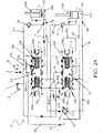
- valve structure according to the present invention is globally and schematically indicated with 1.
- the valve structure 1 of the present invention is applied to drive hydraulic cylinders for aligning and rotating reversible ploughs, preferably multiple-furrow reversible ploughs.
- the valve structure 1 comprises a body 2 adapted to receive and house the work-fluid, for instance hydraulic oil.
- the body 2 includes the main components of the valve structure 1.
- the body 2 of the valve structure 1 is made of zinc-plated steel and the internal components are made of hardened and ground steel, even if other suitable materials can be used and the present invention is not limited by the materials used.
- the alignment cylinder is retracted, and the overturning cylinder is extended.
- This operating configuration can be automatically obtained by a working sequence of the valve structure 1 which is disclosed in the following.
- the valve structure 1 of the present invention also enables a reverse configuration of the plough movement, which is started for instance after adjusting mechanical components of the plough.
- the valve structure 1 comprises a first port 3 which is adapted to receive the work-fluid from a pump P, and a second port 4 adapted to be in fluid communication with the tank T.
- the first port 3 can be called input port and the second port 4 can be called return port.
- the body 2 of the valve structure 1 includes a first seat 5 and a second seat 6 which extend longitudinally along a longitudinal axis H-H. More in particular, the first seat 5 and the second seat 6 extend along respective longitudinal axis H-H which are substantially parallel to each other.
- first seat 5 and the second seat 6 comprise a respective cavity closed axially by respective closure bodies 15 (such as suitable plugs).
- the first seat 5 comprises a plurality of containment chambers (herein indicated with references 5a, 5b, 5c, 5d, 5e, 5f, 5g) arranged side by side
- the second seat comprises a plurality of corresponding containment chambers (herein indicated with references (6a, 6b, 6c, 6d, 6e, 6f, 6g) arranged side by side, said containment chambers being adapted to receive the work-fluid and being in a selective fluid communication with each other due to the presence of two spools in the seats 5 and 6, as it will be disclosed in the following.
- Each step of the working sequence of the valve structure 1 corresponds to different containment chamber housing the work-fluid.
- the containment chambers have an annular shape.
- the containment chambers of the first seat 5 include a first end containment chamber 5a and a second end containment chamber 5b opposed to each other along the longitudinal axis H-H of said first seat 5, and the containment chambers of the second seat 6 include a first end containment chamber 6a and a second end containment chamber 6b opposed to each other along the longitudinal axis H-H of said second seat 6.
- the first seat 5 extends between the first and second end containment chambers 5a and 5b
- the second seat 6 extends between the first and second end containment chambers 6a and 6b along the longitudinal axis H-H.
- the first seat 5 comprises a central containment chamber 5c and intermediate containment chambers 5d, 5e, 5f, 5g, said intermediate containment chambers being arranged between the end containment chambers 5a, 5b and the central containment chamber 5c.
- the second seat 6 comprises a central containment chamber 6c and intermediate containment chambers 6d, 6e, 6f, 6g said intermediate containment chambers being arranged between the end containment chambers 6a, 6b and the central containment chamber 6c.
- the first seat 5 is connected to the first port 3, in particular through the central containment chamber 5c.
- the valve structure 1 is able to control the movement of two hydraulic cylinders of a reversible plough: a first hydraulic cylinder 10 for aligning the plough (also called alignment cylinder 10) and a second hydraulic cylinder 12 for rotating the plough (also called overturning cylinder 12).
- the valve structure 1 comprises a first interconnection port 7a for the connection of the valve structure 1 to a first chamber 10a of the first hydraulic cylinder 10, and a second interconnection port 7b for the connection to a second chamber 10b of said first hydraulic cylinder 10.
- the first chamber 10a is indicated also as head chamber 10a and the second chamber 10b is indicated also as rod chamber 10b.
- valve structure 1 comprises a third interconnection port 8a for the connection of said valve structure 1 to a first chamber 12a of the second hydraulic cylinder 12 for reversing the plough, and a fourth interconnection port 8b for the connection to a second chamber 12b of said second hydraulic cylinder 12.
- first chamber 12a is indicated also as head chamber 12a and the second chamber 12b is indicated also as rod chamber 12b.
- the operation of the first and second hydraulic cylinders 10 and 12 is precisely controlled and timed by a hydraulic sequencing circuit of the valve structure 1, said hydraulic sequencing circuit being configured to precisely control the flow path and pressure of the work-fluid.
- the hydraulic sequencing circuit comprises a relief valve 11 adapted to be in fluid communication with the first cylinder 10 and with the second cylinder 12.
- the valve structure 1 comprises a first duct 7' adapted to connect the first interconnection port 7a with the first seat 5 (in particular the intermediate chamber 5f thereof), a second duct 7" adapted to connect the second interconnection port 7b with the outlet 11o of the relief valve 11, a third duct 8' adapted to connect the third interconnection port 8a with the inlet 11i of said relief valve 11, and a forth duct 8" adapted to connect the fourth interconnection port 8b and the second seat 6 (in particular the intermediate chamber 6f thereof).
- a further duct 7''' is configured to connect the first interconnection port 7a and the return port 4
- a further duct 8''' is configured to connect the fourth interconnection port 8b and the return port 4.
- the valve structure 1 comprises a first connection duct 20 and a second connection duct 21 configured to connect portions of the first seat 5 and the second seat 6 to each other (in any case, another connection configuration may be adopted according to specific needs).
- the first connection duct 20 is arranged between the first end containment chamber 5a of the first seat 5 and the corresponding first end containment chamber 6a of the second seat 6 (i.e. the chambers on the left according to the reference system of the figures). Therefore, the portions of the first seat 5 and of the second seat 6 that are connected by the first connection duct 20 are the first end containment chambers 5a and 6a.
- the second connection duct 21 is arranged between one of the intermediate containment chambers of the first seat 5 (chamber 5e in the example of the figures) and the central containment chamber 6c of the second seat 6.
- a first spool (or selector) 13 and a second spool (or selector) 14 are slidably housed inside the first seat 5 and the second seat 6, respectively.
- the first spool 13 and second spool 14 are configured to control the work-fluid passage between the pump P, the first seat 5, the second seat 6, the first hydraulic cylinder 10, the second hydraulic cylinder 12 and the tank T, in order to control the actuation of said first hydraulic cylinder 10 and said second hydraulic cylinder 12 according to a precise work sequence for aligning and turning the plough.
- the sequencing circuit of the valve structure 1 is configured to control the movement of the spools 13 and 14 in order to define the flow path and fluid pressure suitable for executing the corresponding steps of the plough work sequence.
- the operational interconnection between the first seat 5 and the second seat 6 (and the other components of the valve structure 1) is thus controlled by the first spool 13 and the second spool 14, in particular by controlling the relative displacement thereof.
- the spools 13 and 14 comprise adjacent chambers (e.g. five chambers), each moving chamber determining a specific path of the work-fluid.
- the first spool 13 comprises two housing seats 18a and 18b at the opposite end thereof (e.g. opposed with respect to the longitudinal axis H-H), and the second spool 14 comprises two corresponding housing seats 19a and 19b at the opposite end thereof, said housing seats 18a-18b being shaped to house elastic members 22a-22b (such as springs) for controlling the movement of said first spool 13 and said housing seats 19a-19b being shaped to house elastic members 23a-23b (such as springs) for controlling the movement of said second spool 14.
- the housing seats 18 and 19 are in the form of an open recess in the spools 13 and 14 to house the elastic members 22a-22b and 23a-23b.
- valve structure 1 comprises elastic members 22a-22b and 23a-23b, usually comprising springs, acting between the body 2, and more particular the closure members 15, and the respective spool 13 and 14, and are configured to move said spools 13 and 14.
- the housing seats 18a-18b and 19a-19b are formed at the end chambers of the spools 13 and 14.
- the housing seats 18a and 18b of the first spool 13 are configured to receive the work-fluid from the end containment chambers 5a and 5b of the first seat 5, respectively, and the seats 19a and 19b of the second spool 14 are configured to receive the work-fluid from the end containment chambers 6a and 6b of the second seat 6, respectively.
- the housing seats 18a-18b and 19a-19b (which can be called also spring chambers) are in fluid communication with the respective end containment chambers of the first seat 5 and of the second seat 6, so that the work-fluid can be introduced in said housing seats 18a-18b and 19a-19b in order to cause a compression of the elastic members 22a-22b and 23a-23b when needed for moving the spools 13 and 14.
- the housing seats may not be present and the end containment chambers may act as spring chambers (i.e. the housing seats may be coincident with the end containment chambers), as well as other suitable configurations may be adopted.
- the valve structure 1 of the present invention further comprises a relief valve 24 arranged in a first return path (i.e. the duct 7''') of the work-fluid between the first chamber 10a of the first hydraulic cylinder 10 and the second port 4, which, in the first configuration of the plough, is connected to the tank T.
- a relief valve 24 arranged in a first return path (i.e. the duct 7''') of the work-fluid between the first chamber 10a of the first hydraulic cylinder 10 and the second port 4, which, in the first configuration of the plough, is connected to the tank T.
- valve structure 1 of the present invention comprises another relief valve, herein indicated with the reference 27, arranged in a second return path (i.e. the duct 8''') of the work-fluid between the second chamber 12b of the second hydraulic cylinder 12 and the second port 4.
- a second return path i.e. the duct 8'''
- ducts 7''' and 8''' may also be seen as different portions of a same return path of the valve structure 1.
- valve structure 1 The operation of the valve structure 1 according to the invention is as follows.
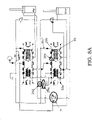
- the first spool 13 and the second spool 14 are at an initial neutral position (also called initial operating position) due to the action of the elastic members 22a-22b and 23a-23b (which maintain the spools 13 and 14 substantially in a central position in the respective seats 5 and 6).
- This neutral position of the spools 13 and 14 maintains the first hydraulic cylinder 10 retracted and the second hydraulic cylinder 12 extended, which, as seen before, corresponds to the working configuration of the plough.
- the hydraulic sequencing circuit of the valve structure 1 is suitably configured such that, when the operation of the machine is started and a first configuration is selected by the operator by acting on the tractor commands (i.e. the pump P is connected to the first port 3 by the distributor D), the working sequence leading to the rotation and alignment of the plough is activated.
- the work-fluid is supplied to the first port 3 from the pump P; in other words, the work-fluid is pumped into the first seat 5 via the first port 3.
- the initial neutral position of the spools 13 and 14 is such that the work-fluid flows to the first chamber 10a of the alignment cylinder 10 through the first spool 13 and the first interconnection port 7a in order to extend said first hydraulic cylinder 10.
- a first restrictor 26a is formed at the first spool 13, said first restrictor 26a being arranged and configured so that, when the first spool 13 and the second spool 14 are at the initial neutral position, the work-fluid from the pump P passes through said first restrictor 26a before entering the first chamber 10a of the first hydraulic cylinder 10, thus avoiding hydraulic shocks.
- the pump P is connected the head side 10a of the alignment cylinder 10 through the restrictor 26a on the first spool 13.
- the first restrictor 26a is made in the second chamber of the first spool 13 when counting from the left-end-side thereof.
- the first restrictor 26a is such that the work-fluid entering in the central containment chamber 5c of the first seat 5 can ooze toward the adjacent intermediate containment chamber 5f (which is connected to the first chamber 10a of the first hydraulic cylinder 10 via the first duct 7'), avoiding hydraulic shocks and sending a small amount of fluid in the first chamber 10a of the first hydraulic cylinder 10.
- the fluid is forced to flow into the first chamber 10a of the first hydraulic cylinder via the first restrictor 26a, suitably avoiding hydraulic shock and preventing the relief valve 24 from opening.
- the rod chamber 10a of the alignment cylinder 10 is connected to the outlet 11o of the relief valve 11, which has a large secondary area and a separate spring chamber.
- the secondary area of the relief valve 11 is configured in such a way that the work-fluid which is discharged from the rod chamber 10a of the alignment cylinder 10 passes through the second interconnection port 7b and then from the outlet 11o to the inlet 11i of said relief valve 11 before entering into the second spool 14.
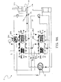
- the valve structure 1 comprises a second restrictor 26b arranged in the return path of the fluid discharged from the rod chamber 10b of the alignment cylinder 10 and leaving the second spool 14.
- the second restrictor 26b is arranged in parallel to the first connection duct 20 and configured to cause a pressure drop of the work-fluid passing therethrough and to cause a corresponding pressure increase in the portions of the first seat 5 and of the second seat 6 in fluid connection with said first connection duct 20.
- the work-fluid from the relief valve 11 passes through the second spool 14 and then through the second restrictor 26b, which is in fluid connection with the first end containment chamber 5a of the first seat 5 and with the first end containment chamber 6a of the second seat 6, and therefore in fluid connection with the respective housing seats 18a and 19a housing the spring members 22a and 23a.
- the pressure drop across this second restrictor 26b causes the pressure in spring chambers to increase, leading to a displacement of the first spool 13 and of the second spool 14.
- the pressure exerted by the return flow that is flowing towards the second port 4 is such that the first spool 13 and the second spool 14 are moved from their neutral position by the work-fluid supplied in the spring chambers (e.g. they are moved to the right according to the reference system of the figures).
- This new relative position of the first spool 13 and the second spool 14 enables the work-fluid from the pump P to be supplied toward the first chamber 10a of the first hydraulic cylinder 10 through the first spool 13 without passing through the first restrictor 26a.
- the displacement of the first spool 13 thus removes the first restrictor 26a from the flow path; even more particularly, as shown in figure 3B , the work-fluid passes through the left-end chamber of the first spool 13.
- the position of the second spool 14 is such that the return flow no longer has to pass only through the second restrictor 26b and can now pass also through the return duct Ret, which directly connects the intermediate containment chamber 6d of the second seat 6 and the return port 4 (the return duct Ret is then connected with the other return ducts 7''' and 8''', which in this step are not used due to the presence of the relief valves 24 and 27, which are still closed).
- the return ducts 7"', 8''' and Ret may be seen as portions of a same return duct of the valve structure 1.
- this position of the second spool 14 is such to open the passage RetP on said second spool 14 (which was closed in the initial neutral position of the second spool 14), allowing the work-fluid to flow from the second spool 14 into the return duct Ret towards the tank T.
- This configuration achieves a force balance to maintain the second spool 14 in this position.
- the alignment cylinder 10 now moves at full speed.
- the second hydraulic cylinder 12 does not move because the position of the first spool 13 does not allow the work-fluid to pass through the second connection duct 21, and therefore the work-fluid does not enter into the second seat 6 and the second spool 14, and thus does not enter into the second hydraulic cylinder 12.
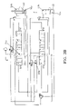
- the alignment cylinder 10 then reaches the end of stroke, as shown in figures 4A and 4B .
- no pressurized fluid flows in the first connection duct 20 and the pressure at the corresponding ends of the first spool 13 and second spool 14 (i.e. in the housing seats 18a and 19a connected with the end containment chambers 5a and 6a) decreases so that both spools 13 and 14 move from the right to a central position, i.e. they moves towards the initial neutral position (as better shown in figure 4B ), in which position the work-fluid cannot pass from the first seat 5 to the second seat 6 and is directed only into the first chamber 10a of the first hydraulic cylinder 10.
- the pressure in said first chamber 10a of said first hydraulic cylinder 10 increases and opens the relief valve 24, said relief valve 24 being thus configured such that, when the first hydraulic cylinder 10 reaches the end of the stroke and no fluid is discharged from the second chamber 10b thereof, it is in an open state.
- the valve structure 1 further comprises a third restrictor 26c which, in the first configuration, is arranged in the return path 7''' between the second port 4 and the relief valve 24 and is connected to the first seat 5 via a duct Du.
- This third restrictor 26c is configured to cause a pressure drop of the work-fluid passing therethrough and to cause a corresponding pressure increase in a portion of the first seat 5 in fluid connection with said third restrictor 26c.
- the portion of the first seat 5 in fluid connection with said third restrictor 26c is the second end containment chamber 5b, the third restrictor 26c being configured in such a way that the pressure of the work-fluid in said second end containment chamber 5b is increased to cause a corresponding pressure increase in the housing seat 18b of the first spool 13 and thus to cause the movement of said first spool 13.
- the relief valve 24 is opened, the work-fluid passes through the third restrictor 26c, which increases the pressure at the second end containment chamber 5b of the first seat 5, shifting the first spool 13 to the left.
- the displacement of the first spool 13 caused by the presence of the third restrictor 26c is opposite with respect to the displacement caused by the second restrictor 26b.
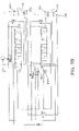
- This new displacement of the spool 13 enables the work-fluid to flow from the pump P, to the first spool 13, then to the second spool 14 (via the third chamber thereof when counting from the left-end side) and then to second chamber 12b of the second hydraulic cylinder 12, whose rod begins to be retracted.
- the passage Pass (highlighted in figures 5A and 5B ) on said first spool 13 is opened and the work-fluid can pass via said passage Pass and then to flow into the second spool 14.
- the passage Pass is formed in the fourth chamber of the first spool 13 (counting from the left end side) and the work-fluid flows through the left end chamber of the second spool 14.
- said first spool 13 comprises a restrictor 28a configured to provide the proper timing to allow this position to be maintained, so that the work-fluid can still flow from the pump P, then pass through the first spool 13, the second spool 14, and finally be supplied to the second chamber 12b of the second hydraulic cylinder 12.
- the notch 28a is in the form of a small restrictor formed in the chamber of the first spool 13 where the passage Pass is also present, so that a small amount of fluid can be delivered from said passage Pass to the duct Du which is in turn connected with the housing seat 18b of the elastic member 22b of said first spool 13, in order to exert a counterpressure.
- this notch 28a is dimensioned in such a way that it has the timing to allow the spool 14 to maintain the current position without causing an excessive pressure drop.
- the notch 28a allows the work-fluid to flow across it, thus maintaining a flow through the third restrictor 26c so that the pressure in the housing seat 18b is equal to the pressure in the housing seat 18a plus the force of the elastic member 22a (e.g. less than 10 bar).
- the sequencing hydraulic causes the first spool 13 and the second spool 14 to be displaced relative to each other so that the work-fluid is allowed to pass via the second connection duct 21 from the first spool 13 to the second spool 14 and then to the second chamber 12b of the second hydraulic cylinder 12, whose rod is thus retracted.
- the overturning cylinder 12 then reaches the end of stroke, corresponding to a 90° rotation of the plough.
- the pressure in the rod chamber 12b increases until it opens relief valve 27.
- the relief valve 27 is thus configured in such a way that, when the second hydraulic cylinder 12 reaches the end of the stroke and no fluid is displaced from the first chamber 10b thereof, it is in an open state.
- the valve structure 1 further comprises a fourth restrictor 26d which is arranged in the return path between the second port 4 and the relief valve 27 and is configured to cause a pressure drop of the work-fluid passing therethrough and to cause a pressure increase in a corresponding portion of the second seat 6 in fluid connection with said fourth restrictor 26d.
- the portion of the second seat 6 receiving the pressurized fluid is the second end containment chamber 6b of said second seat 6 and the fourth restrictor 26d is configured in such a way that the pressure of the work-fluid in said second end containment chamber 6b is increased to cause the movement of the second spool 14.
- the pressurized fluid is delivered to the end containment chamber of the second seat 6 by a further duct Du" connected to said end containment chamber.
- the second spool 14 is thus configured to be moved by the work-fluid in the end containment chamber 6b in an opposite direction than the motion caused by the second restrictor 26b (i.e. it is shifted all to the left), allowing the work-fluid to flow from the pump P, through the first spool 13 (which remains in its previous position) to the first chamber 12a of the second hydraulic cylinder 12, which thus reverse its stroke, while the first hydraulic cylinder 10 does not move due to the presence of the relief valve 11.
- the relief valve 27 opens, therefore passing flow through the fourth restrictor 26d and increasing the pressure where the elastic member 23b is, so that the spool 14 shifts to the left.
- the first spool 13 and the second spool 14 are displaced relative to each other so that the work-fluid from the pump P is allowed to pass via the second connection duct 21 from the first spool 13 to the second spool 14 and then it is delivered into the first chamber 12a of the second hydraulic cylinder 12, whose rod is extending.
- the pump flow is now directed to the head chamber 12a of the overturning cylinder 12.
- the return flow from that cylinder passes again through the fourth restrictor 26d.
- the valve structure 1 further comprises a check valve 29a arranged in parallel to the fourth restrictor 26d and configured to allow the passage of the return flow for pressure values ranging from 3 to 10 bar, preferably 4 bar. Therefore, return flow from the second hydraulic cylinder 12 directed to the second port 4 passes again through the fourth restrictor 26d and the check valve 29a, which has an opening pressure (due to its spring) sufficient to hold the second spool 14 in the left position.
- the presence of the check valve 29a reduces excessive pressure drops due to the restrictor.
- the overturn cylinder 12 then reaches the end of stroke.
- the flow through the fourth restrictor 26d and check valve 29a decreases, leading to a pressure reduction at the second end containment chamber 6b of the second seat 6, i.e. where the elastic member 23b is.
- the second spool 14 then starts to move to the right (reaching an intermediate position), so that the work-fluid can flow from the pump P through the first spool 13, through the second spool 14, towards the first chamber 12a of the second hydraulic cylinder 12.
- a notch 28b which is formed on said second spool 14 opens. More in particular, the notch 28b (which is formed for example in the fourth chamber of the second spool 14 when counting from the left-end side) enables a small amount of fluid to flow in the further duct Du" and then into the second end chamber 6a. This notch 28b is thus configured to provide the proper timing to allow said second spool 14 to maintain the above-mentioned intermediate position allowing the work-fluid to flow from the pump P through the first spool 13 and the second spool 14 towards the first chamber 12a of the second hydraulic cylinder 12.
- the pressure on the head chamber 12a of the overturning cylinder 12 then increases until it opens the relief valve 11. This allows the flow to reach the rod side 10b of the alignment cylinder 10 to complete the alignment of the plough.
- the relief valve 11 has a calibration pressure comprises between 90 bar and 200 bar, preferably between 120 bar and 140 bar.
- the rod side pressure of the alignment cylinder 10 holds the relief valve 11 open (due to its large secondary area).
- the pressurized work-fluid in thus introduced from the relief valve 11 into the second chamber 10b of the alignment cylinder, which retracts to align the plough and bring it in the working position. Therefore, the secondary area of the relief valve 11 is configured so that the pressure in the second chamber 10b of the first hydraulic cylinder 10 holds said relief valve 11 opened.
- the return flow from the alignment cylinder passes again through the third restrictor 26c which, as seen before is arranged in the return path between the first spool 13 and the tank T.
- the valve structure 1 further comprises a check valve 29b arranged in parallel to the third restrictor 26c and configured to allow the passage of the return flow for pressure values ranging from 2 to 10 bar, preferably 8 bar (i.e. the check valve 29b has an opening pressure of 10 bar due to its spring).
- the return flow from the alignment cylinder 10 passes through the third restrictor 26c until the pressure of 10 bar is reached, at which point check valve 29b opens.
- the alignment cylinder 10 can fully retract. At this point, the turning and the successive alignment of the plough is complete.
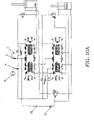
- the operator will start the cycle but stops part of the way through.
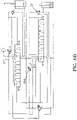
- An example of when this occurs is during the plough setup, when the overturning mechanism has to be lifted from its mechanical stops to allow for these to be adjusted. In this case the operator has carried out the first alignment, and part of the overturning cycle, as shown in figures 10A and 10B .
- the working tools have to be raised, which is performed by operating the plough as disclosed previously in the normal operation; after maintenance, the plough has to be taken in the original position, i.e. by means of an inverse movement thereof.
- the alignment cylinder 10 is fully extended and the overturning cylinder 12 is partially retracted.
- the operator has to take the plough into its original position, and therefore he selects the spool control valve in the opposite direction (e.g., with reference to figure 1 , he selects the distributor D in the crossed configuration, so that the inverse configuration is activated).
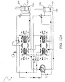
- the pump and tank connection are swapped on the valve.
- the operator can act on the command and switch the pump P and the tank T in order to switch from the first configuration to the second reverse configuration.
- the first port 3 is connected with the tank T and the second port 4 is connected to the pump P.
- valve structure 1 comprises a third connection duct 30 adapted to connect the second hydraulic cylinder 12, in particular the second chamber 12b thereof, and the tank T in the second reversed configuration.
- the valve structure 1 comprises a check valve 31 arranged in the third connection duct 30 and configured to allow the work-fluid to flow from second chamber 12b of the second hydraulic cylinder 12 to the tank T in the second reversed configuration of the plough and to block the work-fluid in the first configuration of the plough.
- the hydraulic sequencing circuit is configured such that, in this second reversed configuration, when the work-fluid is fed to the first port 3, it flows to the head chamber 12a of the second hydraulic cylinder 12 and then the work-fluid exiting from the rod chamber 12b passes through the third connection duct 30 (which is part of the return path in this second configuration) via the check valve 31 and then returns to the tank T.
- the check valve 31 blocks the fluid in the first configuration, and enables the fluid passage only in the secondo reversed configuration, so that the addition of the third connection duct 30 does not affect the normal operation of the plough.
- the work-fluid from the pump P passes through the second restrictor 26b. This reduces the pressure where the elastic member 23a is.
- the second spool 14 is thus slightly moved to the left until the passage Pass' on the second spool 14 opens.
- the second spool timing in passage Pass' is specifically selected to allow the reversing function to work.
- valve 11 opens and the flow passes to the rod chamber 10b of the alignment cylinder 10 to bring the plough to the proper working position.
- figure 13 is a side elevation view of a reversible plough driven by the valve structure 1 of the present invention, said plough being indicated with the reference number 40.
- the plough 40 is equipped with the abovementioned cylinders 10 and 12, whose chambers are connected to ports the 7a, 7b, 8a, and 8b of the valve structure, as disclosed above.
- the present invention provides a valve structure for driving the hydraulic cylinders of a reversible plough to obtain the automatic oil backflow and therefore the automatic reversal of the movement of said cylinders.
- the alignment cylinder and the overturning cylinder work in parallel. First the alignment cylinder starts lining up the load, and then the overturning cylinder starts rotating the plough. Once it passed the standoff position (i.e. 90°), the movement of the cylinders is inverted.
- the proper working sequence is ensured by the presence of two moving spools whose relative position determines a particular flow path of the work-fluid: therefore, a particular relative position of the spools corresponds to a particular step in the working sequence.
- the relative position of the spools is determined by a suitably designed hydraulic circuit, which is configured to control the work-fluid flow and pressure at specific locations of the valve structure for moving the spools, wherein the specific working sequence is controlled by the presence of relief valves in the hydraulic circuit whose opening or closure determines a specific flow path and thus the execution of a particular step in the working sequence.
- the presence of a check valve arranged between the pump/tank and the overturning cylinder enables a safe reverse operation of the plough.
- a reliable actuation valve structure for the rotation and alignment of reversible plows is provided, this valve structure allowing to control, in sequence, the alignment cylinder and the overturning cylinder, also ensuring the reverse operation of the plough.
- the steps of the working sequence are executed automatically due to the proper arrangement of the hydraulic components.
- the valve structure comprises hydraulic components configured to control the relative displacement of the spools to automatically control the movement of the cylinders.
- a check valve then enables the fluid to flow in the second reversed configuration of the plough.
- the reverse operation is possible thanks to the check valve in the return path, allowing a larger number of applications of this valve structure.
- This reverse operation is very useful, for example for maintenance of the plough tools, and is achieved in very simple and effective way.
- the disclosed valve structure has low production cost and it is easy to manufacture.
Landscapes
- Engineering & Computer Science (AREA)
- Mechanical Engineering (AREA)
- General Engineering & Computer Science (AREA)
- Physics & Mathematics (AREA)
- Fluid Mechanics (AREA)
- Life Sciences & Earth Sciences (AREA)
- Soil Sciences (AREA)
- Environmental Sciences (AREA)
- Chemical & Material Sciences (AREA)
- Analytical Chemistry (AREA)
- Fluid-Pressure Circuits (AREA)
Priority Applications (3)
| Application Number | Priority Date | Filing Date | Title |
|---|---|---|---|
| EP20425053.4A EP4006361B1 (de) | 2020-11-25 | 2020-11-25 | Verbesserte ventilstruktur zum antrieb von drehpflügen |
| US17/531,973 US11754098B2 (en) | 2020-11-25 | 2021-11-22 | Valve structure for driving reversible ploughs |
| CN202111426049.XA CN114607659A (zh) | 2020-11-25 | 2021-11-24 | 用于驱动可翻转犁的改进的阀结构 |
Applications Claiming Priority (1)
| Application Number | Priority Date | Filing Date | Title |
|---|---|---|---|
| EP20425053.4A EP4006361B1 (de) | 2020-11-25 | 2020-11-25 | Verbesserte ventilstruktur zum antrieb von drehpflügen |
Publications (3)
| Publication Number | Publication Date |
|---|---|
| EP4006361A1 true EP4006361A1 (de) | 2022-06-01 |
| EP4006361B1 EP4006361B1 (de) | 2023-12-20 |
| EP4006361C0 EP4006361C0 (de) | 2023-12-20 |
Family
ID=74180923
Family Applications (1)
| Application Number | Title | Priority Date | Filing Date |
|---|---|---|---|
| EP20425053.4A Active EP4006361B1 (de) | 2020-11-25 | 2020-11-25 | Verbesserte ventilstruktur zum antrieb von drehpflügen |
Country Status (3)
| Country | Link |
|---|---|
| US (1) | US11754098B2 (de) |
| EP (1) | EP4006361B1 (de) |
| CN (1) | CN114607659A (de) |
Cited By (1)
| Publication number | Priority date | Publication date | Assignee | Title |
|---|---|---|---|---|
| EP4544890A1 (de) * | 2023-10-27 | 2025-04-30 | Amazonen-Werke H. Dreyer SE & Co. KG | Anbaudrehpflug für eine zugmaschine sowie verfahren zu dessen steuerung |
Citations (2)
| Publication number | Priority date | Publication date | Assignee | Title |
|---|---|---|---|---|
| EP0890748A1 (de) * | 1997-07-10 | 1999-01-13 | Kuhn-Huard S.A. | Steuereinrichtung für einen Pflug |
| CN108679022A (zh) * | 2018-05-18 | 2018-10-19 | 宁波真格液压科技有限公司 | 一种双缸控制系统 |
Family Cites Families (1)
| Publication number | Priority date | Publication date | Assignee | Title |
|---|---|---|---|---|
| CN108547814B (zh) * | 2018-05-18 | 2019-12-24 | 江苏南京白马现代农业高新技术产业园有限公司 | 一种多路阀装置 |
-
2020
- 2020-11-25 EP EP20425053.4A patent/EP4006361B1/de active Active
-
2021
- 2021-11-22 US US17/531,973 patent/US11754098B2/en active Active
- 2021-11-24 CN CN202111426049.XA patent/CN114607659A/zh active Pending
Patent Citations (2)
| Publication number | Priority date | Publication date | Assignee | Title |
|---|---|---|---|---|
| EP0890748A1 (de) * | 1997-07-10 | 1999-01-13 | Kuhn-Huard S.A. | Steuereinrichtung für einen Pflug |
| CN108679022A (zh) * | 2018-05-18 | 2018-10-19 | 宁波真格液压科技有限公司 | 一种双缸控制系统 |
Cited By (1)
| Publication number | Priority date | Publication date | Assignee | Title |
|---|---|---|---|---|
| EP4544890A1 (de) * | 2023-10-27 | 2025-04-30 | Amazonen-Werke H. Dreyer SE & Co. KG | Anbaudrehpflug für eine zugmaschine sowie verfahren zu dessen steuerung |
Also Published As
| Publication number | Publication date |
|---|---|
| US20220163055A1 (en) | 2022-05-26 |
| EP4006361B1 (de) | 2023-12-20 |
| CN114607659A (zh) | 2022-06-10 |
| EP4006361C0 (de) | 2023-12-20 |
| US11754098B2 (en) | 2023-09-12 |
Similar Documents
| Publication | Publication Date | Title |
|---|---|---|
| DE68912305T2 (de) | Fluid-steuerungsmechanismus für kraftschaufeln. | |
| CN101563542B (zh) | 转动致动电液阀 | |
| US7204084B2 (en) | Hydraulic system having a pressure compensator | |
| WO2008150386A1 (en) | Hydraulic system having an external pressure compensator | |
| DE102006012733A1 (de) | Fast cam phaser-Hydraulikkreis, insbesondere für Nockenwellenversteller, und entsprechendes Steuerelement | |
| US20060243128A1 (en) | Hydraulic system having a pressure compensator | |
| PL131095B1 (en) | Hydraulic percussive machine,especially mining drill | |
| EP4006361B1 (de) | Verbesserte ventilstruktur zum antrieb von drehpflügen | |
| US8479504B2 (en) | Hydraulic system having an external pressure compensator | |
| DE102006007783A1 (de) | Elektrohydraulisches Bereitschaftslenkungssystem | |
| WO2007087962A1 (de) | Hydraulische steueranordnung mit regeneration | |
| WO2008058584A1 (de) | Hydraulisches zweikreissystem und zusammenschaltventilanordnung | |
| KR102491222B1 (ko) | 작업차용 작업기 승강 및 플로팅 구현을 위한 유압회로 | |
| DE19718294A1 (de) | Hydraulischer Schwingungserzeuger | |
| US12291848B2 (en) | Flow control valve | |
| DE102008064139A1 (de) | Hydraulische Steueranordnung | |
| DE102015015807A1 (de) | Hydraulikhammer mit variabler Hubsteuerung | |
| RU2839584C2 (ru) | Клапанная конструкция для приведения в действие оборотных плугов | |
| EP0758718A1 (de) | Vorrichtung zum Verdrehen eines Pfluges | |
| DE112004002298T5 (de) | Hydraulische Schlagvorrichtung | |
| DE102005059238B4 (de) | Steuerventileinrichtung zur Steuerung eines Verbrauchers | |
| US7243493B2 (en) | Valve gradually communicating a pressure signal | |
| KR20200050588A (ko) | 수동 절환식 플로팅 밸브 | |
| DE4403213A1 (de) | Einrichtung zur Antriebssteuerung einer Zweizylinder-Dickstoffpumpe | |
| EP0384888B1 (de) | Bohrvorrichtung |
Legal Events
| Date | Code | Title | Description |
|---|---|---|---|
| PUAI | Public reference made under article 153(3) epc to a published international application that has entered the european phase |
Free format text: ORIGINAL CODE: 0009012 |
|
| STAA | Information on the status of an ep patent application or granted ep patent |
Free format text: STATUS: THE APPLICATION HAS BEEN PUBLISHED |
|
| AK | Designated contracting states |
Kind code of ref document: A1 Designated state(s): AL AT BE BG CH CY CZ DE DK EE ES FI FR GB GR HR HU IE IS IT LI LT LU LV MC MK MT NL NO PL PT RO RS SE SI SK SM TR |
|
| STAA | Information on the status of an ep patent application or granted ep patent |
Free format text: STATUS: REQUEST FOR EXAMINATION WAS MADE |
|
| 17P | Request for examination filed |
Effective date: 20221130 |
|
| RBV | Designated contracting states (corrected) |
Designated state(s): AL AT BE BG CH CY CZ DE DK EE ES FI FR GB GR HR HU IE IS IT LI LT LU LV MC MK MT NL NO PL PT RO RS SE SI SK SM TR |
|
| REG | Reference to a national code |
Ref country code: DE Ref legal event code: R079 Free format text: PREVIOUS MAIN CLASS: F15B0013000000 Ipc: F15B0013080000 Ref document number: 602020023016 Country of ref document: DE |
|
| RIC1 | Information provided on ipc code assigned before grant |
Ipc: F15B 13/08 20060101AFI20230512BHEP |
|
| GRAP | Despatch of communication of intention to grant a patent |
Free format text: ORIGINAL CODE: EPIDOSNIGR1 |
|
| STAA | Information on the status of an ep patent application or granted ep patent |
Free format text: STATUS: GRANT OF PATENT IS INTENDED |
|
| INTG | Intention to grant announced |
Effective date: 20230629 |
|
| GRAS | Grant fee paid |
Free format text: ORIGINAL CODE: EPIDOSNIGR3 |
|
| GRAA | (expected) grant |
Free format text: ORIGINAL CODE: 0009210 |
|
| STAA | Information on the status of an ep patent application or granted ep patent |
Free format text: STATUS: THE PATENT HAS BEEN GRANTED |
|
| AK | Designated contracting states |
Kind code of ref document: B1 Designated state(s): AL AT BE BG CH CY CZ DE DK EE ES FI FR GB GR HR HU IE IS IT LI LT LU LV MC MK MT NL NO PL PT RO RS SE SI SK SM TR |
|
| REG | Reference to a national code |
Ref country code: GB Ref legal event code: FG4D |
|
| REG | Reference to a national code |
Ref country code: CH Ref legal event code: EP |
|
| REG | Reference to a national code |
Ref country code: DE Ref legal event code: R096 Ref document number: 602020023016 Country of ref document: DE |
|
| REG | Reference to a national code |
Ref country code: IE Ref legal event code: FG4D |
|
| U01 | Request for unitary effect filed |
Effective date: 20240118 |
|
| U07 | Unitary effect registered |
Designated state(s): AT BE BG DE DK EE FI FR IT LT LU LV MT NL PT SE SI Effective date: 20240126 |
|
| PG25 | Lapsed in a contracting state [announced via postgrant information from national office to epo] |
Ref country code: GR Free format text: LAPSE BECAUSE OF FAILURE TO SUBMIT A TRANSLATION OF THE DESCRIPTION OR TO PAY THE FEE WITHIN THE PRESCRIBED TIME-LIMIT Effective date: 20240321 |
|
| PG25 | Lapsed in a contracting state [announced via postgrant information from national office to epo] |
Ref country code: ES Free format text: LAPSE BECAUSE OF FAILURE TO SUBMIT A TRANSLATION OF THE DESCRIPTION OR TO PAY THE FEE WITHIN THE PRESCRIBED TIME-LIMIT Effective date: 20231220 |
|
| PG25 | Lapsed in a contracting state [announced via postgrant information from national office to epo] |
Ref country code: GR Free format text: LAPSE BECAUSE OF FAILURE TO SUBMIT A TRANSLATION OF THE DESCRIPTION OR TO PAY THE FEE WITHIN THE PRESCRIBED TIME-LIMIT Effective date: 20240321 Ref country code: ES Free format text: LAPSE BECAUSE OF FAILURE TO SUBMIT A TRANSLATION OF THE DESCRIPTION OR TO PAY THE FEE WITHIN THE PRESCRIBED TIME-LIMIT Effective date: 20231220 |
|
| PG25 | Lapsed in a contracting state [announced via postgrant information from national office to epo] |
Ref country code: RS Free format text: LAPSE BECAUSE OF FAILURE TO SUBMIT A TRANSLATION OF THE DESCRIPTION OR TO PAY THE FEE WITHIN THE PRESCRIBED TIME-LIMIT Effective date: 20231220 Ref country code: NO Free format text: LAPSE BECAUSE OF FAILURE TO SUBMIT A TRANSLATION OF THE DESCRIPTION OR TO PAY THE FEE WITHIN THE PRESCRIBED TIME-LIMIT Effective date: 20240320 Ref country code: HR Free format text: LAPSE BECAUSE OF FAILURE TO SUBMIT A TRANSLATION OF THE DESCRIPTION OR TO PAY THE FEE WITHIN THE PRESCRIBED TIME-LIMIT Effective date: 20231220 |
|
| PG25 | Lapsed in a contracting state [announced via postgrant information from national office to epo] |
Ref country code: IS Free format text: LAPSE BECAUSE OF FAILURE TO SUBMIT A TRANSLATION OF THE DESCRIPTION OR TO PAY THE FEE WITHIN THE PRESCRIBED TIME-LIMIT Effective date: 20240420 |
|
| PG25 | Lapsed in a contracting state [announced via postgrant information from national office to epo] |
Ref country code: CZ Free format text: LAPSE BECAUSE OF FAILURE TO SUBMIT A TRANSLATION OF THE DESCRIPTION OR TO PAY THE FEE WITHIN THE PRESCRIBED TIME-LIMIT Effective date: 20231220 |
|
| PG25 | Lapsed in a contracting state [announced via postgrant information from national office to epo] |
Ref country code: SK Free format text: LAPSE BECAUSE OF FAILURE TO SUBMIT A TRANSLATION OF THE DESCRIPTION OR TO PAY THE FEE WITHIN THE PRESCRIBED TIME-LIMIT Effective date: 20231220 |
|
| PG25 | Lapsed in a contracting state [announced via postgrant information from national office to epo] |
Ref country code: SM Free format text: LAPSE BECAUSE OF FAILURE TO SUBMIT A TRANSLATION OF THE DESCRIPTION OR TO PAY THE FEE WITHIN THE PRESCRIBED TIME-LIMIT Effective date: 20231220 Ref country code: SK Free format text: LAPSE BECAUSE OF FAILURE TO SUBMIT A TRANSLATION OF THE DESCRIPTION OR TO PAY THE FEE WITHIN THE PRESCRIBED TIME-LIMIT Effective date: 20231220 Ref country code: RO Free format text: LAPSE BECAUSE OF FAILURE TO SUBMIT A TRANSLATION OF THE DESCRIPTION OR TO PAY THE FEE WITHIN THE PRESCRIBED TIME-LIMIT Effective date: 20231220 Ref country code: IS Free format text: LAPSE BECAUSE OF FAILURE TO SUBMIT A TRANSLATION OF THE DESCRIPTION OR TO PAY THE FEE WITHIN THE PRESCRIBED TIME-LIMIT Effective date: 20240420 Ref country code: CZ Free format text: LAPSE BECAUSE OF FAILURE TO SUBMIT A TRANSLATION OF THE DESCRIPTION OR TO PAY THE FEE WITHIN THE PRESCRIBED TIME-LIMIT Effective date: 20231220 |
|
| PG25 | Lapsed in a contracting state [announced via postgrant information from national office to epo] |
Ref country code: PL Free format text: LAPSE BECAUSE OF FAILURE TO SUBMIT A TRANSLATION OF THE DESCRIPTION OR TO PAY THE FEE WITHIN THE PRESCRIBED TIME-LIMIT Effective date: 20231220 |
|
| PG25 | Lapsed in a contracting state [announced via postgrant information from national office to epo] |
Ref country code: PL Free format text: LAPSE BECAUSE OF FAILURE TO SUBMIT A TRANSLATION OF THE DESCRIPTION OR TO PAY THE FEE WITHIN THE PRESCRIBED TIME-LIMIT Effective date: 20231220 |
|
| REG | Reference to a national code |
Ref country code: DE Ref legal event code: R097 Ref document number: 602020023016 Country of ref document: DE |
|
| PLBE | No opposition filed within time limit |
Free format text: ORIGINAL CODE: 0009261 |
|
| STAA | Information on the status of an ep patent application or granted ep patent |
Free format text: STATUS: NO OPPOSITION FILED WITHIN TIME LIMIT |
|
| 26N | No opposition filed |
Effective date: 20240923 |
|
| U20 | Renewal fee for the european patent with unitary effect paid |
Year of fee payment: 5 Effective date: 20241113 |
|
| REG | Reference to a national code |
Ref country code: CH Ref legal event code: PL |
|
| PG25 | Lapsed in a contracting state [announced via postgrant information from national office to epo] |
Ref country code: MC Free format text: LAPSE BECAUSE OF FAILURE TO SUBMIT A TRANSLATION OF THE DESCRIPTION OR TO PAY THE FEE WITHIN THE PRESCRIBED TIME-LIMIT Effective date: 20231220 |
|
| REG | Reference to a national code |
Ref country code: CH Ref legal event code: PL |
|
| GBPC | Gb: european patent ceased through non-payment of renewal fee |
Effective date: 20241125 |
|
| PG25 | Lapsed in a contracting state [announced via postgrant information from national office to epo] |
Ref country code: CH Free format text: LAPSE BECAUSE OF NON-PAYMENT OF DUE FEES Effective date: 20241130 |
|
| PG25 | Lapsed in a contracting state [announced via postgrant information from national office to epo] |
Ref country code: GB Free format text: LAPSE BECAUSE OF NON-PAYMENT OF DUE FEES Effective date: 20241125 |
|
| PG25 | Lapsed in a contracting state [announced via postgrant information from national office to epo] |
Ref country code: IE Free format text: LAPSE BECAUSE OF NON-PAYMENT OF DUE FEES Effective date: 20241125 |
|
| U20 | Renewal fee for the european patent with unitary effect paid |
Year of fee payment: 6 Effective date: 20251111 |
|
| PG25 | Lapsed in a contracting state [announced via postgrant information from national office to epo] |
Ref country code: HU Free format text: LAPSE BECAUSE OF FAILURE TO SUBMIT A TRANSLATION OF THE DESCRIPTION OR TO PAY THE FEE WITHIN THE PRESCRIBED TIME-LIMIT; INVALID AB INITIO Effective date: 20201125 |
|
| PG25 | Lapsed in a contracting state [announced via postgrant information from national office to epo] |
Ref country code: CY Free format text: LAPSE BECAUSE OF FAILURE TO SUBMIT A TRANSLATION OF THE DESCRIPTION OR TO PAY THE FEE WITHIN THE PRESCRIBED TIME-LIMIT; INVALID AB INITIO Effective date: 20201125 |