EP0890760A2 - Leistungsgetriebe mit komprimiertem, elastischem Ringelement zwischen äusserem Ring und innerer Narbe - Google Patents
Leistungsgetriebe mit komprimiertem, elastischem Ringelement zwischen äusserem Ring und innerer Narbe Download PDFInfo
- Publication number
- EP0890760A2 EP0890760A2 EP98112655A EP98112655A EP0890760A2 EP 0890760 A2 EP0890760 A2 EP 0890760A2 EP 98112655 A EP98112655 A EP 98112655A EP 98112655 A EP98112655 A EP 98112655A EP 0890760 A2 EP0890760 A2 EP 0890760A2
- Authority
- EP
- European Patent Office
- Prior art keywords
- power transmission
- transmission mechanism
- elastic member
- ring
- outer ring
- Prior art date
- Legal status (The legal status is an assumption and is not a legal conclusion. Google has not performed a legal analysis and makes no representation as to the accuracy of the status listed.)
- Granted
Links
- 230000005540 biological transmission Effects 0.000 title claims abstract description 61
- 230000007246 mechanism Effects 0.000 title claims description 45
- 238000006243 chemical reaction Methods 0.000 claims description 7
- 230000008602 contraction Effects 0.000 description 14
- 238000000034 method Methods 0.000 description 7
- 230000008569 process Effects 0.000 description 3
- 230000008878 coupling Effects 0.000 description 2
- 238000010168 coupling process Methods 0.000 description 2
- 238000005859 coupling reaction Methods 0.000 description 2
- 238000004073 vulcanization Methods 0.000 description 2
- 229910000639 Spring steel Inorganic materials 0.000 description 1
- 239000000853 adhesive Substances 0.000 description 1
- 230000001070 adhesive effect Effects 0.000 description 1
- 230000015572 biosynthetic process Effects 0.000 description 1
- 238000005422 blasting Methods 0.000 description 1
- 230000006835 compression Effects 0.000 description 1
- 238000007906 compression Methods 0.000 description 1
- 239000012530 fluid Substances 0.000 description 1
- 230000006870 function Effects 0.000 description 1
- 230000002093 peripheral effect Effects 0.000 description 1
- 230000009993 protective function Effects 0.000 description 1
- 230000003252 repetitive effect Effects 0.000 description 1
- 230000004044 response Effects 0.000 description 1
- 238000013040 rubber vulcanization Methods 0.000 description 1
- 239000007787 solid Substances 0.000 description 1
Images



Classifications
-
- F—MECHANICAL ENGINEERING; LIGHTING; HEATING; WEAPONS; BLASTING
- F16—ENGINEERING ELEMENTS AND UNITS; GENERAL MEASURES FOR PRODUCING AND MAINTAINING EFFECTIVE FUNCTIONING OF MACHINES OR INSTALLATIONS; THERMAL INSULATION IN GENERAL
- F16D—COUPLINGS FOR TRANSMITTING ROTATION; CLUTCHES; BRAKES
- F16D43/00—Automatic clutches
- F16D43/02—Automatic clutches actuated entirely mechanically
- F16D43/20—Automatic clutches actuated entirely mechanically controlled by torque, e.g. overload-release clutches, slip-clutches with means by which torque varies the clutching pressure
- F16D43/21—Automatic clutches actuated entirely mechanically controlled by torque, e.g. overload-release clutches, slip-clutches with means by which torque varies the clutching pressure with friction members
- F16D43/211—Automatic clutches actuated entirely mechanically controlled by torque, e.g. overload-release clutches, slip-clutches with means by which torque varies the clutching pressure with friction members with radially applied torque-limiting friction surfaces
-
- F—MECHANICAL ENGINEERING; LIGHTING; HEATING; WEAPONS; BLASTING
- F16—ENGINEERING ELEMENTS AND UNITS; GENERAL MEASURES FOR PRODUCING AND MAINTAINING EFFECTIVE FUNCTIONING OF MACHINES OR INSTALLATIONS; THERMAL INSULATION IN GENERAL
- F16D—COUPLINGS FOR TRANSMITTING ROTATION; CLUTCHES; BRAKES
- F16D9/00—Couplings with safety member for disconnecting, e.g. breaking or melting member
- F16D9/02—Couplings with safety member for disconnecting, e.g. breaking or melting member by thermal means, e.g. melting member
-
- F—MECHANICAL ENGINEERING; LIGHTING; HEATING; WEAPONS; BLASTING
- F16—ENGINEERING ELEMENTS AND UNITS; GENERAL MEASURES FOR PRODUCING AND MAINTAINING EFFECTIVE FUNCTIONING OF MACHINES OR INSTALLATIONS; THERMAL INSULATION IN GENERAL
- F16F—SPRINGS; SHOCK-ABSORBERS; MEANS FOR DAMPING VIBRATION
- F16F15/00—Suppression of vibrations in systems; Means or arrangements for avoiding or reducing out-of-balance forces, e.g. due to motion
- F16F15/10—Suppression of vibrations in rotating systems by making use of members moving with the system
- F16F15/12—Suppression of vibrations in rotating systems by making use of members moving with the system using elastic members or friction-damping members, e.g. between a rotating shaft and a gyratory mass mounted thereon
- F16F15/121—Suppression of vibrations in rotating systems by making use of members moving with the system using elastic members or friction-damping members, e.g. between a rotating shaft and a gyratory mass mounted thereon using springs as elastic members, e.g. metallic springs
- F16F15/124—Elastomeric springs
- F16F15/126—Elastomeric springs consisting of at least one annular element surrounding the axis of rotation
-
- F—MECHANICAL ENGINEERING; LIGHTING; HEATING; WEAPONS; BLASTING
- F16—ENGINEERING ELEMENTS AND UNITS; GENERAL MEASURES FOR PRODUCING AND MAINTAINING EFFECTIVE FUNCTIONING OF MACHINES OR INSTALLATIONS; THERMAL INSULATION IN GENERAL
- F16H—GEARING
- F16H35/00—Gearings or mechanisms with other special functional features
- F16H35/10—Arrangements or devices for absorbing overload or preventing damage by overload
-
- F—MECHANICAL ENGINEERING; LIGHTING; HEATING; WEAPONS; BLASTING
- F16—ENGINEERING ELEMENTS AND UNITS; GENERAL MEASURES FOR PRODUCING AND MAINTAINING EFFECTIVE FUNCTIONING OF MACHINES OR INSTALLATIONS; THERMAL INSULATION IN GENERAL
- F16H—GEARING
- F16H55/00—Elements with teeth or friction surfaces for conveying motion; Worms, pulleys or sheaves for gearing mechanisms
- F16H55/32—Friction members
- F16H55/36—Pulleys
- F16H2055/366—Pulleys with means providing resilience or vibration damping
Definitions
- the present invention relates to a power transmission mechanism having a torque limiter function, which can be widely used in the fields of compressors and other general industrial devices.
- JP-A-8-135752 a conventional power transmission mechanism is described in JP-A-8-135752.
- the conventional power transmission mechanism is used in a compressor and is for transmitting a power from a driving member or a pulley to a driven member or a shaft of the compressor.
- the conventional power transmission mechanism comprises a first retaining member of a ring shape fixed to the driving member, a second retaining member of the ring shape placed concentric with the first retaining member and fixed to the driven member, and an elastic ring member inserted between the first and the second retaining members.
- Each of the first and the second retaining members has a plurality of convex portions and concave portions.
- the elastic ring member has a plurality of convex portions and concave portions which are engaged with the convex portions and the concave portions of each of the first and the second retaining members in a rotation direction to transmit the power from the driving member the driven member.
- the elastic ring member Upon generation of the torque exceeding a set value due to seizure of the compressor or the like, the elastic ring member is deformed to reduce its thickness in radial directions thereof. As a result, the elastic ring member causes slips relative to the concave portions and convex portions of the second retaining member so that the transmission of the torque is precluded.
- the hardness of the elastic ring needs to be lessened.
- the hardness thereof needs to be enlarged.
- a power transmission mechanism to which the present invention is applicable is for transmitting a power between a driving member and a driven member.
- the power transmission mechanism comprises an outer ring fixed to the driving member and having an inner circular surface, an inner boss fixed to the driven member and having an outer circular surface which is opposite to the inner circular surface in a radial direction of the outer ring to form a ring-shaped space therebetween, and an elastic member placed in the ring-shaped space.
- the elastic member is compressed in the radial direction to generate a compressive reaction which makes the elastic member become in press contact with the inner and the outer circular surfaces.
- FIG. 1A and 1B the conventional power transmission mechanism will be described for a better understanding of the present invention.
- the conventional power transmission mechanism corresponds to that is described in JP-A-8-135752.
- An inner ring of a bearing 24 is fixed to a tubular projection 22A of a front housing 22 of a compressor 21, and a rotor 25 is fixed to an outer ring of the bearing 24.
- a pulley 26 is fixed to the rotor 25, and a first retaining member 28 is fixed to the pulley 26 by rivets 27.
- a hub 29 is fixed to a shaft 23 of the compressor 21 by means of a nut 30, and a second retaining member 32 is fixed to the hub 29 by rivets 31.
- An elastic ring member 33 is inserted between the first retaining member 28 and the second retaining member 32.
- the elastic ring member 33 has a petal shape and is formed at its inner and outer circumferences with a plurality of convex portions 33a and concave portions 33b.
- the first retaining member 28 is formed at its outer circumference with a plurality of concave portions 28a and convex portions 28b corresponding to the plurality of convex portions 33a and concave portions 33b of the elastic ring member 33, respectively.
- the second retaining member 32 is formed at its inner circumference with a plurality of concave portions 32a and convex portions 32b corresponding to the plurality of convex portions 33a and concave portions 33b of the elastic ring member 33, respectively.
- the plurality of convex portions 33a and concave portions 33b of the elastic ring 33 are subjected to compressive deformation between the plurality of concave portions 28a and convex portions 28b of the first retaining member 28 and the plurality of concave portions 32a and convex portions 32b of the second retaining member 32 so that the torque is transmitted from the pulley 26 to the shaft 23 of the compressor 21 due to the reaction of the elastic ring member 33.
- the elastic ring member 33 Upon generation of the torque exceeding a set value due to seizure of the compressor 21 or the like, the elastic ring member 33 is deformed to reduce its thickness in radial directions thereof. As a result, the elastic ring member 33 causes slips relative to the concave portions 32a and convex portions 32b of the second retaining member 32 so that the transmission of the torque is precluded.
- the power transmission mechanism is used in a compressor having a front housing 1 and a shaft 6.
- the compressor carries out compressing operation as regards a gaseous fluid when the shaft 6 is rotated.
- the power transmission mechanism transmits a power from a driving member or a pulley 3 to a driven member or the shaft 6.
- the pulley 3 is rotatably supported on the front housing 1 through a bearing 2. More particularly, the bearing 2 comprises an inner ring fixed to a tubular projection 1a of the front housing 1 and an outer ring fixed to the pulley 3.
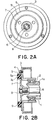
- the power transmission mechanism comprises an outer ring 5, an inner boss 7, and an elastic ring member 9.
- the outer ring 5 is fixed to the pulley 3 by means of three bolts 4 and has an inner circular surface 5a.
- the inner boss 7 is fixed to the shaft 6 by a nut 8 and has an outer circular surface 7a which is opposite to the inner circular surface 5a in a radial direction of the outer ring 5 to form a ring-shaped space therebetween.
- the elastic ring member 9 is placed in the ring-shaped space and circularly extends to form a ring shape. More particularly, the elastic ring member 9 is vulcanization-adhered around the outer circular surface 7a of the inner boss 7 and is press-fitted in the outer ring 5.
- the elastic ring member 9 is made of rubber known in the art.
- an outer diameter of the elastic ring member 9 is set to be slightly greater than an inner diameter of the outer ring 5, that is, a fitting margin is provided, and then the elastic ring member 9 is press-fitted in the outer ring 5.
- the inner boss 7 applied with an adhesive on its outer circumference and the outer ring 5 are set in a rubber vulcanization die, and then melted rubber is injected into the die so that the inner boss 7 is subjected to vulcanization adhesion. In this event, the inner circumference of the outer ring 5 is in contact with the rubber, but does not adhere thereto.
- the outer diameter of the outer ring 5 is reduced. Since a guide diameter D1 of the contraction jig 11 is set greater than an outer diameter D0 of the outer ring 5 after the vulcanization (D1>D0) to provide a proper clearance therebetween, galling between the contraction jig 11 and the outer ring 5 is not caused.
- the contraction jig 11 is provided with a tapered outer circumference 11a and further provided with slits 11b arranged at regular intervals in a circumferential direction thereof to provide split pieces 11c. Accordingly, when a punch 13 is lowered to press the rubber assembly 10 and the contraction jig 11 into a presser jig 12 having a tapered inner circumference 12a, the split pieces 11c are forced inward to press the outer ring 5 so as to have a required diameter D2 (see Fig. 3). This causes the elastic ring member 9 to generate the uniform compressive reaction.
- the contraction jig 11 supported by a spring (not shown) is also raised.
- the contraction jig 11 is made of spring steel or the like, the split pieces 11c are restored to the original diameter D1.
- the contraction margin is given by D0-D2.
- the description will be directed to a relationship between the contract margin or the fitting margin and the transmission shut-off torque.
- the transmission torque becomes about 6 to 7kgfm
- a driving belt of the pulley 3 starts slipping.
- setting the maximum shut-off torque to 6kgfm a contact area between the outer ring 5 and the elastic ring member 9 was set and then a corresponding proper contraction or fitting margin was determined. Since the sufficient safety factor should be ensured relative to the normal load torque of the compressor, the minimum transmission torque was set to 4.5kgfm. Accordingly, the proper contraction or fitting margin was found to be 5 to 10%.
- the torque of the pulley 3 is transmitted to the shaft 6 of the compressor via the outer ring 5, the elastic ring member 9 and the inner boss 7 by means of a frictional force determined by an internal compressive reaction and a friction coefficient of the elastic ring member 9.
- the torque fluctuation during the normal load is relaxed by means of the elastic ring member 9.
- the internal compressive reaction of the elastic ring member 9 is uniform along the entire contact surface of the outer ring 5, and further, the outer ring 5 has no geometrically constrained portions. Thus, the shut-off torque can be held constant.
- Figs 6A and 6B the description will be made as regards a power transmission mechanism according to the second preferred embodiment of the present invention.
- the power transmission mechanism comprises similar parts designated by like reference numerals.
- the pulley 3 has an axial end 3a facing the ring-shaped space that is remained between the outer ring 5 and inner boss 7 in the radial direction.
- the elastic ring member 9 is in press contact with the axial end 3a of the pulley 3.
- the elastic ring member 9 has an axially projected portion 9a confronting the axial end 3a of the pulley 3 and has a part 9b interposed between the pulley 3 and the inner boss 7.
- the power transmission mechanism comprises similar parts designated by like reference numerals.
- the inner circular surface 5a of the outer ring 5 is formed with fine concave and convex portions 13 by shot blasting or knurling processing known in the art, and then are brought in press contact with the elastic ring member 9. Accordingly, the elastic ring member 9 is formed with convex portions and concave portions at an outer peripheral surface thereof. This results in cooperatively providing the fine concave/convex coupling between the outer ring 5 and the elastic ring member 9.
- an outer ring 5 is formed with an inward flange 5b which inwardly extends to face the above-mentioned ring-shaped space and has a plurality of ring-side engaging portions 5c.
- the elastic ring member 9 has a plurality of member-side engaging portions 9c at an axial end thereof.
- the member-side engaging portions 9c are engaged with the ring-side engaging portions 5c when the elastic ring member 9 is press-fitted into the outer ring 5. Through engagement between the engaging portions 5c and 9c, slips can be prevented more reliably. Since each of the engaging portions 5c has a hollow trapezoidal shape in section while each of the engaging portions 9c has a solid trapezoidal shape in section, the transmission shut-off torque is not increased.
- the principal torque transmission is carried out between the inner surface 5a of the outer ring 5 and the outer surface of the elastic ring member 9, while small slips can be prevented between the engaging portions 5c of the outer ring 5 and the engaging portions 9c of the elastic ring member 9.
Landscapes
- Engineering & Computer Science (AREA)
- General Engineering & Computer Science (AREA)
- Mechanical Engineering (AREA)
- Physics & Mathematics (AREA)
- Acoustics & Sound (AREA)
- Aviation & Aerospace Engineering (AREA)
- Transmission Devices (AREA)
- Compressors, Vaccum Pumps And Other Relevant Systems (AREA)
Applications Claiming Priority (3)
| Application Number | Priority Date | Filing Date | Title |
|---|---|---|---|
| JP18641597 | 1997-07-11 | ||
| JP18641597A JPH1130244A (ja) | 1997-07-11 | 1997-07-11 | 動力伝達機構 |
| JP186415/97 | 1997-07-11 |
Publications (3)
| Publication Number | Publication Date |
|---|---|
| EP0890760A2 true EP0890760A2 (de) | 1999-01-13 |
| EP0890760A3 EP0890760A3 (de) | 1999-01-20 |
| EP0890760B1 EP0890760B1 (de) | 2001-01-10 |
Family
ID=16188031
Family Applications (1)
| Application Number | Title | Priority Date | Filing Date |
|---|---|---|---|
| EP19980112655 Expired - Lifetime EP0890760B1 (de) | 1997-07-11 | 1998-07-08 | Leistungsgetriebe mit komprimiertem, elastischem Ringelement zwischen äusserem Ring und innerer Nabe |
Country Status (3)
| Country | Link |
|---|---|
| EP (1) | EP0890760B1 (de) |
| JP (1) | JPH1130244A (de) |
| DE (1) | DE69800479T2 (de) |
Cited By (9)
| Publication number | Priority date | Publication date | Assignee | Title |
|---|---|---|---|---|
| US6612813B2 (en) * | 2000-09-22 | 2003-09-02 | Kabushiki Kaisha Toyota Jidoshokki | Power transmission mechanism |
| US6663521B2 (en) | 2000-08-11 | 2003-12-16 | Kabushiki Kaisha Toyota Jidoshokki | Power transmitting mechanism |
| EP1126195A3 (de) * | 2000-02-18 | 2004-04-21 | Calsonic Kansei Corporation | Leistungsgetriebe |
| EP1462680A1 (de) * | 2003-03-27 | 2004-09-29 | Fujikiko Kabushiki Kaisha | Kraftübertragungseinheit |
| CN103629057A (zh) * | 2013-12-20 | 2014-03-12 | 济南轨道交通装备有限责任公司 | 一种柔性风力发电机组传动系统 |
| CN103670958A (zh) * | 2013-12-20 | 2014-03-26 | 济南轨道交通装备有限责任公司 | 具有减震功能的风力发电机组传动系统 |
| DE10030068B4 (de) * | 1999-06-21 | 2014-12-24 | Denso Corporation | Umlauf-Übertragungsvorrichtung mit Drehmoment-Begrenzungseinrichtung |
| CN105102836A (zh) * | 2013-04-05 | 2015-11-25 | 株式会社电装 | 动力传递装置 |
| CN113280096A (zh) * | 2021-06-28 | 2021-08-20 | 重庆海德世拉索系统(集团)有限公司 | 组合式双联齿轮结构 |
Citations (1)
| Publication number | Priority date | Publication date | Assignee | Title |
|---|---|---|---|---|
| JPH08135752A (ja) | 1994-09-14 | 1996-05-31 | Nippondenso Co Ltd | 動力伝達装置 |
Family Cites Families (4)
| Publication number | Priority date | Publication date | Assignee | Title |
|---|---|---|---|---|
| FR965155A (de) * | 1950-09-05 | |||
| US5377962A (en) * | 1992-08-08 | 1995-01-03 | Firma Carl Freudenberg | Rotational vibration damper |
| US5683299A (en) * | 1994-09-14 | 1997-11-04 | Nippondenso Co., Ltd. | Device for transmitting rotational power |
| JP3476164B2 (ja) * | 1995-04-18 | 2003-12-10 | 株式会社豊田自動織機 | 圧縮機における動力伝達構造 |
-
1997
- 1997-07-11 JP JP18641597A patent/JPH1130244A/ja active Pending
-
1998
- 1998-07-08 EP EP19980112655 patent/EP0890760B1/de not_active Expired - Lifetime
- 1998-07-08 DE DE1998600479 patent/DE69800479T2/de not_active Expired - Fee Related
Patent Citations (1)
| Publication number | Priority date | Publication date | Assignee | Title |
|---|---|---|---|---|
| JPH08135752A (ja) | 1994-09-14 | 1996-05-31 | Nippondenso Co Ltd | 動力伝達装置 |
Cited By (11)
| Publication number | Priority date | Publication date | Assignee | Title |
|---|---|---|---|---|
| DE10030068B4 (de) * | 1999-06-21 | 2014-12-24 | Denso Corporation | Umlauf-Übertragungsvorrichtung mit Drehmoment-Begrenzungseinrichtung |
| EP1126195A3 (de) * | 2000-02-18 | 2004-04-21 | Calsonic Kansei Corporation | Leistungsgetriebe |
| US6663521B2 (en) | 2000-08-11 | 2003-12-16 | Kabushiki Kaisha Toyota Jidoshokki | Power transmitting mechanism |
| US6612813B2 (en) * | 2000-09-22 | 2003-09-02 | Kabushiki Kaisha Toyota Jidoshokki | Power transmission mechanism |
| EP1462680A1 (de) * | 2003-03-27 | 2004-09-29 | Fujikiko Kabushiki Kaisha | Kraftübertragungseinheit |
| CN105102836A (zh) * | 2013-04-05 | 2015-11-25 | 株式会社电装 | 动力传递装置 |
| CN105102836B (zh) * | 2013-04-05 | 2018-04-17 | 株式会社电装 | 动力传递装置 |
| CN103629057A (zh) * | 2013-12-20 | 2014-03-12 | 济南轨道交通装备有限责任公司 | 一种柔性风力发电机组传动系统 |
| CN103670958A (zh) * | 2013-12-20 | 2014-03-26 | 济南轨道交通装备有限责任公司 | 具有减震功能的风力发电机组传动系统 |
| CN103670958B (zh) * | 2013-12-20 | 2015-11-11 | 北车风电有限公司 | 具有减震功能的风力发电机组传动系统 |
| CN113280096A (zh) * | 2021-06-28 | 2021-08-20 | 重庆海德世拉索系统(集团)有限公司 | 组合式双联齿轮结构 |
Also Published As
| Publication number | Publication date |
|---|---|
| JPH1130244A (ja) | 1999-02-02 |
| DE69800479D1 (de) | 2001-02-15 |
| DE69800479T2 (de) | 2001-06-13 |
| EP0890760B1 (de) | 2001-01-10 |
| EP0890760A3 (de) | 1999-01-20 |
Similar Documents
| Publication | Publication Date | Title |
|---|---|---|
| CN101122304B (zh) | 轴及外壳组件的装配 | |
| US5195625A (en) | Torque cushion for electromagnetic clutch | |
| US3788437A (en) | Clutch release bearing | |
| EP0890760B1 (de) | Leistungsgetriebe mit komprimiertem, elastischem Ringelement zwischen äusserem Ring und innerer Nabe | |
| CN100510450C (zh) | 动力传递装置 | |
| US6494799B1 (en) | Power transmission device | |
| US5560464A (en) | Electromagnetic clutch | |
| US5445256A (en) | Electromagnetic clutch | |
| US5944156A (en) | Power transmission mechanism | |
| JP3059368B2 (ja) | 電磁連結装置 | |
| JPH06300055A (ja) | アーマチュア・アセンブリ | |
| JP2007113634A (ja) | プーリ構造体 | |
| US6234904B1 (en) | Drive power transmission apparatus | |
| US6957728B2 (en) | Pulley apparatus with built-in roller clutch and the assembly method thereof | |
| JP5931073B2 (ja) | ステータセンタリングプレート | |
| US20040211063A1 (en) | Method for assembling pulley apparatus with built-in roller clutch | |
| JPH1182582A (ja) | ロックアップダンパー用コイルスプリング組立体 | |
| JPH10132028A (ja) | 動力伝達機構 | |
| JPS6325223B2 (de) | ||
| US20050230208A1 (en) | Power transmission device | |
| US6880689B2 (en) | Pulley apparatus with built-in roller clutch and assembly method thereof | |
| JP2003269489A (ja) | 動力伝達機構 | |
| JPH0972354A (ja) | 電磁連結装置 | |
| JPH08277847A (ja) | 過負荷防止装置 | |
| US5911294A (en) | Clutch cover assembly having a tab members formed on the clutch cover to support a diaphragm spring |
Legal Events
| Date | Code | Title | Description |
|---|---|---|---|
| PUAI | Public reference made under article 153(3) epc to a published international application that has entered the european phase |
Free format text: ORIGINAL CODE: 0009012 |
|
| PUAL | Search report despatched |
Free format text: ORIGINAL CODE: 0009013 |
|
| AK | Designated contracting states |
Kind code of ref document: A2 Designated state(s): DE FR |
|
| AX | Request for extension of the european patent |
Free format text: AL;LT;LV;MK;RO;SI |
|
| AK | Designated contracting states |
Kind code of ref document: A3 Designated state(s): AT BE CH CY DE DK ES FI FR GB GR IE IT LI LU MC NL PT SE |
|
| AX | Request for extension of the european patent |
Free format text: AL;LT;LV;MK;RO;SI |
|
| 17P | Request for examination filed |
Effective date: 19990629 |
|
| 17Q | First examination report despatched |
Effective date: 19990816 |
|
| AKX | Designation fees paid |
Free format text: DE FR |
|
| GRAG | Despatch of communication of intention to grant |
Free format text: ORIGINAL CODE: EPIDOS AGRA |
|
| 17Q | First examination report despatched |
Effective date: 19990816 |
|
| GRAG | Despatch of communication of intention to grant |
Free format text: ORIGINAL CODE: EPIDOS AGRA |
|
| GRAG | Despatch of communication of intention to grant |
Free format text: ORIGINAL CODE: EPIDOS AGRA |
|
| GRAH | Despatch of communication of intention to grant a patent |
Free format text: ORIGINAL CODE: EPIDOS IGRA |
|
| GRAH | Despatch of communication of intention to grant a patent |
Free format text: ORIGINAL CODE: EPIDOS IGRA |
|
| GRAA | (expected) grant |
Free format text: ORIGINAL CODE: 0009210 |
|
| AK | Designated contracting states |
Kind code of ref document: B1 Designated state(s): DE FR |
|
| REF | Corresponds to: |
Ref document number: 69800479 Country of ref document: DE Date of ref document: 20010215 |
|
| ET | Fr: translation filed | ||
| PLBE | No opposition filed within time limit |
Free format text: ORIGINAL CODE: 0009261 |
|
| STAA | Information on the status of an ep patent application or granted ep patent |
Free format text: STATUS: NO OPPOSITION FILED WITHIN TIME LIMIT |
|
| 26N | No opposition filed | ||
| PGFP | Annual fee paid to national office [announced via postgrant information from national office to epo] |
Ref country code: FR Payment date: 20020709 Year of fee payment: 5 |
|
| PGFP | Annual fee paid to national office [announced via postgrant information from national office to epo] |
Ref country code: DE Payment date: 20020717 Year of fee payment: 5 |
|
| PG25 | Lapsed in a contracting state [announced via postgrant information from national office to epo] |
Ref country code: DE Free format text: LAPSE BECAUSE OF NON-PAYMENT OF DUE FEES Effective date: 20040203 |
|
| PG25 | Lapsed in a contracting state [announced via postgrant information from national office to epo] |
Ref country code: FR Free format text: LAPSE BECAUSE OF NON-PAYMENT OF DUE FEES Effective date: 20040331 |
|
| REG | Reference to a national code |
Ref country code: FR Ref legal event code: ST |