EP0890825A1 - Verfahren zum Bestimmen einer planaren Strömung aus einer Doppler-Geschwindigkeitsverteilung in einer Beobachtungsebene - Google Patents
Verfahren zum Bestimmen einer planaren Strömung aus einer Doppler-Geschwindigkeitsverteilung in einer Beobachtungsebene Download PDFInfo
- Publication number
- EP0890825A1 EP0890825A1 EP98112494A EP98112494A EP0890825A1 EP 0890825 A1 EP0890825 A1 EP 0890825A1 EP 98112494 A EP98112494 A EP 98112494A EP 98112494 A EP98112494 A EP 98112494A EP 0890825 A1 EP0890825 A1 EP 0890825A1
- Authority
- EP
- European Patent Office
- Prior art keywords
- flow
- function
- doppler
- planar
- source
- Prior art date
- Legal status (The legal status is an assumption and is not a legal conclusion. Google has not performed a legal analysis and makes no representation as to the accuracy of the status listed.)
- Granted
Links
- 238000000034 method Methods 0.000 title claims abstract description 33
- 230000010354 integration Effects 0.000 claims abstract description 13
- 239000012530 fluid Substances 0.000 claims description 18
- 238000013139 quantization Methods 0.000 claims description 7
- 230000000694 effects Effects 0.000 claims description 6
- 238000004364 calculation method Methods 0.000 claims 1
- 238000010586 diagram Methods 0.000 description 17
- 239000013598 vector Substances 0.000 description 16
- 239000010410 layer Substances 0.000 description 15
- 230000017531 blood circulation Effects 0.000 description 6
- 238000003745 diagnosis Methods 0.000 description 4
- 230000007423 decrease Effects 0.000 description 3
- 230000005540 biological transmission Effects 0.000 description 2
- 238000006073 displacement reaction Methods 0.000 description 2
- 238000009499 grossing Methods 0.000 description 2
- 239000011229 interlayer Substances 0.000 description 2
- 238000005259 measurement Methods 0.000 description 2
- 238000012545 processing Methods 0.000 description 2
- 239000000523 sample Substances 0.000 description 2
- 230000036962 time dependent Effects 0.000 description 2
- 238000013459 approach Methods 0.000 description 1
- 230000001174 ascending effect Effects 0.000 description 1
- 238000007796 conventional method Methods 0.000 description 1
- 238000012937 correction Methods 0.000 description 1
- 239000002674 ointment Substances 0.000 description 1
Images








Classifications
-
- G—PHYSICS
- G01—MEASURING; TESTING
- G01S—RADIO DIRECTION-FINDING; RADIO NAVIGATION; DETERMINING DISTANCE OR VELOCITY BY USE OF RADIO WAVES; LOCATING OR PRESENCE-DETECTING BY USE OF THE REFLECTION OR RERADIATION OF RADIO WAVES; ANALOGOUS ARRANGEMENTS USING OTHER WAVES
- G01S15/00—Systems using the reflection or reradiation of acoustic waves, e.g. sonar systems
- G01S15/88—Sonar systems specially adapted for specific applications
- G01S15/89—Sonar systems specially adapted for specific applications for mapping or imaging
- G01S15/8906—Short-range imaging systems; Acoustic microscope systems using pulse-echo techniques
- G01S15/8979—Combined Doppler and pulse-echo imaging systems
-
- A—HUMAN NECESSITIES
- A61—MEDICAL OR VETERINARY SCIENCE; HYGIENE
- A61B—DIAGNOSIS; SURGERY; IDENTIFICATION
- A61B8/00—Diagnosis using ultrasonic, sonic or infrasonic waves
- A61B8/06—Measuring blood flow
-
- G—PHYSICS
- G01—MEASURING; TESTING
- G01F—MEASURING VOLUME, VOLUME FLOW, MASS FLOW OR LIQUID LEVEL; METERING BY VOLUME
- G01F1/00—Measuring the volume flow or mass flow of fluid or fluent solid material wherein the fluid passes through a meter in a continuous flow
- G01F1/66—Measuring the volume flow or mass flow of fluid or fluent solid material wherein the fluid passes through a meter in a continuous flow by measuring frequency, phase shift or propagation time of electromagnetic or other waves, e.g. using ultrasonic flowmeters
- G01F1/663—Measuring the volume flow or mass flow of fluid or fluent solid material wherein the fluid passes through a meter in a continuous flow by measuring frequency, phase shift or propagation time of electromagnetic or other waves, e.g. using ultrasonic flowmeters by measuring Doppler frequency shift
-
- G—PHYSICS
- G01—MEASURING; TESTING
- G01S—RADIO DIRECTION-FINDING; RADIO NAVIGATION; DETERMINING DISTANCE OR VELOCITY BY USE OF RADIO WAVES; LOCATING OR PRESENCE-DETECTING BY USE OF THE REFLECTION OR RERADIATION OF RADIO WAVES; ANALOGOUS ARRANGEMENTS USING OTHER WAVES
- G01S7/00—Details of systems according to groups G01S13/00, G01S15/00, G01S17/00
- G01S7/52—Details of systems according to groups G01S13/00, G01S15/00, G01S17/00 of systems according to group G01S15/00
- G01S7/52017—Details of systems according to groups G01S13/00, G01S15/00, G01S17/00 of systems according to group G01S15/00 particularly adapted to short-range imaging
- G01S7/52053—Display arrangements
- G01S7/52057—Cathode ray tube displays
- G01S7/52073—Production of cursor lines, markers or indicia by electronic means
Definitions
- This invention relates to a method of estimating planar flow from Doppler velocity distribution in an observation plane of a fluid, and more specifically relates to an improved planar flow estimation method that can display a flow velocity distribution as streamlines while utilizing a flow function by estimating an inflow/outflow flow rate of a boundary line or boundary surface.
- a method to observe the flow velocity distribution of a fluid in an observation plane by using the Doppler effect of an ultrasonic wave is put to practical use, for example, in observing the rate of blood flow in the heart.
- Such a blood flow distribution is displayed in color on an ultrasonic wave tomogram of the heart, and is widely used in diagnosing bloodstream in the heart.
- This Doppler velocity may be found using electromagnetic waves instead of ultrasonic waves. In recent years, it has been widely used to perform flow velocity observations in oceans, lakes or of cloud movements in the air.
- a Doppler velocity distribution can measure only speed components in the transmitted and received wave directions of the observation beam, however it is necessary to estimate also the component in the direction perpendicular to the beam.
- This invention which was conceived in view of the aforesaid current problems, therefore aims to-provide an improved estimation method for estimating planar flow which takes account of inflow/outflow to and from a boundary line or boundary plane from only the observed Doppler velocity distribution.
- this invention comprises a step for scanning an observing beam and scanning a predetermined observation plane in a fluid with this beam, and measuring the Doppler velocity distribution of the fluid from the Doppler frequency of the wave reflected from the observation plane, a step for linearly integrating the Doppler velocity along orthogonal paths which are perpendicular to the beam direction in order to calculate a Doppler flow function at various points on the orthogonal paths, a step for calculating flow rates along these orthogonal paths from the Doppler velocity distribution and calculating a Doppler flow range function representing a variation of this flow rate along the beam direction, a step for separating this Doppler flow range function into a linear boundary flow range function and a planar boundary flow range function based on boundary conditions, a step for quantizing a planar boundary flow function for a predetermined flow rate (referred to as "unit flow rate”) and calculating the quantized planar boundary flow rate which varies in a stepwise manner, a step for estimating sink
- a fluid source or sink appears in a two-dimensional observation plane set in a three-dimensional flow, so the flow in the observation plane cannot be considered to be two-dimensional.
- a stream function is expanded so that the flow can be simulated by a streamline representation even in a two-dimensional observation plane in a three-dimensional space. This streamline represents the flow from source to sink.
- a stream function expanded in this way is called a flow function.
- This frequency variation f d is called the Doppler frequency, and it increases when the distance r is nearer (i.e., when the reflecting object approaches the transmitter/receiver).
- This quantity will be referred to as a (three-dimensional) Doppler flow rate.
- the Doppler velocity u d (x,y,z 0 ) which is then observed has the opposite sign to the velocity component u(x,y,z 0 ) of the observed fluid.
- u d - u
- the stream function can be adapted to this flow rate, and the stream function for two-dimensional flow represents a flow rate based on one point.
- contour line of the stream function is a streamline.
- the contour line of the stream function is a streamline of a two-dimensional flow.
- the linear boundary flow function is a stream function for two-dimensional flow.
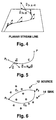
- Fig. 7 is a figure for describing a flow function of a source (streamline starting point). As shown in (a), at the position of the source point, the flow rate varies by the unit flow q. On a clockwise path the flow rate increases, and on an anticlockwise path the flow rate decreases. The flow rate is different even at the same end point for paths containing the point source, and this difference is the unit flow q.
- the flow rate is multi-valued in a plane comprising the source point. Taking the flow rate as height, the flow rate around the source point has a layer structure with a spiral slope which continues infinitely upwards and downwards as shown in (b).
- the flow function of the slope structure it this point source is taken as the simple source flow function Q p (x,y).
- Fig. 8 is a figure for describing a flow function of a sink point source. This case may be treated in a similar manner to that of the source described hereabove. Specifically, (a) the flow rate decreases on a clockwise path around the sink point source, and the flow rate increases on an anticlockwise path around the sink point. Therefore, the flow rate around the sink point has a layer structure with a spiral slope which continues infinitely upwards and downwards as shown in (b). This is also the simple source flow function Q p (x,y).
- a general flow in an observation plane comprising a three-dimensional inflow/outflow may be expressed as a discrete flow function.
- contour lines for unit flow rate coincide for all layers. These contour lines can therefore be grouped together and represented as a streamline in the observation plane.
- the streamlines of the unit flow rate interval can be expressed by contour lines which coincide for all layers of the discrete flow function.
- the discrete flow function will be referred to simply as flow function.
- Flow functions which can represent point sources (simple sources) are generally multi-valued, and this is inconvenient for handling numerical data.
- the value of the flow function is a multi-value which takes a discrete value for unit flow rate, we shall therefore consider expressing the flow function as a combination of a unit flow rate and a single-valued function.
- the single-valued function found in this way will be referred to as a scan flow function. Discontinuities in this scan flow function represent differences of the layers, and continuous flow function values for the same layer may be obtained by adjusting the unit flow rate.
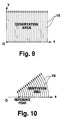
- Fig. 9 shows an example of a path for calculating a linear scan flow function by linear scanning in Cartesian coordinate system
- Fig. 10 shows an example of a path for calculating a sector scan flow function by sector scanning in polar coordinate system.
- the stream function was expanded so that it could be applied also to the case where there is inflow/outflow to and from the observation plane, and this was taken as a flow function.
- the method wherein the flow function is calculated from measured Doppler data and a streamline deduced therefrom is displayed superposed on the Doppler image will be referred to as a flow function method.
- the flow velocity vector component in the observation area can be estimated from the streamline.
- an observation area 20 in the observation plane is an area having straight line boundaries and arc boundaries as shown in Fig. 11.
- the Doppler flow range function Q d (r) shown in Fig. 12 is found from the Doppler velocity distribution in this area.
- the Doppler flow range function Q d (r) shows the flow passing through an arc-shaped path at a distance r from an origin O in the observation area.
- the Doppler flow range function is found by linearly integrating the Doppler velocity at each point on the arc from one end of the arc to the other.
- a simple source flow function can be determined for each of the simple sources found in this way taking account of the spiral slope structure. Also, the superposition of all the simple source flow functions of these simple sources is the simple source flow function Q qs (r, ⁇ ) of the observation area.
- a Doppler scan simple source flow function Q ds (r, ⁇ ) is also found for simple sources by performing the same scan as for the Doppler flow function. Specifically, for a simple source distribution in the observation plane found by the aforesaid method, the Doppler scan simple source flow function Q ds (r, ⁇ ) is found by performing linear integration on the same arc path as when the Doppler flow function is found.
- the one side linear boundary flow function Q b0 (r) represents the flow rate on the side of the boundary line of the observation area which was taken as a reference line to calculate the Doppler flow function Q d (r, ⁇ ).
- the one side linear boundary flow function Q d (r, ⁇ ) which is a function of the distance from the starting point, can be estimated from a real-time tomogram of the observation area obtained by transmission and reception of the observation wave beam.
- a bias C(r) is introduced in order to standardize the reference points of this function to the origin of the observation area.
- the bias C(r) represents a flow rate through a path from the origin to a point at a distance r on the reference line.
- the bias C(r) may be estimated from a realtime tomogram of the observation area obtained by transmission and reception of the observation wave beam. For example, in an ultrasonic wave tomogram of the heart, the bias C(r) may be found based on the displacement of points on the inner wall of the heart between two-frames of tomogram, and the time interval between the two frames.
- this bias C(r) may also be adjusted beforehand so as to eliminate quantization error when the planar boundary flow range function is quantized.
- the streamline of a two-dimensional flow may be expressed by the contour line of the stream function.
- the flow function which can be applied even when there is a three-dimensional inflow/outflow to and from an observation plane with two-dimensional flow is multi-valued. It can be expressed by a single-valued function by specifying the integration path when the function is found.
- the data for the function may be treated as two-dimensional data. A layer structure of the flow function is determined as discontinuities in the data.
- the flow rate difference between layers is the unit flow rate q, so the contour line of the unit flow rate intervals of all layers is displayed as the same planar streamline.
- planar flow may be represented by a (quantized) flow function, and if the contour lines of this (quantized) flow function are drawn with the unit flow rate interval, planar a streamline display is obtained.
- a flow estimated from planar flow information obtained by Doppler weather radar for observing atmospheric flow, or by medical ultrasonic wave color Doppler devices for observing blood flow in the heart, can be displayed as a streamline.
- a linear boundary flow function and a planar boundary flow function are estimated from a Doppler velocity distribution of a wave reflected from an observation plane, and a planar flow can be estimated based thereon by combining the planar flow function and a simple source flow function.
- the estimation method of this invention will be described in further detail.
- Fig. 16 shows an example of Doppler velocity distribution calculated on the basis of the observation wave beam transmitted from a transmitter/receiver when the x-y plane is the observation plane.
- sector scanning was used as an example, but in the following embodiment, a linear scanning observation wave beam is used.
- the observation wave beam from the transmitter/receiver is transmitted in the x direction, and as a result, only the x direction component of the Doppler velocity U is obtained.
- the linear scanning in the figure is performed relative to the y direction, and an observation plane along the scan axis in the y direction is set from y0-y1.
- Fig. 16 only three Doppler velocitys in the x direction, i.e. x1, x2, x3, are shown on the axis in order to simplify the explanation.
- a Doppler flow rate in and Doppler flow function are found in an orthogonal direction to the beam direction, i.e., along the y direction.
- the Doppler flow range function Q d (x) at a distance x is found by integrating the Doppler velocity from y0 to y1 along a perpendicular axis to the beam direction at a position at a distance x from the transmitter/receiver.
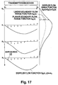
- Fig. 17 shows the Doppler flow rate along the x axis direction
- the Doppler flow range function Q d (x) is shown by a solid line.
- This Q d (x) contains a linear boundary flow range function Q b (x) representing a two-dimensional inflow/outflow to and from a boundary line of the observation area and a planar boundary flow range function Q s (x) representing a three-dimensional inflow/outflow to and from the observation area.
- the Doppler flow range function found as described hereabove is split into a linear boundary flow range function and planar boundary flow range function based on the boundary condition in the observation area.
- Fig. 18 shows a procedure for estimating the distribution of sources/sinks in the observation plane from the planar boundary flow range function Q s (x).
- the aforesaid planar boundary flow range function Q s (x) is first quantized by a unit flow rate q.
- This unit flow rate q is a streamline interval when a planar flow in the observation plane is displayed.
- the step graph on the right side of Fig. 18 shows the state where the planar boundary flow range function is quantized (quantized planar boundary flow range function).
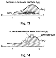
- the positions of the source points or sink points are fixed at locations where the rate of Doppler velocity change in the beam direction is large, as shown by Fig. 13 to Fig. 15 used in describing the principle of the invention.
- Fig. 13 to Fig. 15 used in describing the principle of the invention.
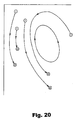
- planar flow function based on Fig. 18 and the simple source flow function due to the simple source distribution shown in Fig. 19, the planar flow can be estimated by combining the two.
- Fig. 20 shows an example of a planar flow resulting from this combination.
- the distribution of Doppler velocity u d (r, ⁇ ) in the observation area based on the Doppler method is found by transmitting an observation wave beam (S1).
- the Doppler flow range function Q d (r) is then found as a function of the distance r by integrating the Doppler velocity u d along the arc perpendicular to the beam direction from the side boundary which is the reference line of the observation area to the other side boundary (S3).
- the linear boundary flow range function Q b (r) which shows the two-dimensional flow in the observation area is found from the boundary conditions, and the planar boundary flow range function Q s (r) which represents three-dimensional inflow/outflow relative to the observation area is found by subtracting Q b (r) from the Doppler flow range function Q d (r) (S4).
- the quantized planar boundary flow range function Q qs (r) is then found by approximating this planar boundary flow range function Q s (r) by a step function which varies with unit flow rate q (S5). Based on this quantized planar boundary flow range function Q qs (r), a sink position and a source position representing three-dimensional inflow/outflow relative to the observation area are found (S6).
- S2-S12 may be performed by having a digital computer execute a program comprising the contents of each step.
- planar flow is shown as a flow function as mentioned hereabove, and by superposing it on a two-dimensional Doppler image, it provides a display with a very high level of recognition.
Landscapes
- Physics & Mathematics (AREA)
- Engineering & Computer Science (AREA)
- Health & Medical Sciences (AREA)
- Life Sciences & Earth Sciences (AREA)
- Radar, Positioning & Navigation (AREA)
- Remote Sensing (AREA)
- Acoustics & Sound (AREA)
- General Physics & Mathematics (AREA)
- Biomedical Technology (AREA)
- Animal Behavior & Ethology (AREA)
- Biophysics (AREA)
- Nuclear Medicine, Radiotherapy & Molecular Imaging (AREA)
- Pathology (AREA)
- Radiology & Medical Imaging (AREA)
- Computer Networks & Wireless Communication (AREA)
- Heart & Thoracic Surgery (AREA)
- Medical Informatics (AREA)
- Molecular Biology (AREA)
- Surgery (AREA)
- Hematology (AREA)
- General Health & Medical Sciences (AREA)
- Public Health (AREA)
- Veterinary Medicine (AREA)
- Electromagnetism (AREA)
- Fluid Mechanics (AREA)
- Ultra Sonic Daignosis Equipment (AREA)
- Measuring Volume Flow (AREA)
- Indicating Or Recording The Presence, Absence, Or Direction Of Movement (AREA)
- Radar Systems Or Details Thereof (AREA)
Applications Claiming Priority (6)
| Application Number | Priority Date | Filing Date | Title |
|---|---|---|---|
| JP18151597 | 1997-07-07 | ||
| JP181515/97 | 1997-07-07 | ||
| JP18151597 | 1997-07-07 | ||
| JP18208998 | 1998-06-29 | ||
| JP18208998A JP4126114B2 (ja) | 1997-07-07 | 1998-06-29 | 流体の観測面内ドプラ速度分布から面内流を推定する方法 |
| JP182089/98 | 1998-06-29 |
Publications (2)
| Publication Number | Publication Date |
|---|---|
| EP0890825A1 true EP0890825A1 (de) | 1999-01-13 |
| EP0890825B1 EP0890825B1 (de) | 2004-03-03 |
Family
ID=26500668
Family Applications (1)
| Application Number | Title | Priority Date | Filing Date |
|---|---|---|---|
| EP98112494A Expired - Lifetime EP0890825B1 (de) | 1997-07-07 | 1998-07-06 | Verfahren zum Bestimmen einer planaren Strömung aus einer Doppler-Geschwindigkeitsverteilung in einer Beobachtungsebene |
Country Status (7)
| Country | Link |
|---|---|
| US (1) | US5947903A (de) |
| EP (1) | EP0890825B1 (de) |
| JP (1) | JP4126114B2 (de) |
| AT (1) | ATE261110T1 (de) |
| DE (1) | DE69822043T2 (de) |
| DK (1) | DK0890825T3 (de) |
| ES (1) | ES2216213T3 (de) |
Cited By (2)
| Publication number | Priority date | Publication date | Assignee | Title |
|---|---|---|---|---|
| EP0919832A3 (de) * | 1997-09-30 | 1999-11-17 | Shigeo Ohtsuki | Verfahren zur Anzeige von Planarströmung |
| US11506783B2 (en) | 2018-03-09 | 2022-11-22 | Purdue Research Foundation | Method of processing an image |
Families Citing this family (24)
| Publication number | Priority date | Publication date | Assignee | Title |
|---|---|---|---|---|
| US6871148B2 (en) * | 2002-07-02 | 2005-03-22 | Battelle Memorial Institute | Ultrasonic system and technique for fluid characterization |
| US7152490B1 (en) | 2005-08-15 | 2006-12-26 | Daniel Measurement And Control, Inc. | Methods for determining transducer delay time and transducer separation in ultrasonic flow meters |
| JP4698686B2 (ja) * | 2008-01-04 | 2011-06-08 | アロカ株式会社 | 流れの観測装置 |
| DE102008053073B4 (de) * | 2008-10-24 | 2010-08-05 | Tomtec Imaging Systems Gmbh | Dreidimensionale Ableitung einer proximalen isokinetischen Schale einer proximalen Flusskonvergenzzonze sowie dreidimensionale PISA-Flussmessung |
| CN101919712B (zh) * | 2010-08-25 | 2012-07-25 | 四川省医学科学院(四川省人民医院) | 基于多普勒图像信息的心脏流场平面流线可视化描述方法 |
| EP2514368B1 (de) | 2011-04-18 | 2017-09-20 | TomTec Imaging Systems GmbH | Verfahren zur Transformation eines Doppler-Geschwindigkeitsdatensatzes in ein Geschwindigkeitsvektorfeld |
| KR101348771B1 (ko) * | 2011-12-28 | 2014-01-07 | 삼성메디슨 주식회사 | 벡터 도플러를 이용하여 파티클의 움직임을 추정하는 초음파 시스템 및 방법 |
| KR101348773B1 (ko) * | 2011-12-29 | 2014-01-09 | 삼성메디슨 주식회사 | 벡터 도플러를 이용하여 난류 정보를 제공하는 초음파 시스템 및 방법 |
| KR102185727B1 (ko) * | 2014-01-28 | 2020-12-02 | 삼성메디슨 주식회사 | 초음파 진단 장치 및 그 동작방법 |
| JP5844430B1 (ja) * | 2014-06-27 | 2016-01-20 | 日立アロカメディカル株式会社 | 超音波診断装置 |
| US10929910B2 (en) | 2016-04-21 | 2021-02-23 | Saba Mario Markeci | Method and apparatus for providing a marketplace for distributors and businesses |
| KR102443626B1 (ko) | 2016-11-29 | 2022-09-14 | 블랙모어 센서스 앤드 애널리틱스, 엘엘씨 | 포인트 클라우드 데이터 세트에서 객체의 분류를 위한 방법 및 시스템 |
| CN110140064B (zh) | 2016-11-30 | 2023-07-18 | 布莱克莫尔传感器和分析有限责任公司 | 利用光学测距系统进行自动实时自适应扫描的方法和系统 |
| CN110114632B (zh) | 2016-11-30 | 2021-10-29 | 布莱克莫尔传感器和分析有限责任公司 | 用于对光学啁啾距离检测进行多普勒检测和多普勒校正的方法和系统 |
| WO2018125438A2 (en) | 2016-11-30 | 2018-07-05 | Blackmore Sensors and Analytics Inc. | Method and system for adaptive scanning with optical ranging systems |
| US10422880B2 (en) | 2017-02-03 | 2019-09-24 | Blackmore Sensors and Analytics Inc. | Method and system for doppler detection and doppler correction of optical phase-encoded range detection |
| US10401495B2 (en) | 2017-07-10 | 2019-09-03 | Blackmore Sensors and Analytics Inc. | Method and system for time separated quadrature detection of doppler effects in optical range measurements |
| US10966686B2 (en) | 2017-07-14 | 2021-04-06 | Samsung Medison Co., Ltd. | Ultrasound diagnosis apparatus and method of operating the same |
| ES2951074T3 (es) | 2017-09-23 | 2023-10-17 | Amid S R L | Método y dispositivo para sincronización eléctrica cardíaca |
| WO2019209727A1 (en) * | 2018-04-23 | 2019-10-31 | Blackmore Sensors and Analytics Inc. | Method and system for controlling autonomous vehicle using coherent range doppler optical sensors |
| US11822010B2 (en) | 2019-01-04 | 2023-11-21 | Blackmore Sensors & Analytics, Llc | LIDAR system |
| CN113260873A (zh) | 2019-01-04 | 2021-08-13 | 布莱克莫尔传感器和分析有限责任公司 | 带有具有折射分面的可旋转多边形偏转器的lidar设备 |
| US12130363B2 (en) | 2022-02-03 | 2024-10-29 | Aurora Operations, Inc. | LIDAR system |
| US12571914B2 (en) | 2023-10-05 | 2026-03-10 | Aurora Operations, Inc. | Systems and methods of LIDAR sensor systems having amplifier protection circuits |
Citations (1)
| Publication number | Priority date | Publication date | Assignee | Title |
|---|---|---|---|---|
| EP0379593A1 (de) * | 1988-06-30 | 1990-08-01 | Shigeo Ohtsuki | Doppler-gerät zur messung der verteilung der strömungsgeschwindigkeit |
Family Cites Families (5)
| Publication number | Priority date | Publication date | Assignee | Title |
|---|---|---|---|---|
| US3906791A (en) * | 1973-10-01 | 1975-09-23 | Panametrics | Area averaging ultrasonic flowmeters |
| US5201313A (en) * | 1989-09-04 | 1993-04-13 | Hitachi, Ltd. | Ultrasonic flowmeter |
| US5425365A (en) * | 1992-03-26 | 1995-06-20 | Kabushiki Kaisha Toshiba | Ultrasonic diagnosis apparatus utilizing Doppler technique |
| US5390548A (en) * | 1993-03-18 | 1995-02-21 | The United States Of America As Represented By The Secretary Of The Navy | Electrode array electromagnetic velocimeter |
| GB9309861D0 (en) * | 1993-05-13 | 1993-06-23 | Univ Hospital London Dev Corp | Ultrasonic blood volume flow rate meter |
-
1998
- 1998-06-29 JP JP18208998A patent/JP4126114B2/ja not_active Expired - Fee Related
- 1998-07-06 AT AT98112494T patent/ATE261110T1/de active
- 1998-07-06 EP EP98112494A patent/EP0890825B1/de not_active Expired - Lifetime
- 1998-07-06 DE DE69822043T patent/DE69822043T2/de not_active Expired - Lifetime
- 1998-07-06 DK DK98112494T patent/DK0890825T3/da active
- 1998-07-06 ES ES98112494T patent/ES2216213T3/es not_active Expired - Lifetime
- 1998-07-06 US US09/110,146 patent/US5947903A/en not_active Expired - Lifetime
Patent Citations (1)
| Publication number | Priority date | Publication date | Assignee | Title |
|---|---|---|---|---|
| EP0379593A1 (de) * | 1988-06-30 | 1990-08-01 | Shigeo Ohtsuki | Doppler-gerät zur messung der verteilung der strömungsgeschwindigkeit |
Cited By (3)
| Publication number | Priority date | Publication date | Assignee | Title |
|---|---|---|---|---|
| EP0919832A3 (de) * | 1997-09-30 | 1999-11-17 | Shigeo Ohtsuki | Verfahren zur Anzeige von Planarströmung |
| US6211888B1 (en) | 1997-09-30 | 2001-04-03 | Kotaro Fukuda | Planar flow display method |
| US11506783B2 (en) | 2018-03-09 | 2022-11-22 | Purdue Research Foundation | Method of processing an image |
Also Published As
| Publication number | Publication date |
|---|---|
| US5947903A (en) | 1999-09-07 |
| ATE261110T1 (de) | 2004-03-15 |
| EP0890825B1 (de) | 2004-03-03 |
| JPH1183564A (ja) | 1999-03-26 |
| ES2216213T3 (es) | 2004-10-16 |
| JP4126114B2 (ja) | 2008-07-30 |
| DK0890825T3 (da) | 2004-07-05 |
| DE69822043D1 (de) | 2004-04-08 |
| DE69822043T2 (de) | 2005-01-27 |
Similar Documents
| Publication | Publication Date | Title |
|---|---|---|
| EP0890825B1 (de) | Verfahren zum Bestimmen einer planaren Strömung aus einer Doppler-Geschwindigkeitsverteilung in einer Beobachtungsebene | |
| JP4269623B2 (ja) | 血流可視化診断装置 | |
| US9113826B2 (en) | Ultrasonic diagnosis apparatus, image processing apparatus, control method for ultrasonic diagnosis apparatus, and image processing method | |
| US5031154A (en) | Three-dimensional object imaging method and system | |
| Huang et al. | Time domain Doppler estimators of the amplitude of vibrating targets | |
| CN106442631B (zh) | 基于电学/超声双模态融合的层状界面重建方法 | |
| Asami et al. | Ultrasonic vascular vector flow mapping for 2-D flow estimation | |
| EP0919832B1 (de) | Verfahren zur Anzeige von Planarströmung | |
| US6606089B1 (en) | Method for visualizing a spatially resolved data set | |
| Bucker | A simple 3‐D Gaussian beam sound propagation model for shallow water | |
| Devaney | Generalized projection-slice theorem for fan beam diffraction tomography | |
| Barriere et al. | Diffraction effects in the parametric interaction of acoustic waves: application to measurements of the nonlinearity parameter B/A in liquids | |
| SE468184B (sv) | Syntetisk aperturradar | |
| Fawcett et al. | Evaluation of the integrals of target/seabed scattering using the method of complex images | |
| Geiman et al. | A comparison of algorithms for tracking sub-pixel speckle motion | |
| Ladas et al. | Application of an ART algorithm in an experimental study of ultrasonic diffraction tomography | |
| Shen et al. | Surface‐to‐subsurface velocity projection for shallow water currents | |
| White | Modelling of sound propagation in the ocean | |
| JP3112158B2 (ja) | 音源レベル測定方法および音源レベル測定装置 | |
| Morsy et al. | 3D ultrasound tissue motion tracking using correlation search | |
| Greenleaf | A graphical description of scattering | |
| Ashrafzadeh et al. | Analysis of velocity estimation error for a multidimensional Doppler ultrasound system | |
| Devaney | Inverse Scattering Theory Foundations Of Tomography With Diffracting Wavefields. | |
| Morsy et al. | Detection and quantification of true 3D motion components of the myocardium using 3D speckle tracking in volumetric ultrasound scans: simulations and initial experimental results | |
| Snezhko et al. | External force generation for object segmentation on 3D ultrasound images using simplex meshes |
Legal Events
| Date | Code | Title | Description |
|---|---|---|---|
| PUAI | Public reference made under article 153(3) epc to a published international application that has entered the european phase |
Free format text: ORIGINAL CODE: 0009012 |
|
| AK | Designated contracting states |
Kind code of ref document: A1 Designated state(s): AT CH DE DK ES FR GB IT LI NL SE |
|
| AX | Request for extension of the european patent |
Free format text: AL;LT;LV;MK;RO;SI |
|
| 17P | Request for examination filed |
Effective date: 19990617 |
|
| AKX | Designation fees paid |
Free format text: AT CH DE DK ES FR GB IT LI NL SE |
|
| GRAP | Despatch of communication of intention to grant a patent |
Free format text: ORIGINAL CODE: EPIDOSNIGR1 |
|
| GRAS | Grant fee paid |
Free format text: ORIGINAL CODE: EPIDOSNIGR3 |
|
| GRAA | (expected) grant |
Free format text: ORIGINAL CODE: 0009210 |
|
| AK | Designated contracting states |
Kind code of ref document: B1 Designated state(s): AT CH DE DK ES FR GB IT LI NL SE |
|
| REG | Reference to a national code |
Ref country code: GB Ref legal event code: FG4D |
|
| REG | Reference to a national code |
Ref country code: CH Ref legal event code: EP |
|
| REF | Corresponds to: |
Ref document number: 69822043 Country of ref document: DE Date of ref document: 20040408 Kind code of ref document: P |
|
| REG | Reference to a national code |
Ref country code: CH Ref legal event code: NV Representative=s name: TROESCH SCHEIDEGGER WERNER AG |
|
| REG | Reference to a national code |
Ref country code: SE Ref legal event code: TRGR |
|
| REG | Reference to a national code |
Ref country code: DK Ref legal event code: T3 |
|
| REG | Reference to a national code |
Ref country code: ES Ref legal event code: FG2A Ref document number: 2216213 Country of ref document: ES Kind code of ref document: T3 |
|
| ET | Fr: translation filed | ||
| PLBE | No opposition filed within time limit |
Free format text: ORIGINAL CODE: 0009261 |
|
| STAA | Information on the status of an ep patent application or granted ep patent |
Free format text: STATUS: NO OPPOSITION FILED WITHIN TIME LIMIT |
|
| 26N | No opposition filed |
Effective date: 20041206 |
|
| REG | Reference to a national code |
Ref country code: FR Ref legal event code: PLFP Year of fee payment: 19 |
|
| REG | Reference to a national code |
Ref country code: FR Ref legal event code: PLFP Year of fee payment: 20 |
|
| PGFP | Annual fee paid to national office [announced via postgrant information from national office to epo] |
Ref country code: NL Payment date: 20170720 Year of fee payment: 20 |
|
| PGFP | Annual fee paid to national office [announced via postgrant information from national office to epo] |
Ref country code: GB Payment date: 20170724 Year of fee payment: 20 Ref country code: FR Payment date: 20170720 Year of fee payment: 20 Ref country code: ES Payment date: 20170818 Year of fee payment: 20 Ref country code: DE Payment date: 20170726 Year of fee payment: 20 Ref country code: CH Payment date: 20170724 Year of fee payment: 20 Ref country code: IT Payment date: 20170721 Year of fee payment: 20 |
|
| PGFP | Annual fee paid to national office [announced via postgrant information from national office to epo] |
Ref country code: DK Payment date: 20170724 Year of fee payment: 20 Ref country code: SE Payment date: 20170724 Year of fee payment: 20 Ref country code: AT Payment date: 20170719 Year of fee payment: 20 |
|
| REG | Reference to a national code |
Ref country code: DE Ref legal event code: R071 Ref document number: 69822043 Country of ref document: DE |
|
| REG | Reference to a national code |
Ref country code: DK Ref legal event code: EUP Effective date: 20180706 |
|
| REG | Reference to a national code |
Ref country code: NL Ref legal event code: MK Effective date: 20180705 |
|
| REG | Reference to a national code |
Ref country code: GB Ref legal event code: PE20 Expiry date: 20180705 |
|
| REG | Reference to a national code |
Ref country code: CH Ref legal event code: PL |
|
| REG | Reference to a national code |
Ref country code: AT Ref legal event code: MK07 Ref document number: 261110 Country of ref document: AT Kind code of ref document: T Effective date: 20180706 |
|
| REG | Reference to a national code |
Ref country code: SE Ref legal event code: EUG |
|
| PG25 | Lapsed in a contracting state [announced via postgrant information from national office to epo] |
Ref country code: GB Free format text: LAPSE BECAUSE OF EXPIRATION OF PROTECTION Effective date: 20180705 |
|
| REG | Reference to a national code |
Ref country code: ES Ref legal event code: FD2A Effective date: 20200723 |
|
| PG25 | Lapsed in a contracting state [announced via postgrant information from national office to epo] |
Ref country code: ES Free format text: LAPSE BECAUSE OF EXPIRATION OF PROTECTION Effective date: 20180707 |