EP0890833A2 - Method for determining the calorific state of steam, in particular for determining the wetness of steam and apparatus therefore - Google Patents
Method for determining the calorific state of steam, in particular for determining the wetness of steam and apparatus therefore Download PDFInfo
- Publication number
- EP0890833A2 EP0890833A2 EP98111038A EP98111038A EP0890833A2 EP 0890833 A2 EP0890833 A2 EP 0890833A2 EP 98111038 A EP98111038 A EP 98111038A EP 98111038 A EP98111038 A EP 98111038A EP 0890833 A2 EP0890833 A2 EP 0890833A2
- Authority
- EP
- European Patent Office
- Prior art keywords
- cooling
- steam
- cooling fluid
- condensate
- mass flow
- Prior art date
- Legal status (The legal status is an assumption and is not a legal conclusion. Google has not performed a legal analysis and makes no representation as to the accuracy of the status listed.)
- Withdrawn
Links
- 238000000034 method Methods 0.000 title claims abstract description 36
- 238000001816 cooling Methods 0.000 claims abstract description 153
- 238000010438 heat treatment Methods 0.000 claims abstract description 37
- 239000012809 cooling fluid Substances 0.000 claims description 150
- 238000001514 detection method Methods 0.000 claims description 40
- 239000012530 fluid Substances 0.000 claims description 29
- 238000002156 mixing Methods 0.000 claims description 20
- 239000007789 gas Substances 0.000 claims description 12
- 239000000203 mixture Substances 0.000 claims description 9
- 238000009413 insulation Methods 0.000 claims description 6
- 238000012546 transfer Methods 0.000 claims description 3
- 238000007599 discharging Methods 0.000 claims 1
- 239000000498 cooling water Substances 0.000 description 10
- 238000005259 measurement Methods 0.000 description 8
- 239000000523 sample Substances 0.000 description 8
- 229920006395 saturated elastomer Polymers 0.000 description 7
- XLYOFNOQVPJJNP-UHFFFAOYSA-N water Substances O XLYOFNOQVPJJNP-UHFFFAOYSA-N 0.000 description 6
- 238000004364 calculation method Methods 0.000 description 5
- 238000010586 diagram Methods 0.000 description 5
- 238000004458 analytical method Methods 0.000 description 4
- 230000033228 biological regulation Effects 0.000 description 4
- 230000001105 regulatory effect Effects 0.000 description 4
- 230000001954 sterilising effect Effects 0.000 description 4
- 238000004659 sterilization and disinfection Methods 0.000 description 4
- 238000011217 control strategy Methods 0.000 description 3
- 230000001276 controlling effect Effects 0.000 description 3
- 239000002826 coolant Substances 0.000 description 3
- 230000002349 favourable effect Effects 0.000 description 3
- 230000001376 precipitating effect Effects 0.000 description 3
- 230000015572 biosynthetic process Effects 0.000 description 2
- 238000009835 boiling Methods 0.000 description 2
- 238000004422 calculation algorithm Methods 0.000 description 2
- 238000009833 condensation Methods 0.000 description 2
- 230000005494 condensation Effects 0.000 description 2
- 238000012937 correction Methods 0.000 description 2
- 239000007788 liquid Substances 0.000 description 2
- 239000000463 material Substances 0.000 description 2
- 238000012544 monitoring process Methods 0.000 description 2
- 238000013022 venting Methods 0.000 description 2
- LFQSCWFLJHTTHZ-UHFFFAOYSA-N Ethanol Chemical compound CCO LFQSCWFLJHTTHZ-UHFFFAOYSA-N 0.000 description 1
- 239000002253 acid Substances 0.000 description 1
- 239000000654 additive Substances 0.000 description 1
- 230000000996 additive effect Effects 0.000 description 1
- 239000003570 air Substances 0.000 description 1
- 239000012080 ambient air Substances 0.000 description 1
- 230000009286 beneficial effect Effects 0.000 description 1
- 229910010293 ceramic material Inorganic materials 0.000 description 1
- 238000001311 chemical methods and process Methods 0.000 description 1
- 238000010276 construction Methods 0.000 description 1
- 239000000110 cooling liquid Substances 0.000 description 1
- 238000009795 derivation Methods 0.000 description 1
- 238000013461 design Methods 0.000 description 1
- 230000000694 effects Effects 0.000 description 1
- 230000017525 heat dissipation Effects 0.000 description 1
- 230000002706 hydrostatic effect Effects 0.000 description 1
- 239000011810 insulating material Substances 0.000 description 1
- 238000013208 measuring procedure Methods 0.000 description 1
- 238000005086 pumping Methods 0.000 description 1
- 238000007789 sealing Methods 0.000 description 1
- 125000006850 spacer group Chemical group 0.000 description 1
- 238000011144 upstream manufacturing Methods 0.000 description 1
- 238000004804 winding Methods 0.000 description 1
Images


Classifications
-
- G—PHYSICS
- G01—MEASURING; TESTING
- G01N—INVESTIGATING OR ANALYSING MATERIALS BY DETERMINING THEIR CHEMICAL OR PHYSICAL PROPERTIES
- G01N25/00—Investigating or analyzing materials by the use of thermal means
- G01N25/56—Investigating or analyzing materials by the use of thermal means by investigating moisture content
- G01N25/58—Investigating or analyzing materials by the use of thermal means by investigating moisture content by measuring changes of properties of the material due to heat, cold or expansion
- G01N25/60—Investigating or analyzing materials by the use of thermal means by investigating moisture content by measuring changes of properties of the material due to heat, cold or expansion for determining the wetness of steam
Definitions
- the invention relates to a method and a device for detecting the caloric Condition of steam, in particular for determining the steam wetness of Wet steam.
- wet steam is referred to as a steam medium that only partially consists of saturated steam.
- the proportion of the mass of saturated steam in the total mass of steam is referred to as steam content "X”.
- the value "1-X” is referred to below as the wetness of wet steam.
- the recording of the caloric state of steam is in technical applications, for example the use of steam as a working medium in machines the use of steam in chemical processes, and in particular in the Use of steam as a heating medium is important.
- the caloric state is this steam medium by specifying the steam content (X) in addition to pressure and temperature clearly determined.
- the caloric state of wet steam can be expected at high values of X in a simple way that the steam by adiabatic throttling is relaxed to a superheated steam state.
- By measuring pressure and Temperature of this superheated steam as well as taking into account the Adiabatic throttling through the pressure gradient can be based on the caloric state of the pre-adiabatic throttling Wet steam can be closed.
- the measuring accuracy of the known methods can be increased by increasing the Steam analysis branched partial steam quantities can be increased.
- the object of the invention is based on specifying a method which enables a precise determination of the on a Examination location of the actual vapor state, especially in the With regard to the dampness of the steam.
- the instantaneous value of the steam wetness is advantageously based on the Instantaneous value of the condensate mass flow and the instantaneous value of the Cooling device inflowing heat output in connection with that via a pressure detection device detected pressure of the steam present.
- a pressure detection device detected pressure of the steam present alternative to the detection of the pressure of the steam, it is also possible to adjust the temperature of the Detect steam and based on the detected temperature in connection with the instantaneous condensate mass flow and the instantaneous heating power the instantaneous value to determine the steam wetness. It is also possible to change both the temperature as well as the pressure of the steam, taking into account the combined consideration a particularly precise determination of the instantaneous value of these two variables the steam state, especially the steam wetness is possible.
- the wet steam flowing to the cooling device is continuously condensed and the energy supplied here is permanently dissipated by the cooling device.
- the cooling device is advantageously continuously cooled by a cooling fluid flows through, the outlet temperature of the cooling fluid after passage of the Cooling device is detected.
- the inlet temperature is also advantageous of the cooling fluid detected before entering the cooling device.
- On the detection of the inlet temperature of the cooling fluid before entering the cooling device can then be dispensed with if it is otherwise ensured that the inlet temperature of the cooling fluid is kept at a predetermined value.
- Based on the known Input temperature of the cooling fluid and the detected output temperature of the cooling fluid can measure the cooling device by measuring the cooling fluid mass flow detected by the wet steam supplied heating power or the instantaneous heat flow become.
- wet steam On the basis of the detected heating power in connection with the current condensate mass flow the specific enthalpy of the flowing to the cooling device Wet steam can be determined. Based on the determined specific enthalpy of the incoming wet steam and the current pressure or temperature value the instantaneous wetness of the wet steam can be calculated. The Calculation of the steam wetness from the current specific enthalpy and the The currently measured pressure or temperature value can be determined using an approximation function or using a map, which or the essence the correlations set out in the Mollier h-s diagram wearing.
- Embodiment of the method is given in that the cooling device supplied steam comes into contact with the cooling fluid. This makes it special rapid heat transfer and rapid condensation of the wet steam possible.
- a separate derivation of the in the cooling device can be advantageous formed condensates are dispensed with. It also becomes possible to have a separate Dispensing with the discharge temperature of the condensate.
- Cooling fluid supplied is advantageously inside the cooling device a cooling section is formed, within which the incoming wet steam cools down, the cooling steam permanently by the pressure of the steam system is driven to the cooling section, fully condensed and the resulting Condensate mixes in the cooling fluid.
- the mixing range is the temperature of the fluid mixture of cooling fluid and condensate detected. This advantageously makes it possible to reduce the impact Heat losses after the cooling device towards the determination of the steam wetness reduce.
- cooling fluid through a Cooling circuit circulates, the cooling device and a heat exchange device comprises, wherein the heat exchange device, the cooling fluid to said inlet temperature cools down.
- This cooling circuit is apart from that in the cooling device If applicable, the intended mixing area, a cooling circuit that is closed per se, in which a predetermined cooling fluid volume is added.
- the cooling circuit in advantageously branched fluid permanently.
- the mass flow of the permanent Fluid diverted from the cooling circuit essentially corresponds to the same Time in the cooling fluid mixed in condensate mass flow.
- This Condensate mass flow is advantageously kept essentially constant. This is achieved in an advantageous manner in that the cooling circuit branched fluid flow is kept constant. It will be advantageous possible, indirectly the mass flow of the cooling device To control steam because there is insufficient removal of fluid from the cooling circuit the mixing area formed in the cooling device "overflows", as a result of which the Cooling of the incoming steam reduces the effective cooling surface and inevitably less condensate is formed.
- the amount drawn from the cooling circuit Fluids do not have to be kept constantly constant, but can in particular by a computing device in accordance with a predetermined control strategy be regulated.
- the fluid withdrawn from the cooling circuit or the fluid that forms in the cooling device Condensate is advantageously based on its content of non-condensable Gases analyzed. This makes it particularly useful for volumetric measurements of the condensate mass flow possible, possibly caused by gas inclusions Switch off measurement errors when determining the mass flow.
- a venting device is advantageously provided, through which any non-condensable gases can be branched off. This venting device is advantageously sequential in the cooling fluid flow direction of the cooling device arranged.
- the analysis of the branched-off fluid or the condensate formed with regard to any portions of non-condensable gases contained therein are advantageously carried out Way using a capillary tube.
- this capillary tube the with the non-condensable gases, gas bubble sections carried with the wet steam, the length of these gas bubble sections being directly proportional to the volume of the respective one Is gas bubble sections.
- the outside of the supply of wet steam heat the intended pipe exactly to the temperature of the wet steam, so that there is no temperature difference between the inside and outside of the line is present and there is no heat exchange between the medium inside the Line device and the medium surrounding the line device takes place.
- the diameter of the line device is preferably less than 3 mm.
- the line device is advantageously made of a plastic material manufactured.
- the steam branched off via the line device flows due to an intermediate the branching point and the cooling device existing extremely low pressure drop to the cooling device.
- the line cross section of the line device is dimensioned such that the branched Steam enters the cooling device essentially unthrottled.
- the total length of the line device is kept as short as possible.
- the pressure of the cooling fluid in the cooling device is in one embodiment of the Method in which a mixture of the cooling fluid and the wet steam condensate takes place, substantially equal to the pressure of the line device incoming wet steam.
- the instantaneous value of the steam wetness is advantageously determined in connection with a programmed computer device, the computer device the instantaneous value of the steam wetness based on the instantaneous condensate mass flow, the current heating output and the current temperature and / or the instantaneous pressure of the wet steam is calculated.
- the one for calculation the current steam wetness processed by the computer device Computational algorithm includes, in addition to those required to determine the moisture content of the steam Arithmetic operations according to the Mollier h-s diagram advantageously additional correction terms that reflect the thermal capacity of the measuring system and take into account the pressure and temperature dependency of the dissipation losses.
- the heating power of the Cooling device incoming steam can be detected with high accuracy.
- any lost heat flow emitted by the cooling device can be replaced by a corresponding one Correction term, for example the output temperature of the cooling device and the ambient temperature is taken into account, largely compensated for become.
- the values h d ′′ and h d ′ required for determining the vapor content X are each clearly assigned to certain pressure or temperature values and can be taken, for example, iteratively from approximate equations or corresponding, preferably stored, characteristic maps.
- a device for determining the vapor wetness of wet steam the above-mentioned object achieved according to the invention by a device a wet steam supply device, a cooling device for condensing one by the amount of wet steam supplied by the wet steam supply device, a condensate drainage device to drain the condensate from the cooling device, one Condensate quantity detection device for detecting the mass flow of the forming condensate, a heating power detection device for detection the heating power of the wet steam supplied to the cooling device and a computer device for the calculation of the instantaneous value of the steam wetness in accordance with of the condensate mass flow and the heating power of the in the cooling device precipitating wet steam.
- the device according to the invention can be produced in a compact manner and enables one continuous analysis of the caloric state of steam, the caloric Condition of the steam with the branching off of comparatively small amounts of partial steam can be determined.
- the cooling device is advantageously surrounded by a thermal insulation device, to suppress heat transfer between the cooling device and the environment. This advantageously ensures that the cooling device supplied heating power by measuring the heating of the cooling water can be recorded precisely.
- the heating power detection device advantageously comprises a first temperature measuring point to record the cooling fluid inlet temperature and a second Temperature measuring point for recording a cooling fluid outlet temperature. Based on Heating of the cooling fluid can be in connection with the mass flow of the cooling fluid the heating power supplied to the cooling device can be precisely detected.
- a particularly precise detection of the heating power is thereby advantageously possible that the second temperature measuring point within the cooling device surrounding thermal insulation device is arranged. This will make it beneficial Possible way, the influence of any heat loss in the pipe system almost completely suppressed up to the second temperature measuring point mentioned.
- the cooling device is integrated into a cooling fluid circuit arrangement, the cooling fluid circulated through the cooling fluid circuit assembly. This makes it possible to use the device independent of a separate cooling fluid - especially cold water source operate. In a further advantageous manner, this enables the device only the condensate generated in the course of the measuring operation is removed must become.
- the line system of this circuit arrangement is advantageously designed in such a way that that the cooling fluid cools sufficiently until it enters the cooling device Has.
- a heat exchange device inserted in the cooling fluid circuit arrangement advantageously a heat exchange device inserted.
- This heat exchange device enables effective removal the heat supplied to the cooling fluid in the cooling device.
- the heat exchanger advantageously comprises a blower device for cooling the cooling fluid through the ambient air. Alternatively or in combination with this blower device it is also possible to use an external fluid source for the heat exchanger connect to.
- the heat exchanger as a fluid heat exchanger can a cooling water inlet, for example, in the lower area of a large volume Vessel and the cooling water outlet of the heat exchanger at the top Area of the vessel.
- the amount of cooling fluid received in the cooling fluid circuit arrangement becomes more advantageous Circulated by a pump device.
- By controlling the Pump output or speed can advantageously be the mass flow of the cooling fluid flowing through the cooling device can be set precisely.
- a particularly precise adjustment of the cooling fluid mass flow flowing through the cooling device can by a throttle device downstream of the pump device can be achieved. By using the pump device and a this downstream throttle device, it is possible to reduce the pressure drop To keep cooling fluids in the cooling device at a low value.
- a cooling fluid mass flow detection device is advantageously provided for detecting the cooling fluid mass flow supplied to the cooling device.
- This cooling fluid mass flow detection device can, for example, by a Diaphragm device and a pressure detection device upstream of the diaphragm device or for example also by a volumetric or hydrodynamic Mass or volume flow detection device can be formed.
- the cooling fluid mass flow detection device is advantageously in the pump device integrated.
- the pump device can, for example, be a gear pump or be designed as a piezo pump.
- the formation of the pump device As a metering pump, it makes it possible to measure the cooling fluid flow to dispense with and by the metering pump, for example on a specific Volume flow through the computer device to be taken into account.
- the cooling device has a drain fluid path for draining the cooling fluid together with the mixed condensate.
- a branching device is advantageously provided for branching off cooling fluid or a mixture of cooling fluid and condensate from the cooling fluid circuit arrangement.
- the condensate quantity detection device is advantageous to the branching device connected to detect the branched off from the cooling fluid circuit Mass flow.
- the heating of the cooling fluid is advantageously detected by means of a Sensor device, the measurement signal of which requires an analog / digital converter device supplied and converted into a signal readable by the computer device becomes.
- the inlet temperature of the cooling fluid is also monitored via a sensor device recorded and if necessary with the interposition of an analog / digital Transducer device of the computer device mentioned.
- the computer device mentioned also processes a for the condensate mass flow representative signal. If necessary, this signal can also be interposed an analog / digital converter device can be generated.
- the mass flow of condensate can also be detected by using the condensate a pumping device is conveyed, the condensate mass flow through a Control device is specified, and the currently specified condensate mass flow on the basis of the calculation carried out by the computer device becomes.
- a condensate mass flow through a Adjust the adjustment device.
- Such an adjustment device can, for example be formed by a continuously adjustable throttle valve.
- the one you want Condensate mass flow or the respectively desired, in particular cheapest mass flow a condensate / cooling fluid mixture is advantageously based a predetermined control strategy determined by the computer device and automatically adjusted.
- the computing device advantageously comprises a storage device in which a data record is stored from which to a predetermined pressure or temperature value the enthalpies h 'and h' 'can be read.
- a further storage device is provided in which the data is stored over a certain period of time measured values measured and in particular the value calculated therefrom for the steam content or the calculated steam wetness can be saved.
- the computing algorithm of the computing device can be changed if necessary.
- the computer device is advantageously provided with an interface.
- the computer device can use this interface with an external input device or, for example, also connected to an external computer system become.
- the computing device has a steam content of 100% or more
- the instantaneous superheating temperature is advantageously determined of steam is displayed.
- the display surface is advantageously a flat screen, in particular as an LCD screen, and the computer device programmed to match the current vapor state environment field in the h-s diagram, with the instantaneous vapor state point in this graphically represented h-s diagram is displayed continuously.
- the device in particular, via the aforementioned Integrate interface in a control or monitoring system, whereby it becomes possible, for example the heating power of a steam generating device to control with regard to a desired steam wetness.
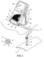
- the wet steam supply device 1 shows a device integrated in a portable hand-held device for detecting the Steam wetness from saturated steam.
- the device is via a wet steam supply device 1 connectable to a threaded connector of a steam line 3.
- the wet steam supply device 1 is designed here as an elastic hose line 4.
- the elastic Hose line 4 comprises an insulation jacket 5 and one accommodated therein Pressure hose 6. Coaxial inside the pressure hose 6 is one Steam line 7 added, which is supported by spacers 8 in the steam line 7 is. There is an intermediate space between the steam line 7 and the pressure hose 6 9 defines the permanent with the steam atmosphere inside the steam line 3 communicates.
- the steam line 7 opens at one end into a probe tube 10 which is in the measuring position protrudes into the steam line 3.
- the hose line 4 has one End of a threaded sleeve 11, by means of which the hose line in sealing Can be attached to the threaded connector 2.
- the wet steam supply device 1 is at its end facing away from the steam line 3 directly connected to a cooling device 12. Inside the cooler 12, the wet steam supplied via the wet steam supply device 1 is cooled and condenses.
- the cooling device 12 is via a cooling fluid supply line 13 and via a cooling fluid drain line 14 into one formed in the handheld device Integrated cooling circuit.
- the cooling device 12 is embedded in an insulating material body 15, an immediate heat exchange between the cooling device 12th and the environment. From this insulating body 15 is a cooling water inlet temperature measuring line 16 and a cooling water outlet temperature measuring line 17 brought out. Both the inlet temperature measuring line 16 and the Output temperature measuring line 17 each include two lead wires, which are inside the cooling device 12 are each connected to a thermocouple. Each The cooling fluid flows directly around the thermocouple (not shown here).
- the input temperature measuring line 16 and the output temperature measuring line 17 are connected to an electronic measuring circuit.
- the analog measured values of the thermocouples acquired via the measuring lines 16 and 17 are each by an A / D converter integrated in the electronic measuring circuit captured by a computer device 19. Inside the handheld device is one device for detection described in more detail below in connection with FIG of the mass flow currently discharged from the cooling device 12. Furthermore, there is a device for detection inside the measuring device of the cooling fluid mass flow conveyed by the cooling device 12 is provided. Based on the detected cooling fluid mass flow, the detected instantaneous Condensate mass flow and that measured via the measuring lines 16 and 17 Cooling fluid inlet temperatures or cooling fluid outlet temperature is in connection with a storage device assigned to the computing device Map of the instantaneous value of the steam wetness calculated. This instantaneous value the steam wetness is displayed on an LCD display surface 20. Furthermore, the The time course of the steam wetness is recorded and stored. The time course of all Measured variables processed by the computer device can also be on the LCD display area 20 are shown.
- the condensate that is continuously deposited in the cooling device 12 is fed via a Branch device branched off from the cooling fluid circuit integrated in the hand-held device and led out of the handheld device via a drain line 21.
- the drain pipe 21 is designed as an elastic hose and opens into a handheld device adjacent collecting vessel 22.
- the collecting vessel shown here has a Capacity of preferably 0.5 liters.
- the collecting vessel 22 is with a Measuring scale 23 provided for reading the condensate volume collected in the collecting vessel.
- the computer device of the handheld device shown here is determined on the basis of the permanently recorded instantaneous condensate mass flow the total amount of condensate discharged through integral formation. Based on the in the condensate volume collected and the by the computer device The integral value determined can easily determine the correctness or the accuracy of the mass flow detection can be checked.
- the measuring circuit used in the hand-held device described above corresponds in its construction essentially the measuring circuit shown in simplified form in FIG.
- the cooling device 12 is completely surrounded by the insulating body 15.
- the cooling device 12 is via the cooling fluid supply line 13 and the cooling fluid outflow line 14 integrated into a cooling fluid circuit arrangement 24.
- a heat exchanger device 25 which includes, for example, a blower device or, as shown here, hermetically connected to an external coolant circuit is.
- the amount of heat removed by the heat exchange device 25 is continuously adjustable in an advantageous manner.
- the heat exchanger device 25 can, for example, the air flow rate one Blower device or the amount of fluid one through the heat exchanger device 25 circulating external fluids can be regulated.
- the regulation of the cooling capacity of the Heat exchanger device 25 is advantageously carried out by means of a computer-controlled Regulatory body.
- a circulation pump 26 For circulating the cooling fluid received in the cooling fluid circuit arrangement 24 a circulation pump 26 is provided.
- the circulation pump 26 can be a hydrostatic or be designed as a hydrodynamic pump.
- the relationship of the cooling fluid flow conveyed by the cooling circuit arrangement 24 to the condensate flow deposited in the cooling device 12 is more advantageous Way in the range of 15: 1.
- the cooling circuit arrangement 24 further comprises one of the circulation pump 26 in the direction of flow sequentially arranged first throttle device 27, its flow resistance is continuously adjustable.
- a second throttle device 28 is immediate provided in the inlet area of the cooling device 12 for further throttling of the cooling fluid flow supplied to the cooling device 12.
- a cooling fluid mass flow detection device 29 is provided for detection of the cooling device 12 supplied cooling fluid mass flow.
- a mixing chamber 30 is formed, in which the Wet steam supply device 1 of the cooling device 12 is supplied with the steam cooling fluid circulating through the cooling fluid circuit assembly 24 contacts. Of the steam coming into contact with the cooling fluid in the mixing chamber 30 is removed by the Cooling fluid cooled and condensed. The condensate that forms is mixed in the cooling fluid continuously conveyed through the mixing chamber 30 and is via the Cooling fluid discharge line 14 discharged from the cooling device 12. From the cooling fluid circuit arrangement 24 fluid is permanently branched off via a fluid branch point. Of the Mass flow of branched fluid corresponds essentially to that in the Cooling device 12 precipitating condensate mass flow. The one about the Fluid mass flow branched off fluid branch point is by means of a control valve device 32 regulated.
- the control valve device 32 is advantageously controlled Way through the computer device provided for the calculation of the steam wetness 19.
- the control strategy for controlling that withdrawn from the cooling fluid circuit arrangement Fluid mass flow advantageously takes into account that at the entrance the cooling device 12 by an inlet temperature sensor 33 and at the outlet the cooling device 12 detected by an output temperature sensor 34 Temperature difference. In the case of small temperature differences, the cooling fluid circuit arrangement 24 withdrawn mass flow increased. This enlarges that flowing in the mixing chamber 30 through the wet steam supply device 1 Steam cooling surface available for cooling.
- the one from the Cooling fluid circuit arrangement 24 withdrawn mass flow can be set to a value be, in which the output temperature sensor 34 a predetermined Maximum temperature value recorded.
- the regulation of the wet steam supply device the amount of steam supplied to the cooling device or the regulation of the cooling device 12 supplied heating power can alternatively to a regulation of the branch mass flow also by controlling the cooling fluid circuit arrangement 24 circulating cooling fluid mass flow take place. This is done more advantageously Way a control of the delivery rate of the circulation pump 26 or a change the setting of the first or second throttle devices 27, 28, likewise as specified by the computer device 19.
- the wet steam supply device 1 comprises similar to the embodiment acc.
- Fig. 1 shows a steam line 7, which forms a gap 9 is arranged in a pressure hose 6. It is via a valve device 39 possible to set a predetermined steam flow in the space 9, wherein the steam discharged from the steam system through the intermediate space 9 via a Outlet line 40 is released to the environment.
- the steam flow in the space 9 is advantageously set to a value sufficient to to compensate for the amount of heat given off to the environment via the pressure hose 6.
- the arrangement made in this way advantageously prevents that a temperature gradient between the inner wall and the outer wall of the steam line 7 and associated with any loss of heat.
- the computer device 19 processes a cooling water inlet temperature T kw detected via the A / D converter 35, a temperature of the mixture of cooling water and condensate detected via the A / D converter 36, the condensate mass flow detected by the condensate mass flow detection device 41, the via the Cooling fluid mass flow detection device 29 detected cooling fluid mass flow and the vapor pressure detected via the pressure detection device 37.
- the computer device calculates the instantaneous value of the steam wetness or the steam content X.
- the calculated values and, if applicable, all the measured values detected by the aforementioned detection devices can be displayed on the display device 20 ′, which is shown here in simplified form.
- the pressure of the (wet) steam it is also possible based on the temperature of the steam to determine the respective enthalpy values h 'and h' '. Furthermore, it is it is also possible to use the enthalpy values h 'and h' 'on the basis of the fluid branch point to determine branched mass flow, since this with appropriate Design of the measuring arrangement essentially proportional to the pressure of the Steam in the steam line 7 is. In order to measure the dampness of steam as precisely as possible to enable the wet steam supply line 1 in an advantageous manner as possible briefly trained.
- FIG. 3 a piece of pipe is shown, which is used for measuring the steam wetness of steam a corresponding steam line can be screwed in.
- This piece of pipe is from one Isolier Sciences 43 surrounded.
- the to record the heating power of the Steam line 3 flowing steam provided cooling device 12 is the pipe section 42 arranged immediately adjacent.
- the steam vapor determination, Partial steam quantity branched off from the system steam line 3 becomes the cooling device 12 via the steam line 7 and that provided in its entry area Probe tube 10 supplied.
- the cooling device 12 is also in an insulating body 15 embedded.
- To record the cooling water inlet temperature is immediately in the Input area of the cooling device 12 of the input temperature sensor 33 is arranged.
- the output temperature sensor 34 is arranged in the cooling fluid drain line 14.
- the cooling device 12 is outside of the steam atmosphere to be examined, the one to be analyzed Part of the steam via a steam line outside the steam system arranged cooling device is supplied.
- Alternative to these embodiments it is, as shown in simplified form in FIG. 4, also possible to use the cooling device in to introduce the steam atmosphere to be analyzed.
- probe assembly is the cooling device 12 in embedded an insulating body 15 formed into a probe head, from which the probe tube 10 protrudes.
- the mixing chamber 30 formed with the cooling fluid supply line 13 and the cooling fluid drain line 14 communicates.
- the output temperature sensor is in the cooling fluid drain line 14 34 arranged. This output temperature sensor 34 is over two lead wires connected to the computing device (not shown here).
- Inside the Mixing chamber 30 occurs via the probe tube 10 of the mixing chamber Steam in contact with the cooling fluid supplied via the cooling fluid supply line 13 and condenses. The mixture of condensate and supplied cooling fluid is passed through the cooling fluid drain line 14 discharged.
- the temperature of the cooling fluid supplied via the cooling fluid supply line 13 by a temperature sensor arranged outside the steam line 3 is detected, it is advantageously also possible to similar this temperature sensor such as the temperature sensor 34 shown here immediately before the mixing chamber 30 to arrange.
- the mixing chamber integrated here in a probe head 12 in an advantageous manner as the mixing chamber shown in Figure 2 in a corresponding cooling fluid circuit arrangement integrated.
- the probe tube 10 is preferred from a material of low thermal conductivity, in particular one Made of ceramic material.
- the measurement of the coolant flow m Kw flowing to the cooling device 12 is carried out by the cooling fluid mass flow detection device 29.
- the inlet temperature sensor (not shown here) is arranged in the cooling fluid supply line 13 (see FIG. 2, reference number 33).
- the temperature of the mixture of cooling fluid and condensate is detected by the output temperature sensor (cf. FIG. 2, reference number 34), which is also not shown here. It is also possible to measure the condensate temperature and the cooling fluid outlet temperature using two separate temperature sensors.
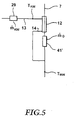
- a particularly precise detection of the condensate mass flow can be advantageous Can be achieved in that the condensate mass flow detection device provided according to Figure 5 in combination with a Fig.2 to the cooling fluid circuit arrangement connected condensate mass flow measuring device 41 is used.
- the method described above and the one described above Devices are found in accordance with a particular aspect of the present invention a steam sterilization process application.
- This is advantageously in Entry area of a steam line into a sterilization chamber from this steam line or a constant low steam flow from the sterilization chamber (e.g. 1kg / h) branched off and fed to a cooling device, the steam supplied condensed in the cooling device.
- the one that is currently reflected in the cooling device Condensate mass flow as well as that carried along with the branched steam Heating power is recorded and, based on these two measured values, the instantaneous steam content or the instantaneous value of the steam wetness is calculated.
- a warning signal is generated.
- the one flowing into the sterilization chamber Steam permanently with regard to its steam content or with regard to monitors his steam wetness.
- the measured values obtained here can be determined using a Writing device recorded or stored in a storage device and, if necessary, can be read out at a later time.
- the invention is not restricted to the exemplary embodiments described above.
- an organic fluid in particular, as the cooling fluid Alcohol
Landscapes
- Physics & Mathematics (AREA)
- Health & Medical Sciences (AREA)
- Life Sciences & Earth Sciences (AREA)
- Chemical & Material Sciences (AREA)
- Analytical Chemistry (AREA)
- Biochemistry (AREA)
- General Health & Medical Sciences (AREA)
- General Physics & Mathematics (AREA)
- Immunology (AREA)
- Pathology (AREA)
- Investigating Or Analyzing Materials Using Thermal Means (AREA)
Abstract
Die Erfindung betrifft ein Verfahren zur Bestimmung des kalorischen Zustandes von Dampf, insbesondere zur Bestimmung der Dampfnässe von Naßdampf sowie eine Vorrichtung hierzu. Erfindungsgemäß wird eine Naßdampf-Teilmenge kontinuierlich einer Kühleinrichtung zugeführt und kondensiert, wobei das sich dabei bildende Kondensat kontinuierlich aus der Kühleinrichtung abgeführt wird. Der Massenstrom des abgeführten Kondensates und die gleichzeitig durch den Naßdampf der Kühleinrichtung zufließende Heizleistung werden erfaßt und basierend auf dem Kondensat-Massenstrom und der erfaßten momentanen Heizleistung der Momentanwert der Dampfnässe errechnet. <IMAGE>The invention relates to a method for determining the caloric state of steam, in particular for determining the steam wetness of wet steam, and a device therefor. According to the invention, a partial amount of wet steam is continuously fed to a cooling device and condensed, the condensate formed in the process being continuously removed from the cooling device. The mass flow of the discharged condensate and the heating power flowing simultaneously through the wet steam to the cooling device are recorded and the instantaneous value of the steam wetness is calculated on the basis of the condensate mass flow and the detected current heating power. <IMAGE>
Description
Die Erfindung betrifft ein Verfahren und eine Vorrichtung zur Erfassung des kalorischen Zustandes von Dampf, insbesondere zur Bestimmung der Dampfnässe von Naßdampf.The invention relates to a method and a device for detecting the caloric Condition of steam, in particular for determining the steam wetness of Wet steam.
Als Naßdampf wird im folgenden ein Dampf-Medium bezeichnet, das nur zum Teil aus gesäftigtem Dampf besteht. Der Anteil der Masse des gesättigten Dampfes an der gesamten Masse des Dampfes wird als Dampfgehalt "X" bezeichnet. Der Wert "1-X" wird im folgenden als Dampfnässe des Naßdampfes bezeichnet.In the following, wet steam is referred to as a steam medium that only partially consists of saturated steam. The proportion of the mass of saturated steam in the total mass of steam is referred to as steam content "X". The value "1-X" is referred to below as the wetness of wet steam.
Die Erfassung des kalorischen Zustandes von Dampf ist bei technischen Anwendungen, beispielsweise der Verwendung von Dampf als Arbeitsmedium in Maschinen, bei der Verwendung von Dampf bei chemischen Prozessen, und insbesondere bei der Verwendung von Dampf als Heizmedium von Bedeutung.The recording of the caloric state of steam is in technical applications, for example the use of steam as a working medium in machines the use of steam in chemical processes, and in particular in the Use of steam as a heating medium is important.
Handelt es sich bei diesem Dampf ausschließlich um Sattdampf oder überhitzten Dampf, so ist der kalorische Zustand des Dampfes eindeutig durch Druck und Temperatur bestimmt.Is this steam exclusively saturated steam or overheated? Steam, the caloric state of the steam is clear from pressure and temperature certainly.
Besteht das Dampf-Medium nur zum Teil aus Sattdampf, so ist der kalorische Zustand dieses Dampf-Mediums durch die Angabe des Dampfgehaltes (X) zusätzlich zu Druck und Temperatur eindeutig bestimmt.If the steam medium consists only partly of saturated steam, the caloric state is this steam medium by specifying the steam content (X) in addition to pressure and temperature clearly determined.
Der kalorische Zustand von Naßdampf läßt sich bei zu erwartenden hohen Werten von X auf einfache Weise dadurch ermitteln, daß der Dampf durch adiabate Drosselung auf einen Heißdampfzustand entspannt wird. Durch Messung von Druck und Temperatur dieses Heißdampfes sowie unter Berücksichtigung des im Rahmen der adiabaten Drosselung durchlaufenen Druckgefälles kann auf den kalorischen Zustand des vor der adiabaten Drosselung vorliegenden Naßdampfes geschlossen werden. The caloric state of wet steam can be expected at high values of X in a simple way that the steam by adiabatic throttling is relaxed to a superheated steam state. By measuring pressure and Temperature of this superheated steam as well as taking into account the Adiabatic throttling through the pressure gradient can be based on the caloric state of the pre-adiabatic throttling Wet steam can be closed.
Bei einem Dampfgehalt von üblicherweise weniger als 0,95 % und einem Dampfdruck von weniger als 10bar ist es möglich, zur Erfassung des Dampfgehaltes eine Teildampfmenge in ein Gefäß zu leiten, daß mit einer vorgegebenen Menge kalten Wassers gefüllt ist. Der zugeführte Dampf kondensiert und füllt allmählich das Gefäß. Anhand des Gefäßfüllstandes und der Temperatur des Wassers in dem Gefäß kann über eine Referenztabelle der Dampfgehalt des untersuchten Dampfes bestimmt werden.With a steam content of usually less than 0.95% and a steam pressure of less than 10bar it is possible to record a steam content Partial amount of steam into a vessel that cold with a predetermined amount Water is filled. The steam supplied condenses and gradually fills the vessel. Based on the level of the vessel and the temperature of the water in the vessel the steam content of the examined steam is determined using a reference table become.
Die Meßgenauigkeit der bekannten Verfahren kann durch Vergrößerung der zur Dampf-Analyse abgezweigten Teildampfmengen gesteigert werden.The measuring accuracy of the known methods can be increased by increasing the Steam analysis branched partial steam quantities can be increased.
Das Abzweigen der zur Analyse vorgesehenen Dampfmengen stellt jedoch einen Eingriff in das zu analysierende Dampfsystem dar, dessen Auswirkungen auf die Aussagefähigkeit der gewonnenen Meßergebnisse nur schwer abschätzbar sind. Durch das Abzweigen der zur Durchführung der üblichen Meßverfahren erforderlichen Dampfmengen ergeben sich je nach Ausführungsform des Dampfversorgungssystemes Abweichungen zwischen der ermittelten Dampfnässe und der in dem System unter ungestörten Betriebsbedingungen herrschenden Dampfnässe.The branching off of the amounts of steam intended for analysis, however, represents a problem Intervention in the steam system to be analyzed, its effects on the meaningfulness the measurement results obtained are difficult to estimate. By the branching of those necessary to carry out the usual measuring procedures Amounts of steam result depending on the embodiment of the steam supply system Deviations between the determined vapor wetness and that in the system Steam moisture prevailing in undisturbed operating conditions.
Im Hinblick auf die vorangehend dargelegte Problematik liegt der Erfindung die Aufgabe zugrunde, ein Verfahren anzugeben, das eine präzise Bestimmung des an einem Untersuchungsort tätsächlich vorliegenden Dampfzustandes, insbesondere im Hinblick auf die Dampfnässe ermöglicht.In view of the problems set out above, the object of the invention is based on specifying a method which enables a precise determination of the on a Examination location of the actual vapor state, especially in the With regard to the dampness of the steam.
Diese Aufgabe wird erfindungsgemäß durch das im Patentanspruch 1 angegebene
Verfahren gelöst.This object is achieved by the one specified in
Dadurch wird es auf vorteilhafte Weise möglich, durch Abzweigen von vergleichsweise geringen Dampfmengen, beispielsweise von weniger als 1 kg/h die Dampfnässe und den kalorischen Zustand des Dampfes in einem Dampfsystem, beispielsweise einer Versorgungsleitung kontinuierlich und im wesentlichen rückwirkungsfrei zu überwachen. Durch das erfindungsgemäße Verfahren wird es insbesondere möglich, anhand kleiner kontinuierlich abgezweigter Massenströme zeitliche Änderungen der Dampfnässe zu erfassen und aufzuzeichnen.This makes it possible in an advantageous manner by branching off comparatively small amounts of steam, for example less than 1 kg / h the steam wetness and the caloric state of the steam in a steam system, for example one Monitor the supply line continuously and essentially without interference. The method according to the invention makes it possible, in particular, based on small continuously branched mass flows changes over time Record and record steam moisture.
In vorteilhafter Weise wird der Momentanwert der Dampfnässe auf Grundlage des Momentanwertes des Kondensat-Massenstromes und dem Momentanwert der der Kühleinrichtung zufließenden Heizleistung in Verbindung mit dem über eine Druckerfassungseinrichtung erfaßten Druck des vorliegenden Dampfes ermittelt. Alternativ zu der Erfassung des Druckes des Dampfes ist es auch möglich, die Temperatur des Dampfes zu erfassen und anhand der erfaßten Temperatur in Verbindung mit dem momentanen Kondensatmassenstrom und der momentanen Heizleistung den Momentanwert der Dampfnässe zu bestimmen. Es ist auch möglich, sowohl die Temperatur als auch den Druck des Dampfes zu erfassen, wobei durch die kombinierte Berücksichtigung dieser beiden Größen eine besonders genaue Ermittlung des Momentanwertes des Dampfzustandes, insbesondere der Dampfnässe möglich wird.The instantaneous value of the steam wetness is advantageously based on the Instantaneous value of the condensate mass flow and the instantaneous value of the Cooling device inflowing heat output in connection with that via a pressure detection device detected pressure of the steam present. alternative to the detection of the pressure of the steam, it is also possible to adjust the temperature of the Detect steam and based on the detected temperature in connection with the instantaneous condensate mass flow and the instantaneous heating power the instantaneous value to determine the steam wetness. It is also possible to change both the temperature as well as the pressure of the steam, taking into account the combined consideration a particularly precise determination of the instantaneous value of these two variables the steam state, especially the steam wetness is possible.
Der der Kühleinrichtung zuströmende Naßdampf wird kontinuierlich kondensiert und die hierbei zugeführte Energie wird permanent durch die Kühleinrichtung abgeführt. Hierzu wird die Kühleinrichtung in vorteilhafter Weise kontinuierlich von einem Kühlfluid durchströmt, wobei die Ausgangstemperatur des Kühlfluides nach Durchlauf der Kühleinrichtung erfaßt wird. In vorteilhafter Weise wird auch die Eingangstemperatur des Kühlfluides vor Eintritt in die Kühleinrichtung erfaßt. Auf die Erfassung der Eingangstemperatur des Kühlfluides vor Eintritt in die Kühleinrichtung kann dann verzichtet werden, wenn anderweitig sichergestellt ist, daß die Eingangstemperatur des Kühlfluides auf einem vorbestimmten Wert gehalten wird. Auf Grundlage der bekannten Eingangstemperatur des Kühlfluides und der erfaßten Ausgangstemperatur des Kühlfluides kann unter Messung des Kühlfluid-Massenstromes die der Kühleinrichtung durch den Naßdampf zugeführte Heizleistung bzw. der momentane Wärmestrom erfaßt werden.The wet steam flowing to the cooling device is continuously condensed and the energy supplied here is permanently dissipated by the cooling device. For this purpose, the cooling device is advantageously continuously cooled by a cooling fluid flows through, the outlet temperature of the cooling fluid after passage of the Cooling device is detected. The inlet temperature is also advantageous of the cooling fluid detected before entering the cooling device. On the detection of the inlet temperature of the cooling fluid before entering the cooling device can then be dispensed with if it is otherwise ensured that the inlet temperature of the cooling fluid is kept at a predetermined value. Based on the known Input temperature of the cooling fluid and the detected output temperature of the cooling fluid can measure the cooling device by measuring the cooling fluid mass flow detected by the wet steam supplied heating power or the instantaneous heat flow become.
Anhand der erfaßten Heizleistung kann in Verbindung mit dem momentanen Kondensatmassenstrom die spezifische Enthalpie des der Kühleinrichtung zuströmenden Naßdampfes ermittelt werden. Anhand der ermittelten momentanen spezifischen Enthalpie des zuströmenden Naßdampfes und dem momentanen Druck oder Temperaturwert kann die momentane Dampfnässe des Naßdampfes errechnet werden. Die Errechnung der Dampfnässe aus der momentanen spezifischen Enthalpie und dem momentan gemessenen Druck oder Temperaturwert kann anhand einer Näherungsfunktion oder unter Rückgriff auf ein Kennfeld erfolgen, die bzw. das im wesentlichen den in dem h-s-Diagramm nach Mollier dargelegten Zusammenhängen Rechnung trägt.On the basis of the detected heating power in connection with the current condensate mass flow the specific enthalpy of the flowing to the cooling device Wet steam can be determined. Based on the determined specific enthalpy of the incoming wet steam and the current pressure or temperature value the instantaneous wetness of the wet steam can be calculated. The Calculation of the steam wetness from the current specific enthalpy and the The currently measured pressure or temperature value can be determined using an approximation function or using a map, which or the essence the correlations set out in the Mollier h-s diagram wearing.
Eine gemäß einem besonderen Aspekt der vorliegenden Erfindung besonders vorteilhafte Ausführungsform des Verfahrens ist dadurch gegeben, daß der der Kühleinrichtung zugeführte Dampf mit dem Kühlfluid in Kontakt tritt. Dadurch wird ein besonders rascher Wärmeübergang und ein rasches Kondensieren des Naßdampfes möglich. Zudem kann auf vorteilhafte Weise auf eine separate Ableitung des in der Kühleinrichtung gebildeten Kondensates verzichtet werden. Ferner wird es möglich, auf eine separate Erfassung der Ablauftemperatur des Kondensates zu verzichten.A particularly advantageous according to a particular aspect of the present invention Embodiment of the method is given in that the cooling device supplied steam comes into contact with the cooling fluid. This makes it special rapid heat transfer and rapid condensation of the wet steam possible. In addition, a separate derivation of the in the cooling device can be advantageous formed condensates are dispensed with. It also becomes possible to have a separate Dispensing with the discharge temperature of the condensate.
Zum Mischen des der Kühleinrichtung zuströmenden Dampfes mit dem der Kühleinrichtung zugeführten Kühlfluid ist im Inneren der Kühleinrichtung in vorteilhafter Weise eine Kühlstrecke ausgebildet, innerhalb welcher sich der zuströmende Naßdampf abkühlt, wobei der sich abkühlende Dampf permanent durch den Druck des Dampfsystems zu der Kühlstrecke hin vorgetrieben wird, vollständig kondensiert und das entstehende Kondensat sich in das Kühlfluid mischt. Unmittelbar im Anschluß an den Mischbereich wird die Temperatur der Fluidmischung aus Kühlfluid und Kondensat erfaßt. Dadurch wird es auf vorteilhafte Weise möglich, die Auswirkungen etwaiger Wärmeverluste nach der Kühleinrichtung auf die Bestimmung der Dampfnässe zu verringern.For mixing the steam flowing into the cooling device with that of the cooling device Cooling fluid supplied is advantageously inside the cooling device a cooling section is formed, within which the incoming wet steam cools down, the cooling steam permanently by the pressure of the steam system is driven to the cooling section, fully condensed and the resulting Condensate mixes in the cooling fluid. Immediately after the The mixing range is the temperature of the fluid mixture of cooling fluid and condensate detected. This advantageously makes it possible to reduce the impact Heat losses after the cooling device towards the determination of the steam wetness reduce.
Eine unter labortechnischen Gesichtspunkten besonders günstig durchführbare Ausführungsform des Verfahrens ist dadurch gegeben, daß das Kühlfluid durch einen Kühlkreislauf zirkuliert, der die Kühleinrichtung und eine Wärmetauscheinrichtung umfaßt, wobei die Wärmetauscheinrichtung das Kühlfluid auf die genannte Eingangstemperatur abkühlt. Dadurch wird es auf vorteilhafte Weise möglich, auf eine permanente Kühlfluidzufuhr von außen sowie auf eine permanente Abfuhr dieses Kühlfluides zu verzichten. Dieser Kühlkreislauf ist, abgesehen von dem in der Kühleinrichtung ggf. vorgesehenen Mischbereich, ein an sich geschlossener Kühlkreislauf, in dem ein vorbestimmtes Kühlfluidvolumen aufgenommen ist.An embodiment which can be carried out particularly inexpensively from a laboratory point of view the method is given in that the cooling fluid through a Cooling circuit circulates, the cooling device and a heat exchange device comprises, wherein the heat exchange device, the cooling fluid to said inlet temperature cools down. This makes it possible in an advantageous manner, on a permanent basis Cooling fluid supply from outside as well as permanent removal of this cooling fluid to renounce. This cooling circuit is apart from that in the cooling device If applicable, the intended mixing area, a cooling circuit that is closed per se, in which a predetermined cooling fluid volume is added.
Für die Ausführungsform des Verfahrens, bei der eine Untermischung des Naßdampfkondensates unter das Kühlfluid vorgesehen ist, wird aus dem Kühlkreislauf in vorteilhafter Weise permanent Fluid abgezweigt. Der Massenstrom des permanent aus dem Kühlkreislauf abgezweigten Fluides entspricht im wesentlichen dem zur gleichen Zeit sich in das Kühlfluid untermischenden Kondensatmassenstrom. Dieser Kondensatmassenstrom wird in vorteilhafter Weise im wesentlichen konstant gehalten. Dies wird auf vorteilhafte Weise dadurch erreicht, daß der aus dem Kühlkreislauf abgezweigte Fluidstrom konstant gehalten wird. Auf vorteilhafte Weise wird es dadurch möglich, indirekt den Massenstrom des der Kühleinrichtung zuströmenden Dampfes zu steuern, da bei ungenügendem Abzug von Fluid aus dem Kühlkreislauf der in der Kühleinrichtung gebildete Mischbereich "überläuft", wodurch sich die zur Abkühlung des zuströmenden Dampfes wirksame Kühlfläche verringert und zwangsläufig weniger Kondensat gebildet wird. Die Menge des aus dem Kühlkreislauf abgezogenen Fluides muß nicht permanent konstant gehalten werden, sondern kann insbesondere durch eine Recheneinrichtung nach Maßgabe einer vorgegebenen Regelstrategie eingeregelt werden.For the embodiment of the method in which the wet steam condensate is mixed in is provided under the cooling fluid, the cooling circuit in advantageously branched fluid permanently. The mass flow of the permanent Fluid diverted from the cooling circuit essentially corresponds to the same Time in the cooling fluid mixed in condensate mass flow. This Condensate mass flow is advantageously kept essentially constant. This is achieved in an advantageous manner in that the cooling circuit branched fluid flow is kept constant. It will be advantageous possible, indirectly the mass flow of the cooling device To control steam because there is insufficient removal of fluid from the cooling circuit the mixing area formed in the cooling device "overflows", as a result of which the Cooling of the incoming steam reduces the effective cooling surface and inevitably less condensate is formed. The amount drawn from the cooling circuit Fluids do not have to be kept constantly constant, but can in particular by a computing device in accordance with a predetermined control strategy be regulated.
Das aus dem Kühlkreislauf abgezogene Fluid oder das sich in der Kühleinrichtung bildende Kondensat wird in vorteilhafter Weise auf seinen Gehalt an nicht-kondensierbaren Gasen hin analysiert. Dadurch wird es insbesondere bei volumetrischer Messung des Kondensat-Massenstromes möglich, etwaige, durch Gaseinschlüsse hervorgerufene Meßfehler bei der Bestimmung des Massenstromes auszuschalten. In vorteilhafter Weise ist eine Entlüftungseinrichtung vorgesehen, durch welche etwaige nicht-kondensierbare Gase abgezweigt werden können. Diese Entlüftungseinrichtung ist in vorteilhafter Weise in Kühlfluid-Strömungsrichtung der Kühleinrichtung abfolgend angeordnet.The fluid withdrawn from the cooling circuit or the fluid that forms in the cooling device Condensate is advantageously based on its content of non-condensable Gases analyzed. This makes it particularly useful for volumetric measurements of the condensate mass flow possible, possibly caused by gas inclusions Switch off measurement errors when determining the mass flow. In A venting device is advantageously provided, through which any non-condensable gases can be branched off. This venting device is advantageously sequential in the cooling fluid flow direction of the cooling device arranged.
Die Analyse des abgezweigten Fluides oder des gebildeten Kondensates hinsichtlich etwaiger darin enthaltener Anteile nicht-kondensierbarer Gase erfolgt in vorteilhafter Weise unter Verwendung eines Kapilarrohres. In diesem Kapilarrohr bilden die ggf. mit dem Naßdampf mitgeführten, nicht kondensierbaren Gase, Gasblasenabschnitte, wobei die Länge dieser Gasblasenabschnitte direkt proportional zum Volumen der jeweiligen Gasblasenabschnitte ist.The analysis of the branched-off fluid or the condensate formed with regard to any portions of non-condensable gases contained therein are advantageously carried out Way using a capillary tube. In this capillary tube, the with the non-condensable gases, gas bubble sections carried with the wet steam, the length of these gas bubble sections being directly proportional to the volume of the respective one Is gas bubble sections.
Eine im Hinblick auf eine besonders genaue Messung der Dampfnässe vorteilhafte Ausführungsform des Verfahrens ist dadurch gegeben, daß der zur Bestimmung der Dampfnässe abgezweigte Teil des Naßdampfes über eine wärmeisolierte Leitungeinrichtung abgezweigt wird. Dadurch wird eine etwaige Verfälschung der Meßergebnisse durch einen bereits vor der Kühleinrichtung stattfindenden Wärmeaustausch mit der Umgebung weitgehend verhindert.An advantageous one with regard to a particularly precise measurement of the steam wetness Embodiment of the method is given in that the determination of the Part of the wet steam diverted from the steam by means of a heat-insulated line device is branched off. This will falsify the measurement results through a heat exchange that takes place before the cooling device largely prevented the environment.
Gemäß einem besonderen Aspekt der vorliegenden Erfindung wird der zur Bestimmung der Dampfnässe abgezweigte Teil des Naßdampfes über eine Leitungseinrichtung abgezweigt, die durch den Naßdampf selbst außenseitig beheizt ist. Dadurch wird es auf vorteilhafte Weise möglich, die Außenseite der zur Zufuhr des Naßdampfes vorgesehenen Leitung exakt auf die Temperatur des Naßdampfes aufzuheizen, so daß zwischen dem Leitungsinneren und dem Leitungsäußeren keine Temperaturdifferenz vorliegt und kein Wärmeaustausch zwischen dem Medium im Inneren der Leitungseinrichtung und dem die Leitungseinrichtung umgebenden Medium stattfindet. Der Durchmesser der Leitungseinrichtung beträgt vorzugsweise weniger als 3 mm. Die Leitungseinrichtung ist in vorteilhafter Weise aus einem Kunststoffmaterial gefertigt.According to a particular aspect of the present invention, that for determination the part of the wet steam branched off via a line device branched, which is heated on the outside by the wet steam itself. Thereby it becomes possible in an advantageous manner, the outside of the supply of wet steam heat the intended pipe exactly to the temperature of the wet steam, so that there is no temperature difference between the inside and outside of the line is present and there is no heat exchange between the medium inside the Line device and the medium surrounding the line device takes place. The diameter of the line device is preferably less than 3 mm. The line device is advantageously made of a plastic material manufactured.
Der über die Leitungseinrichtung abgezweigte Dampf strömt aufgrund eines zwischen der Abzweigstelle und der Kühleinrichtung bestehenden extrem geringen Druckgefälles zu der Kühleinrichtung.The steam branched off via the line device flows due to an intermediate the branching point and the cooling device existing extremely low pressure drop to the cooling device.
Der Leitungsquerschnitt der Leitungseinrichtung ist derart bemessen, daß der abgezweigte Dampf im wesentlichen ungedrosselt in die Kühleinrichtung eintritt. In vorteilhafter Weise wird die Gesamtlänge der Leitungseinrichtung möglichst kurz gehalten.The line cross section of the line device is dimensioned such that the branched Steam enters the cooling device essentially unthrottled. In advantageous The total length of the line device is kept as short as possible.
Der Druck des Kühlfluides in der Kühleinrichtung ist bei einer Ausführungsform des Verfahrens, bei welchem eine Mischung des Kühlfluides und des Naßdampf-Kondensates erfolgt, im wesentlichen gleich dem Druck des durch die Leitungseinrichtung zuströmenden Naßdampfes.The pressure of the cooling fluid in the cooling device is in one embodiment of the Method in which a mixture of the cooling fluid and the wet steam condensate takes place, substantially equal to the pressure of the line device incoming wet steam.
Die Bestimmung des Momentan-Wertes der Dampfnässe erfolgt in vorteilhafter Weise in Verbindung mit einer programmierten Rechnereinrichtung, wobei die Rechnereinrichtung den Momentanwert der Dampfnässe auf Grundlage des momentanen Kondensat-Massenstromes, der momentanen Heizleistung sowie der momentanen Temperatur und/oder dem momentanen Druck des Naßdampfes errechnet. Der zur Berechnung der momentanen Dampfnässe durch die Rechnereinrichtung abgearbeitete Rechenalgorhithmus beinhaltet neben den zur Bestimmung der Dampfnässe erforderlichen Rechenoperationen nach Maßgabe des h-s-Diagrammes nach Mollier in vorteilhafter Weise zusätzliche Korrektur-Terme, die die Wärmekapazität des Meßsystemes und die Druck- und Temperaturabhängigkeit der Dissipationsverluste berücksichtigen.The instantaneous value of the steam wetness is advantageously determined in connection with a programmed computer device, the computer device the instantaneous value of the steam wetness based on the instantaneous condensate mass flow, the current heating output and the current temperature and / or the instantaneous pressure of the wet steam is calculated. The one for calculation the current steam wetness processed by the computer device Computational algorithm includes, in addition to those required to determine the moisture content of the steam Arithmetic operations according to the Mollier h-s diagram advantageously additional correction terms that reflect the thermal capacity of the measuring system and take into account the pressure and temperature dependency of the dissipation losses.
Durch eine effektive Isolierung der Kühleinrichtung kann die Heizleistung des der Kühleinrichtung zuströmenden Dampfes mit hoher Genauigkeit erfaßt werden. Der ggf. durch die Kühleinrichtung abgegebene Verlustwärmestrom kann durch einen entsprechenden Korrekturterm, der beispielsweise die Ausgangs-temperatur der Kühleinrichtung und die Umgebungstemperatur berücksichtigt, weitgehend kompensiert werden.By effectively insulating the cooling device, the heating power of the Cooling device incoming steam can be detected with high accuracy. Of the any lost heat flow emitted by the cooling device can be replaced by a corresponding one Correction term, for example the output temperature of the cooling device and the ambient temperature is taken into account, largely compensated for become.
Für den Fall, daß der der Kühleinrichtung zuströmende Naßdampf sich in der Kühleinrichtung
mit dem Kühlfluid mischt und die Heizleistung des Naßdampfes auf
Grundlage des durch die Kühleinrichtung strömenden Kühlfluidstromes und der Erwärmung
des Kühlfluides gemessen wird, kann der Dampfgehalt X auf Grundlage der
folgenden Gleichung bestimmt werden:
- cpMw
- spez. Wärmekapazität des Mischwassers
- cpKw
- spez. Wärmekapazität des (kalten) Kühlwassers
- mMw
- Massenstrom des Mischwassers = (md+mKw)
- mKw
- Massenstrom des Kühlwassers
- h''d
- Enthalpie des trockenen gesättigten Dampfes
- h'd
- Enthalpie der siedenden Flüssigkeit
- Qverl.
- Wärmestrom aus dem Kondensator durch Isolationsverluste
- ΔT
- Temperaturdifferenz Tmw - TKw
- md
- Massenstrom des Dampfes
- c pMw
- spec. Heat capacity of the mixed water
- c pKw
- spec. Heat capacity of the (cold) cooling water
- m Mw
- Mass flow of mixed water = (m d + m Kw )
- m Kw
- Mass flow of the cooling water
- h " d
- Enthalpy of dry saturated vapor
- h ' d
- Enthalpy of the boiling liquid
- Q ex.
- Heat flow from the condenser due to insulation losses
- ΔT
- Temperature difference T mw - T Kw
- m d
- Mass flow of steam
Die zur Bestimmung des Dampfgehaltes X erforderlichen Werte hd'' sowie hd' sind jeweils eindeutig bestimmten Druck- oder Temperaturwerten zugeordnet und können beispielsweise iterativ aus Näherungsgleichungen oder entsprechenden, vorzugsweise abgespeicherten Kennfeldern entnommen werden.The values h d ″ and h d ′ required for determining the vapor content X are each clearly assigned to certain pressure or temperature values and can be taken, for example, iteratively from approximate equations or corresponding, preferably stored, characteristic maps.
Obgleich die zur Bestimmung der spezifischen Enthalpien h'' und h' erforderlichen Druck- oder Temperaturwerte auf einfache Weise durch eine Druck- oder Temperaturmeßeinrichtung ermittelt werden können, ist es auch möglich, auf eine gesonderte Erfassung des Druckes des Naßdampfes zu verzichten, wobei der Druck indirekt auf Grundlage des aus dem Kühlkreislauf abgezweigten Massenstrom und dem Strömungswiderstand einer den Abzweigmassenstrom begrenzenden Drosselstelle errechnet werden kann.Although necessary to determine the specific enthalpies h '' and h ' Pressure or temperature values in a simple manner by means of a pressure or temperature measuring device can be determined, it is also possible to use a separate Dispensing with the pressure of the wet steam, the pressure being indirect Basis of the mass flow branched off from the cooling circuit and the flow resistance a throttling point limiting the branch mass flow can be.
Hinsichtlich einer Vorrichtung zur Bestimmung der Dampfnässe von Naßdampf wird die eingangs genannte Aufgabe erfindungsgemäß gelöst durch eine Vorrichtung mit einer Naßdampfzufuhr-einrichtung, einer Kühleinrichtung zum Kondensieren einer durch die Naßdampfzufuhreinrichtung zugeführten Naßdampfmenge, einer Kondensatableitungseinrichtung zum Ableiten des Kondensates aus der Kühleinrichtung, einer Kondensatmengen-Erfassungseinrichtung zum Erfassen des Massenstromes des sich bildenden Kondensates, einer Heizleistungserfassungseinrichtung zur Erfassung der Heizleistung des der Kühleinrichtung zugeführten Naßdampfes und einer Rechnereinrichtung zur Berechnung des Momentanwertes der Dampfnässe nach Maßgabe des Kondensat-Massenstromes und der Heizleistung des sich in der Kühleinrichtung niederschlagenden Naßdampfes.With regard to a device for determining the vapor wetness of wet steam the above-mentioned object achieved according to the invention by a device a wet steam supply device, a cooling device for condensing one by the amount of wet steam supplied by the wet steam supply device, a condensate drainage device to drain the condensate from the cooling device, one Condensate quantity detection device for detecting the mass flow of the forming condensate, a heating power detection device for detection the heating power of the wet steam supplied to the cooling device and a computer device for the calculation of the instantaneous value of the steam wetness in accordance with of the condensate mass flow and the heating power of the in the cooling device precipitating wet steam.
Die erfindungsgemäße Vorrichtung ist kleinbauend herstellbar und ermöglicht eine kontinuierliche Analyse des kalorischen Zustandes von Dampf, wobei der kalorische Zustand des Dampfes unter Abzweigung vergleichsweise geringer Teildampfmengen ermittelt werden kann.The device according to the invention can be produced in a compact manner and enables one continuous analysis of the caloric state of steam, the caloric Condition of the steam with the branching off of comparatively small amounts of partial steam can be determined.
In vorteilhafter Weise ist die Kühleinrichtung mit einer Wärmedämmeinrichtung umgeben, zur Unterdrückung eines Wärmeüberganges zwischen der Kühleinrichtung und der Umgebung. Dadurch wird auf vorteilhafte Weise sichergestellt, daß die der Kühleinrichtung zugeführte Heizleistung durch Messung der Erwärmung des Kühlwassers präzise erfaßt werden kann.The cooling device is advantageously surrounded by a thermal insulation device, to suppress heat transfer between the cooling device and the environment. This advantageously ensures that the cooling device supplied heating power by measuring the heating of the cooling water can be recorded precisely.
Die Heizleistungserfassungseinrichtung umfaßt in vorteilhafter Weise eine erste Temperaturmeßstelle zur Erfassung der Kühlfluideingangstemperatur und eine zweite Temperaturmeßstelle zur Erfassung einer Kühlfluidausgangstemperatur. Anhand der Erwärmung des Kühlfluides kann in Verbindung mit dem Massenstrom des Kühlfluides die der Kühleinrichtung zugeführte Heizleistung präzise erfaßt werden.The heating power detection device advantageously comprises a first temperature measuring point to record the cooling fluid inlet temperature and a second Temperature measuring point for recording a cooling fluid outlet temperature. Based on Heating of the cooling fluid can be in connection with the mass flow of the cooling fluid the heating power supplied to the cooling device can be precisely detected.
Eine besonders präzise Erfassung der Heizleistung wird in vorteilhafter Weise dadurch möglich, daß die zweite Temperaturmeßstelle innerhalb der die Kühleinrichtung umgebenden Wärmedämmungseinrichtung angeordnet ist. Dadurch wird es auf vorteilhafte Weise möglich, den Einfluß etwaiger Wärmeverluste in dem Leitungssystem bis zu der genannten zweiten Temperaturmeßstelle nahezu vollständig zu unterdrücken.A particularly precise detection of the heating power is thereby advantageously possible that the second temperature measuring point within the cooling device surrounding thermal insulation device is arranged. This will make it beneficial Possible way, the influence of any heat loss in the pipe system almost completely suppressed up to the second temperature measuring point mentioned.
Eine insbesondere im Hinblick auf eine permanente Überwachung der Dampfnässe vorteilhafte Ausführungsform der Vorrichtung ist dadurch gegeben, daß die Kühleinrichtung in eine Kühlfluidkreislaufanordnung eingebunden ist, wobei das Kühlfluid durch die Kühlfluid-Kreislaufanordnung zirkuliert. Dadurch ist es möglich, die Vorrichtung unabhängig von einer separaten Kühlfluid- insbesondere Kaltwasserquelle zu betreiben. In weiterhin vorteilhafter Weise wird dadurch ermöglicht, daß aus der Vorrichtung lediglich das im Rahmen des Meßbetriebes anfallende Kondensat abgeführt werden muß.One especially with regard to permanent monitoring of the steam wetness advantageous embodiment of the device is given in that the cooling device is integrated into a cooling fluid circuit arrangement, the cooling fluid circulated through the cooling fluid circuit assembly. This makes it possible to use the device independent of a separate cooling fluid - especially cold water source operate. In a further advantageous manner, this enables the device only the condensate generated in the course of the measuring operation is removed must become.
Das Leitungssystem dieser Kreislaufanordnung ist in vorteilhafter Weise derart ausgebildet, daß das Kühlfluid sich bis zum Eintritt in die Kühleinrichtung ausreichend abgekühlt hat. Um eine besonders effektive Abkühlung des Kühlfluides zu ermöglichen, ist in die Kühlfluid-Kreislaufanordnung in vorteilhafter Weise eine Wärmetauscheinrichtung eingefügt. Diese Wärmetauscheinrichtung ermöglicht eine effektive Abfuhr der dem Kühlfluid in der Kühleinrichtung zugeführten Wärme. Der Wärmetauscher umfaßt in vorteilhafter Weise eine Gebläseeinrichtung zur Abkühlung des Kühlfluides durch die Umgebungsluft. Alternativ dazu oder auch in Kombination mit dieser Gebläseeinrichtung ist es auch möglich, den Wärmetauscher mit einer externen Fluidquelle zu verbinden. Bei einer Ausführungsform des Wärmetauschers als Fluidwärmetauscher kann ein Kühlwassereingang beispielsweise im unteren Bereich eines großvolumigen Gefäßes und der Kühlwasserausgang des Wärmetauschers an den oberen Bereich des Gefäßes angeschlossen werden. Durch die Einbindung eines Wärmetauschers in die Kühlfluid-Kreislaufanordnung wird es auf vorteilhafte Weise möglich, das Volumen des in der Kühlfluid-Kreislaufanordnung aufgenommenen Fluides gering zu halten, wodurch sich eine besonders hohe Steifigkeit der Kühlfluidkreislaufanordnung hinsichtlich druckschwankungsbedingter Volumenänderungen ergibt.The line system of this circuit arrangement is advantageously designed in such a way that that the cooling fluid cools sufficiently until it enters the cooling device Has. In order to allow a particularly effective cooling of the cooling fluid, is in the cooling fluid circuit arrangement advantageously a heat exchange device inserted. This heat exchange device enables effective removal the heat supplied to the cooling fluid in the cooling device. The heat exchanger advantageously comprises a blower device for cooling the cooling fluid through the ambient air. Alternatively or in combination with this blower device it is also possible to use an external fluid source for the heat exchanger connect to. In one embodiment of the heat exchanger as a fluid heat exchanger can a cooling water inlet, for example, in the lower area of a large volume Vessel and the cooling water outlet of the heat exchanger at the top Area of the vessel. By integrating a heat exchanger in the cooling fluid circuit arrangement it is advantageously possible the volume of the fluid received in the cooling fluid circuit arrangement is small to maintain, resulting in a particularly high rigidity of the cooling fluid circuit arrangement with regard to changes in volume caused by pressure fluctuations.
Die in der Kühlfluid-Kreislaufanordnung aufgenommene Kühlfluidmenge wird in vorteilhafter Weise durch eine Pumpeneinrichtung umgewälzt. Durch Steuerung der Pumpenleistung bzw. Drehzahl kann hierbei auf vorteilhafte Weise der Massenstrom des durch die Kühleinrichtung strömenden Kühlfluides präzise eingestellt werden. Eine besonders präzise Einstellung des durch die Kühleinrichtung strömenden Kühlfluid-Massenstroms kann durch eine der Pumpeneinrichtung nachgeschaltete Drosseleinrichtung erreicht werden. Durch die Verwendung der Pumpeneinrichtung und eine dieser nachgeschaltete Drosseleinrichtung wird es möglich, das Druckgefälle des Kühlfluides in der Kühleinrichtung auf einem geringen Wert zu halten. The amount of cooling fluid received in the cooling fluid circuit arrangement becomes more advantageous Circulated by a pump device. By controlling the Pump output or speed can advantageously be the mass flow of the cooling fluid flowing through the cooling device can be set precisely. A particularly precise adjustment of the cooling fluid mass flow flowing through the cooling device can by a throttle device downstream of the pump device can be achieved. By using the pump device and a this downstream throttle device, it is possible to reduce the pressure drop To keep cooling fluids in the cooling device at a low value.
In vorteilhafter Weise ist eine Kühlfluidmassenstromerfassungseinrichtung vorgesehen zur Erfassung des der Kühleinrichtung zugeführten Kühlfluid-Massenstromes. Diese Kühlfluidmassenstromerfassungseinrichtung kann beispielsweise durch eine Blendeneinrichtung und eine der Blendeneinrichtung vorgeschaltete Druckerfassungseinrichtung oder beispielsweise auch durch eine volumetrische oder auch hydrodynamische Massen- oder Volumenstromerfassungseinrichtung gebildet sein. In vorteilhafter Weise ist die Kühlfluidmassenstromerfassungseinrichtung in die Pumpeneinrichtung integriert. Die Pumpeneinrichtung kann dabei beispielsweise als Zahnradpumpe oder als Piezo-Pumpe ausgebildet sein. Die Ausbildung der Pumpeneinrichtung als Dosierpumpe macht es möglich, auf eine Messung des Kühlfluidstromes zu verzichten und die durch die Dosierpumpe, beispielsweise auf einen bestimmten Wert festgelegten Volumenstrom durch die Rechnereinrichtung zu berücksichtigen.A cooling fluid mass flow detection device is advantageously provided for detecting the cooling fluid mass flow supplied to the cooling device. This cooling fluid mass flow detection device can, for example, by a Diaphragm device and a pressure detection device upstream of the diaphragm device or for example also by a volumetric or hydrodynamic Mass or volume flow detection device can be formed. In The cooling fluid mass flow detection device is advantageously in the pump device integrated. The pump device can, for example, be a gear pump or be designed as a piezo pump. The formation of the pump device As a metering pump, it makes it possible to measure the cooling fluid flow to dispense with and by the metering pump, for example on a specific Volume flow through the computer device to be taken into account.
Eine im Hinblick auf eine besonders günstige Erfassung der Heizleistung des Naßdampfes vorteilhafte Ausführungsform der Erfindung ist dadurch gegeben, daß in der Kühleinrichtung ein Mischbereich vorgesehen ist, und daß der Naßdampf oder dessen Kondensat in dem Mischbereich mit dem Kühlfluid in Kontakt tritt, wobei die Kühleinrichtung einen Abfluß-Fluidweg aufweist zum Ableiten des Kühlfluides gemeinsam mit dem untergemischten Kondensat. Dadurch wird es auf besonders vorteilhafte Weise möglich, die aus der Kühleinrichtung abgeführte Wärmemenge mittels einer einzigen Temperaturerfassungseinrichtung zu messen. Ferner ist auf vorteilhafte Weise sichergestellt, daß der in der Kühleinrichtung kondensierte Naßdampf und das Kühlfluid die gleiche Temperatur aufweisen. Des weiteren wird es auf besonders vorteilhafte Weise möglich, den Massenstrom des sich in der Kühleinrichtung bildenden Kondensates zu messen.With regard to a particularly favorable detection of the heating power of the wet steam advantageous embodiment of the invention is given in that in the Cooling device, a mixing area is provided, and that the wet steam or its Condensate in the mixing area comes into contact with the cooling fluid, the cooling device has a drain fluid path for draining the cooling fluid together with the mixed condensate. This makes it particularly advantageous Possible way, the amount of heat removed from the cooling device by means of a single temperature detection device to measure. It is also advantageous Way ensured that the wet steam condensed in the cooling device and Cooling fluid have the same temperature. Furthermore, it becomes particularly advantageous Way possible, the mass flow of the formed in the cooling device To measure condensates.
Um das Volumen der in der Kühlfluidkreislaufanordnung aufgenommenen Kühlflüssigkeit konstant zu halten, ist in vorteilhafter Weise eine Abzweigeinrichtung vorgesehen zum Abzweigen von Kühlfluid oder einer Mischung von Kühlfluid und Kondensat aus der Kühlfluidkreislaufanordnung. In vorteilhafter Weise ist die Kondensatmengen-Erfassungseinrichtung an die Abzweigeinrichtung angeschlossen zur Erfassung des aus dem Kühlfluid-Kreislauf abgezweigten Massenstromes. The volume of the cooling liquid received in the cooling fluid circuit arrangement to keep constant, a branching device is advantageously provided for branching off cooling fluid or a mixture of cooling fluid and condensate from the cooling fluid circuit arrangement. The condensate quantity detection device is advantageous to the branching device connected to detect the branched off from the cooling fluid circuit Mass flow.
Die Erfassung der Erwärmung des Kühlfluides erfolgt in vorteilhafter Weise mittels einer Sensoreinrichtung, deren Meßsignal bedarfsweise einer Analog/Digital Wandlereinrichtung zugeführt und in ein von der Rechnereinrichtung lesbares Signal umgewandelt wird. Auch die Eingangstemperatur des Kühlfluides wird über eine Sensoreinrichtung erfaßt und bedarfsweise unter Zwischenschaltung einer Analog/Digital Wandler-einrichtung der genannten Rechnereinrichtung zugeführt.The heating of the cooling fluid is advantageously detected by means of a Sensor device, the measurement signal of which requires an analog / digital converter device supplied and converted into a signal readable by the computer device becomes. The inlet temperature of the cooling fluid is also monitored via a sensor device recorded and if necessary with the interposition of an analog / digital Transducer device of the computer device mentioned.
Die genannte Rechnereinrichtung verarbeitet ferner ein für den Kondensatmassenstrom repräsentatives Signal. Dieses Sig-nal kann bedarfsweise ebenfalls unter Zwischenschaltung einer Analog/Digial Wandlereinrichtung erzeugt werden. Der Kondensatmassenstrom kann auch dadurch erfaßt werden, daß das Kondensat mittels einer Pumpeinrichtung gefördert wird, wobei der Kondensatmassenstrom durch eine Steuereinrichtung vorgegeben wird, und der momentan vorgegebene Kondensatmassenstrom der durch die Rechnereinrichtung durchgeführten Berechnung zugrundegelegt wird.The computer device mentioned also processes a for the condensate mass flow representative signal. If necessary, this signal can also be interposed an analog / digital converter device can be generated. The mass flow of condensate can also be detected by using the condensate a pumping device is conveyed, the condensate mass flow through a Control device is specified, and the currently specified condensate mass flow on the basis of the calculation carried out by the computer device becomes.
In vorteilhafter Weise ist es auch möglich, den Kondensatmassenstrom durch eine Einstellvorrichtung einzustellen. Eine derartige Einstellvorrichtung kann beispielsweise durch ein stufenlos einstellbares Drosselventil gebildet sein. Der jeweils gewünschte Kondensatmassenstrom bzw. der jeweils gewünschte, insbesondere günstigste Massenstrom einer Kondensat/Kühlfluidmischung wird in vorteilhafter Weise auf Grundlage einer vorbestimmten Regelstrategie durch die Rechnereinrichtung ermittelt und automatisch eingeregelt.In an advantageous manner, it is also possible to flow the condensate mass flow through a Adjust the adjustment device. Such an adjustment device can, for example be formed by a continuously adjustable throttle valve. The one you want Condensate mass flow or the respectively desired, in particular cheapest mass flow a condensate / cooling fluid mixture is advantageously based a predetermined control strategy determined by the computer device and automatically adjusted.
Die Rechnereinrichtung umfaßt in vorteilhafter Weise eine Speichereinrichtung, in der ein Datensatz abgespeichert ist, aus dem zu einem vorbestimmten Druck oder Temperaturwert die Enthalpien h' und h'' abgelesen werden können. In vorteilhafter Weise ist eine weitere Speichereinrichtung vorgesehen, in der die über eine bestimmte Zeitdauer hinweg gemessenen Meßwerte und insbesondere der daraus errechnete Wert für den Dampfgehalt bzw. die errechnete Dampfnässe abgespeichert werden. The computing device advantageously comprises a storage device in which a data record is stored from which to a predetermined pressure or temperature value the enthalpies h 'and h' 'can be read. Advantageously a further storage device is provided in which the data is stored over a certain period of time measured values measured and in particular the value calculated therefrom for the steam content or the calculated steam wetness can be saved.
Der Rechenalgorithmus der Recheneinrichtung kann bedarfsweise geändert werden. Die Rechnereinrichtung ist hierzu in vorteilhafter Weise mit einer Schnittstelle versehen.The computing algorithm of the computing device can be changed if necessary. For this purpose, the computer device is advantageously provided with an interface.
Über diese Schnittstelle kann die Rechnereinrichtung mit einer extemen Eingabevorrichtung oder beispielsweise auch mit einem externen Rechnersystem verbunden werden. Für den Fall, daß die Rechnereinrichtung einen Dampfgehalt von 100 % oder mehr ermittelt, wird in vorteilhafter Weise die momentane Überhitzungstemperatur des Dampfes angezeigt. In vorteilhafter Weise ist die Anzeigefläche als Flach-Bildschirm, insbesondere als LCD-Bildschirm, ausgebildet, und die Rechnereinrichtung derart programmiert, daß diese das momentane Dampfzustandumgebungsfeld in dem h-s-Diagramm darstellt, wobei der momentane Dampfzustands-Punkt in diesem graphisch dargestellten h-s-Diagramm kontinuierlich angezeigt wird.The computer device can use this interface with an external input device or, for example, also connected to an external computer system become. In the event that the computing device has a steam content of 100% or more, the instantaneous superheating temperature is advantageously determined of steam is displayed. The display surface is advantageously a flat screen, in particular as an LCD screen, and the computer device programmed to match the current vapor state environment field in the h-s diagram, with the instantaneous vapor state point in this graphically represented h-s diagram is displayed continuously.
In vorteilhafter Weise ist es auch möglich, die Vorrichtung insbesondere über die genannte Schnittstelle in ein Steuerungs- oder Überwachungssystem einzubinden, wodurch es möglich wird, beispielsweise die Heizleistung einer Dampferzeugungseinrichtung im Hinblick auf eine gewünschte Dampfnässe zu steuern.In an advantageous manner, it is also possible to use the device, in particular, via the aforementioned Integrate interface in a control or monitoring system, whereby it becomes possible, for example the heating power of a steam generating device to control with regard to a desired steam wetness.
Die Erfindung wird nachfolgend anhand von Ausführungsbeispielen und zugehörigen Zeichnungen näher erläutert. In diesen zeigen:
- Fig.1
- eine perspektivische Ansicht einer Vorrichtung zur Messung der Dampfnässe nach der Erfindung,
- Fig.2
- eine Prinzip-Skizze zur Erläuterung des Aufbaus einer bevorzugten Ausführungsform einer Meßanordnung nach der Erfindung,
- Fig.3
- eine Längsschnittansicht durch ein isoliertes Rohrleitungsstück mit diesem unmittelbar benachbart angeordneter Kühleinrichtung,
- Fig.4
- eine vereinfachte Längsschnittansicht durch eine Dampfabzweigeinrichtung mit integrierter Kühleinrichtung,
- Fig.5
- eine vereinfachte Darstellung eines Ausschnitts aus einer Meßschaltungsanordnung gemäß einer weiteren Ausführungsform der Erfindung mit separater Kondensatmengenerfassung,
- Fig. 1
- 2 shows a perspective view of a device for measuring the vapor wetness according to the invention,
- Fig. 2
- 2 shows a schematic diagram to explain the structure of a preferred embodiment of a measuring arrangement according to the invention,
- Fig. 3
- 2 shows a longitudinal sectional view through an insulated pipe piece with this cooling device arranged directly adjacent to it,
- Fig. 4
- a simplified longitudinal sectional view through a steam branch device with integrated cooling device,
- Fig. 5
- a simplified representation of a section of a measuring circuit arrangement according to a further embodiment of the invention with separate condensate quantity detection,
Fig.1 zeigt eine in ein tragbares Handgerät integrierte Vorrichtung zur Erfassung der
Dampfnässe von Sattdampf. Die Vorrichtung ist über eine Naßdampfzufuhreinrichtung
1 an einen Gewindestutzen einer Dampfleitung 3 anschließbar. Die Naßdampfzufuhreinrichtung
1 ist hier als elastische Schlauchleitung 4 ausgebildet. Die elastische
Schlauchleitung 4 umfaßt einen Isolationsmantel 5 und einen darin aufgenommenen
Druckschlauch 6. Koaxial im Inneren des Druckschlauches 6 ist eine
Dampfleitung 7 aufgenommen, die über Abstandshalter 8 in der Dampfleitung 7 abgestützt
ist. Zwischen der Dampfleitung 7 und dem Druckschlauch 6 ist ein Zwischenraum
9 definiert, der mit der Dampfatmosphäre im Inneren der Dampfleitung 3 permanent
in Verbindung steht.1 shows a device integrated in a portable hand-held device for detecting the
Steam wetness from saturated steam. The device is via a wet
Die Dampfleitung 7 mündet mit ihrem einen Ende in ein Sondenrohr 10, das in Meßstellung
in die Dampfleitung 3 hineinragt. Die Schlauchleitung 4 weist an ihrem einen
Ende eine Gewindemuffe 11 auf, mittels welcher die Schlauchleitung in abdichtender
Weise an dem Gewindestutzen 2 anbringbar ist.The
Die Naßdampfzufuhreinrichtung 1 ist an ihrem der Dampfleitung 3 abgewandten Ende
unmittelbar an eine Kühleinrichtung 12 angeschlossen. Im Inneren der Kühleinrichtung
12 wird der über die Naßdampfzufuhreinrichtung 1 zugeführte Naßdampf abgekühlt
und kondensiert. Die Kühleinrichtung 12 ist über eine Kühlfluidzufuhrleitung 13
und über eine Kühlfluidabflußleitung 14 in einen in dem Handgerät ausgebildeten
Kühlkreislauf integriert. Die Kühleinrichtung 12 ist in einen Isolierstoffkörper 15 eingebettet,
der einen unmittelbaren Wärmeaustausch zwischen der Kühleinrichtung 12
und der Umgebung verhindert. Aus diesem Isolierstoffkörper 15 ist eine Kühlwassereingangs-temperaturmeßleitung
16 und eine Kühlwasserausgangstemperaturmeßleitung
17 herausgeführt. Sowohl die Eingangstemperaturmeßleitung 16 als auch die
Ausgangsstemperaturmeßleitung 17 umfassen jeweils zwei Leitungsdrähte, die im Inneren
der Kühleinrichtung 12 jeweils an ein Thermoelement angeschlossen sind. Jedes
Thermoelement (hier nicht dargestellt) wird unmittelbar von dem Kühlfluid umspült.
Die Eingangstemperaturmeßleitung 16 und die Ausgangstemperaturmeßleitung
17 sind an eine elektronische Meßschaltung angeschlossen.The wet
Die über die Meßleitungen 16 und 17 erfaßten analogen Meßwerte der Thermoelemente
werden durch jeweils einen in die elektronische Meßschaltung integrierten A/D-Wandler
von einer Rechnereinrichtung 19 erfaßt. Im Inneren des Handgerätes ist eine
nachfolgend in Verbindung mit Fig.2 noch näher beschriebene Einrichtung zur Erfassung
des momentan aus der Kühleinrichtung 12 abgeführten Massenstromes, angeordnet.
Des weiteren ist im Inneren des Meßgerätes eine Einrichtung zur Erfassung
des durch die Kühleinrichtung 12 geförderten Kühlfluidmassenstromes vorgesehen.
Auf Grundlage des erfaßten Kühlfluidmassenstromes, des erfaßten momentanen
Kondensatmassenstromes sowie der über die Meßleitungen 16 und 17 gemessenen
Kühlfluideintrittstemperaturen bzw. Kühlfluidaustrittstemperatur wird in Verbindung mit
einem in einer der Rechnereinrichtung zugeordneten Speichereinrichtung gespeicherten
Kennfeld der Momentanwert der Dampfnässe errechnet. Dieser Momentanwert
der Dampfnässe wird über eine LCD-Anzeigefläche 20 angezeigt. Ferner wird der
zeitliche Verlauf der Dampfnässe erfaßt und gespeichert. Der zeitliche Verlauf sämtlicher
durch die Rechnereinrichtung verarbeiteter Meßgrößen kann ebenfalls auf der
LCD-Anzeigefläche 20 dargestellt werden.The analog measured values of the thermocouples acquired via the measuring
Das sich ständig in der Kühleinrichtung 12 niederschlagende Kondensat wird über eine
Abzweigeinrichtung aus dem in das Handgerät integrierten Kühlfluidkreis abgezweigt
und über eine Ablaßleitung 21 aus dem Handgerät herausgeführt. Die Ablaßleitung
21 ist als elastischer Schlauch ausgebildet und mündet in ein dem Handgerät
benachbart aufgestelltes Auffanggefäß 22. Das hier dargestellte Auffanggefäß hat ein
Fassungsvolumen von vorzugsweise 0,5 Liter. Das Auffanggefäß 22 ist mit einer
Meßskala 23 versehen zum Ablesen des in dem Auffanggefäß aufgefangenen Kondensatvolumens.
Die Rechnereinrichtung des hier dargestellten Handgerätes ermittelt
auf Grundlage des permanent erfaßten momentanen Kondensat-Massenstromes
durch Integralbildung die Gesamtmenge an abgeführtem Kondensat. Anhand des in
dem Auffanggefäß aufgefangenen Kondensatvolumens und des durch die Rechnereinrichtung
ermittelten Integralwertes kann auf einfache Weise die Richtigkeit bzw.
die Genauigkeit der Massenstromerfassung überprüft werden.The condensate that is continuously deposited in the
Die bei dem vorangehend beschriebenen Handgerät verwendete Meß-Schaltung entspricht in ihrem Aufbau im wesentlichen der in Figur 2 vereinfacht dargestellten Meß-Schaltung.The measuring circuit used in the hand-held device described above corresponds in its construction essentially the measuring circuit shown in simplified form in FIG.
Gemäß Fig.2 ist die Kühleinrichtung 12 vollständig von dem Isolierstoffkörper 15 umgeben.
Die Kühleinrichtung 12 ist über die Kühlfluidzufuhrleitung 13 und die Kühlfluidabflußleitung
14 in eine Kühlfluidkreislaufanordnung 24 eingebunden.According to Figure 2, the
In die Kühlfluidkreislaufanordnung 24 ist in vorteilhafter Weise ferner eine Wärmetauschereinrichtung
25 eingebunden, die beispielsweise eine Gebläseeinrichtung umfaßt
oder, wie hier dargestellt, hermetisch getrennt an einen Fremdkühlmittelkreislauf angeschlossen
ist. Die durch die Wärmetauscheinrichtung 25 abgeführte Warmemenge
ist in vorteilhafter Weise stufenlos regelbar. Zur stufenlosen Regelung der Wärmeabfuhr
der Wärmetauschervorrichtung 25 kann beispielsweise der Luftdurchsatz einer
Gebläseeinrichtung oder die Fluidmenge eines durch die Wärmetauschervorrichtung
25 zirkulierenden Fremdfluides geregelt werden. Die Regelung der Kühlleistung der
Wärmetauschervorrichtung 25 erfolgt in vorteilhafter Weise mittels eines rechnergesteuerten
Regelorganes.In the cooling
Zur Umwälzung des in der Kühlfluidkreislaufanordnung 24 aufgenommenen Kühlfluides
ist eine Umwälzpumpe 26 vorgesehen. Die Umwälzpumpe 26 kann als hydrostatische
oder auch als hydrodynamisch fördernde Pumpe ausgebildet sein. Das Verhältnis
des durch die Kühlkreislaufanordnung 24 geförderten Kühlfluidstromes zu dem
in der Kühleinrichtung 12 niedergeschlagenen Kondensatstrom liegt in vorteilhafter
Weise im Bereich von 15 : 1.For circulating the cooling fluid received in the cooling fluid circuit arrangement 24
a
Die Kühlkreislaufanordnung 24 umfaßt ferner eine der Umwälzpumpe 26 in Strömungsrichtung
abfolgend angeordnete erste Drosseleinrichtung 27, deren Strömungswiderstand
stufenlos einstellbar ist. Eine zweite Drosseleinrichtung 28 ist unmittelbar
im Eintrittsbereich der Kühleinrichtung 12 vorgesehen zur nochmaligen Drosselung
des der Kühleinrichtung 12 zugeführten Kühlfluidstromes. Zwischen der ersten
Drosseleinrichtung 27 und der zweiten Drosseleinrichtung 28 ist eine Kühlfluidmassenstromerfassungseinrichtung
29 vorgesehen zur Erfassung des der Kühleinrichtung
12 zugeführten Kühlfluidmassenstromes.The
In der Kühleinrichtung 12 ist eine Mischkammer 30 gebildet, in welcher der über die
Naßdampfzufuhreinrichtung 1 der Kühl-einrichtung 12 zugeführte Dampf mit dem
durch die Kühlfluidkreislaufanordnung 24 zirkulierenden Kühlfluid in Kontakt tritt. Der
mit dem Kühlfluid in der Mischkammer 30 in Kontakt tretende Dampf wird durch das
Kühlfluid abgekühlt und kondensiert. Das sich bildende Kondensat mischt sich unter
das kontinuierlich durch die Mischkammer 30 geförderte Kühlfluid und wird über die
Kühlfluidabflußleitung 14 aus der Kühleinrichtung 12 abgeführt. Aus der Kühlfluidkreislaufanordnung
24 wird permanent über eine Fluidabzweigstelle Fluid abgezweigt. Der
Massenstrom an abgezweigtem Fluid entspricht im wesentlichen dem sich in der
Kühleinrichtung 12 niederschlagenden Kondensat-Massenstrom. Der über die
Fluidabzweigstelle abgezweigte Fluidmassenstrom wird mittels einer Stellventileinrichtung
32 geregelt. Die Regelung der Stellventileinrichtung 32 erfolgt in vorteilhafter
Weise durch die zur Berechnung der Dampfnässe vorgesehene Rechnereinrichtung
19. Die Regelstrategie zur Regelung des aus der Kühlfluidkreislaufanordnung abgezogenen
Fluidmassenstromes berücksichtigt dabei in vorteilhafter Weise die am Eingang
der Kühleinrichtung 12 durch einen Eingangstemperatursensor 33 und am Ausgang
der Kühleinrichtung 12 durch einen Ausgangstemperatursensor 34 erfaßte
Temperaturdifferenz. Im Falle kleiner Temperaturdifferenzen wird der aus der Kühlfluidkreislaufanordnung
24 abgezogene Massenstrom erhöht. Dadurch vergrößert
sich die in der Mischkammer 30 dem durch die Naßdampfzufuhreinrichtung 1 nachströmenden
Dampf zur Abkühlung zur Verfügung stehende Kühlfläche. Der aus der
Kühlfluidkreislaufanordnung 24 abgezogene Massenstrom kann auf einen Wert eingestellt
werden, bei dem der Ausgangstemperatursensor 34 einen vorgegebenen
Temperaturmaximalwert erfaßt. Die Regelung der über die Naßdampfzufuhreinrichtung
der Kühleinrichtung zugeführten Dampfmenge bzw. die Regelung der der Kühleinrichtung
12 zugeführten Heizleistung kann alternativ zu einer Regelung des Abzweigmassenstromes
auch durch Regelung des durch die Kühlfluidkreislaufanordnung
24 zirkulierenden Kühlfluidmassenstromes erfolgen. Hierzu erfolgt in vorteilhafter
Weise eine Steuerung der Förderleistung der Umwälzpumpe 26 oder eine Änderung
der Einstellung der ersten oder zweiten Drosseleinrichtungen 27,28, ebenfalls
gemäß Vorgabe durch die Rechnereinrichtung 19.In the
Die durch den Eingangstemperatursensor 33 und den Ausgangs-temperatursensor
34 erfaßten Meßsignale werden der Rechnereinrichtung 19 unter Zwischenschaltung
jeweils eines A/D-Wandlers zugeführt. Um eine möglichst präzise Bestimmung der zu
dem jeweiligen Dampfdruck korrespondierenden Werte der Sattdampfenthalpie und
der Enthalpie der siedenden Flüssigkeit zu ermöglichen, ist gemäß der in Fig.2 dargestellten
Schaltung eine Druckerfassungseinrichtung 37 vorgesehen, die den in dem
Dampfversorgungssystem herrschenden Dampfdruck erfaßt.That by the
Bei dem vorangehend erläuterten Meßgerät wird der Druck des Dampfversorgungssystems über die Leitung gemessen, die mit dem in Fig.1 dargestellten Zwischenraum 9 in Verbindung steht. Diese Abzweigleitung ist in Fig.2 in Strichlinien dargestellt und durch das Bezugszeichen 38 gekennzeichnet.In the measuring device explained above, the pressure of the steam supply system measured over the line with the space shown in Fig.1 9 communicates. This branch line is shown in dashed lines in FIG identified by reference numeral 38.
Die Naßdampfzufuhreinrichtung 1 gemäß Fig.2 umfaßt ähnlich wie bei dem Ausführungsbeispiel
gem. Fig. 1 eine Dampfleitung 7, die unter Bildung eines Zwischenraumes
9 in einem Druckschlauch 6 angeordnet ist. Über eine Ventileinrichtung 39 ist es
möglich, in dem Zwischenraum 9 einen vorbestimmten Dampf-strom einzustellen, wobei
der durch den Zwischenraum 9 aus dem Dampfsystem abgeführte Dampf über eine
Auslaßleitung 40 an die Umgebung abgegeben wird. Der Dampfstrom in dem Zwischenraum
9 wird in vorteilhafter Weise auf einen Wert eingestellt, der ausreicht, um
die über den Druckschlauch 6 an die Umgebung abgegebene Wärmemenge zu kompensieren.
Durch die so getroffene Anordnung wird auf vorteilhafte Weise verhindert,
daß zwischen der Innenwand und der Außenwand der Dampfleitung 7 ein Temperaturgefälle
und damit verbunden ein etwaiger Wärmeverlust auftritt.The wet
Bei der hier dargestellten Meßanordnung wird es auf vorteilhafte Weise möglich, den
Momentanwert der Dampfnässe bzw. den Momentanwert des Dampfgehaltes des
über die Naßdampfzufuhr-einrichtung 1 zuströmenden Naßdampfes zu ermitteln. Die
Rechnereinrichtung 19 verarbeitet hierzu eine über den A/D-Wandler 35 erfaßte
Kühlwassereingangstemperatur Tkw, eine über den A/D-Wandler 36 erfaßte Temperatur
der Mischung aus Kühlwasser und Kondensat, den durch die Kondensat-Massenstromerfassungseinrichtung
41 erfaßten Kondensatmassenstrom, den über
die Kühlfluidmassenstromerfassungseinrichtung 29 erfaßten Kühlfluidmassenstrom
sowie den über die Druckerfassungseinrichtung 37 erfaßten Dampfdruck. Basierend
auf den durch diese Meßschaltung erfaßten Momentanwerten errechnet die Rechnereinrichtung
den Momentanwert der Dampfnässe bzw. des Dampfgehaltes X. Die
errechneten Werte sowie ggf. sämtliche durch die genannten Erfassungseinrichtungen
erfaßten Meßwerte können über die hier vereinfacht dargestellte Anzeigeeinrichtung
20' dargestellt werden.In the measuring arrangement shown here, it is advantageously possible to determine the instantaneous value of the steam wetness or the instantaneous value of the steam content of the wet steam flowing in via the wet
Alternativ zu der durch die Druckerfassungseinrichtung 37 vorgenommenen Erfassung
des Druckes des (Naß-)Dampfes ist es auch möglich, auf Grundlage der Temperatur
des Dampfes die jeweiligen Enthalpiewerte h' und h'' zu ermitteln. Ferner ist es
auch möglich, die genannten Enthalpiewerte h' und h'' anhand des über die Fluidabzweigstelle
abgezweigten Massenstromes zu bestimmen, da dieser bei entsprechender
Auslegung der Meßanordnung im wesentlichen proportional zu dem Druck des
Dampfes in der Dampfleitung 7 ist. Um eine möglichst präzise Messung der Dampfnässe
zu ermöglichen, wird die Naßdampfzufuhrleitung 1 in vorteilhafter Weise möglichst
kurz ausgebildet.As an alternative to the detection carried out by the
In Fig.3 ist ein Rohrstück dargestellt, das zur Messung der Dampfnässe von Dampf in
eine entsprechende Dampfleitung einschraubbar ist. Dieses Rohrstück ist von einem
Isolierkörper 43 umgeben. Die zur Erfassung der Heizleistung des durch die
Dampfleitung 3 strömenden Dampfes vorgesehene Kühleinrichtung 12 ist dem Rohrstück
42 unmittelbar benachbart angeordnet. Die der Ermittlung der Dampfnässe dienende,
aus der Systemdampfleitung 3 abgezweigte Teildampfmenge wird der Kühleinrichtung
12 über die Dampfleitung 7 und das in deren Eintrittsbereich vorgesehene
Sondenrohr 10 zugeführt. Die Kühleinrichtung 12 ist ebenfalls in einen Isolierstoffkörper
15 eingebettet. Zur Erfassung der Kühlwassereintrittstemperatur ist unmittelbar im
Eingangsbereich der Kühleinrichtung 12 der Eingangstemperatursensor 33 angeordnet.
Zur Erfassung der Ausgangstemperatur ist unmittelbar im Anschluß an die Kühleinrichtung
12 der Ausgangstemperatursensor 34 in der Kühlfluidabflußleitung 14 angeordnet.
Um ein besonders günstiges Kondensieren des Dampfes in der Mischkammer
30 zu ermöglichen, ist innerhalb der Mischkammer 30 am Ende der
Dampfleitung 7 ein bei der hier gezeigten Darstellung mehrfach helixartig gewickelter
Endabschnitt ausgebildet, der eine günstige Abkühlung und kavitationsarme Zumischung
des Kondensates in die Kühlflüssigkeit ermöglicht.In Figure 3, a piece of pipe is shown, which is used for measuring the steam wetness of steam
a corresponding steam line can be screwed in. This piece of pipe is from one
Um eine etwaige Änderung des kalorischen Zustandes des die Dampfleitung 7
durchströmenden Dampfes zu vermeiden, ist es möglich, eine geringe Dampfmenge
über eine Ablaßleitung 45 abzuzweigen. Der Massenstrom des über die Ablaßleitung
45 abströmenden Dampfes kann durch eine hier nicht dargestellte Ventileinrichtung
eingestellt werden.For a possible change in the caloric state of the
Bei den vorangehend beschriebenen Meßanordnungen ist die Kühleinrichtung 12 außerhalb
der zu untersuchenden Dampfatmosphäre angeordnet, wobei die zu analysierende
Dampfteilmenge über eine Dampfleitung der außerhalb des Dampfsystems
angeordneten Kühleinrichtung zugeführt wird. Alternativ zu diesen Ausführungsformen
ist es, wie vereinfacht in Fig.4 dargestellt, auch möglich, die Kühleinrichtung in
die zu analysierende Dampfatmosphäre einzubringen.In the measuring arrangements described above, the
Bei der gem. Fig.4 dargestellten Meßsondenanordnung ist die Kühleinrichtung 12 in
einen zu einem Sondenkopf geformten Isolierstoffkörper 15 eingebettet, aus welchem
das Sondenrohr 10 hervorsteht. Im Inneren der Kühleinrichtung 12 ist die Mischkammer
30 gebildet, die mit der Kühlfluidzufuhrleitung 13 und der Kühlfluidabflußleitung
14 in Verbindung steht. In der Kühlfluidabflußleitung 14 ist der Ausgangstemperatursensor
34 angeordnet. Dieser Ausgangstemperatursensor 34 ist über zwei Leitungsdrähte
mit der Recheneinrichtung (hier nicht dargestellt) verbunden. Im Inneren der
Mischkammer 30 tritt der über das Sondenrohr 10 der Mischkammer zuströmende
Dampf mit dem über die Kühlfluidzufuhrleitung 13 zugeführten Kühlfluid in Kontakt
und kondensiert. Das Gemisch aus Kondensat und zugeführtem Kühlfluid wird durch
die Kühlfluidabflußleitung 14 abgeführt. Obgleich bei der hier dargestellten Ausführungsform
die Temperatur des über die Kühlfluidzufuhrleitung 13 zugeführten Kühlfluides
durch einen außerhalb der Dampfleitung 3 angeordneten Temperatursensor
erfaßt wird, ist es in vorteilhafter Weise auch möglich, diesen Temperatursensor ähnlich
wie den hier dargestellten Temperatursensor 34 unmittelbar vor der Mischkammer
30 anzuordnen. Im übrigen ist die hier in einen Meßsondenkopf integrierte Mischkammer
12 in vorteilhafter Weise wie die in Fig.2 dargestellte Mischkammer in eine
entsprechende Kühlfluidkreislaufanordnung integriert. Das Sondenrohr 10 ist vorzugsweise
aus einem Werkstoff von geringer Wärmeleitfähigkeit, insbesondere einem
Keramik-Material gefertigt.According to Fig. 4 shown probe assembly is the
Alternativ zu den vorangehend beschriebenen Ausführungsformen, bei welchen der
Massenstrom des sich in der Kühleinrichtung niederschlagenden Kondensates indirekt
über den aus der Kühlfluidkreislaufanordnung abgezweigten Massenstrom erfaßt
wurde, ist es auch möglich, gemäß der in Fig.5 dargestellten Meßanordnung den
Kondensatmassenstrom direkt zu messen, bevor sich das Kondensat unter das Kühlfluid
mischt oder abgeleitet wird. Bei dem in Fig.5 dargestellten Ausschnitt einer alternativen
Meßanordnung bezeichnet das Bezugszeichen 7 die Dampfzuführleitung, die
in vorteilhafter Weise wie in Fig.2 dargestellt, von einer durch den Systemdampf beheizten
Kammer umgeben ist. Das Bezugszeichen 13 bezeichnet die Kühlfluidzufuhrleitung,
und das Bezugszeichen 14 bezeichnet die Kühlfluidabflußleitung. Der Kondensatmassenstrom
mD wird durch eine Kondensatmassenstromerfassungseinrichtung
41' gemessen. Die Messung des der Kühleinrichtung 12 zufließenden Kühlmittelstromes
mKw erfolgt durch die Kühlfluidmassenstromerfassungseinrichtung 29. Zur
Messung der Kühlfluideintritts-Temperatur ist in der Kühlfluidzufuhrleitung 13 der hier
nicht dargestellte Eingangstemperatursensor (vgl. Fig.2, Bezugszeichen 33) angeordnet.
Die Temperatur der Mischung aus Kühlfluid und Kondensat wird durch den hier
ebenfalls nicht dargestellten Ausgangstemperatursensor (vgl. Fig.2, Bezugszeichen
34) erfaßt. Es ist auch möglich, durch zwei separate Temperatursensoren die Kondensat-Temperatur
und die Kühlfluidausgangstemperatur zu erfassen.As an alternative to the previously described embodiments, in which the mass flow of the condensate precipitating in the cooling device was detected indirectly via the mass flow branched off from the cooling fluid circuit arrangement, it is also possible, according to the measuring arrangement shown in FIG. 5, to measure the condensate mass flow directly before the condensate mixes with the cooling fluid or is drained off. In the section of an alternative measuring arrangement shown in FIG. 5,
Eine besonders präzise Erfassung des Kondensatmassenstromes kann in vorteilhafter
Weise dadurch erreicht werden, daß die gemäß Fig.5 vorgesehene Kondensatmassenstromerfassungseinrichtung
in Kombination mit einer gem. Fig.2 an die Kühlfluidkreislaufanordnung
angeschlossenen Kondensatmassenstromerfassungseinrichtung
41 verwendet wird. A particularly precise detection of the condensate mass flow can be advantageous
Can be achieved in that the condensate mass flow detection device provided according to Figure 5
in combination with a Fig.2 to the cooling fluid circuit arrangement
connected condensate mass
Das vorangehend beschriebene Verfahren sowie die vorangehend beschriebene Vorrichtung finden gemäß einem besonderen Aspekt der vorliegenden Erfindung bei einem Dampfsterilisierverfahren Anwendung. Hierbei wird in vorteilhafter Weise im Eintrittsbereich einer Dampfleitung in eine Sterilisierkammer von dieser Dampfleitung oder auch aus der Sterilisierkammer permanent ein geringer Dampfstrom (bspw. 1kg/h) abgezweigt und einer Kühleinrichtung zugeführt, wobei der zugeführte Dampf in der Kühleinrichtung kondensiert. Der sich momentan in der Kühleinrichtung niederschlagende Kondensatmassenstrom sowie die mit dem abgezweigten Dampf mitgeführte Heizleistung werden erfaßt und, basierend auf diesen beiden Meßwerten, der momentane Dampfgehalt bzw. der Momentanwert der Dampfnässe errechnet. Für den Fall, daß die momentane Dampfnässe einen vorgegebenen Grenzwert erreicht, wird ein Warnsignal erzeugt. In vorteilhafter Weise wird der der Sterilisierkammer zuströmende Dampf permanent im Hinblick auf seinen Dampfgehalt bzw. im Hinblick auf seine Dampfnässe überwacht. Die hierbei gewonnenen Meßwerte können mittels einer Schreibeinrichtung aufgezeichnet oder in einer Speichereinrichtung gespeichert und bedarfsweise zu einem späteren Zeitpunkt ausgelesen werden.The method described above and the one described above Devices are found in accordance with a particular aspect of the present invention a steam sterilization process application. This is advantageously in Entry area of a steam line into a sterilization chamber from this steam line or a constant low steam flow from the sterilization chamber (e.g. 1kg / h) branched off and fed to a cooling device, the steam supplied condensed in the cooling device. The one that is currently reflected in the cooling device Condensate mass flow as well as that carried along with the branched steam Heating power is recorded and, based on these two measured values, the instantaneous steam content or the instantaneous value of the steam wetness is calculated. For the case that the momentary steam wetness reaches a predetermined limit value, a warning signal is generated. Advantageously, the one flowing into the sterilization chamber Steam permanently with regard to its steam content or with regard to monitors his steam wetness. The measured values obtained here can be determined using a Writing device recorded or stored in a storage device and, if necessary, can be read out at a later time.
Die Erfindung ist nicht auf die vorangehend beschriebenen Ausführungsbeispiele beschränk. Beispielsweise ist es auch möglich, als Kühlfluid ein organisches Fluid, insbesondere Alkohol, zu verwenden, das aufgrund seiner gegenüber Wasser geringeren spezifischen Wärmekapazität eine noch präzisere Erfassung der Heizleistung des abgezweigten Dampfstromes ermöglicht. Ferner ist es auch möglich, dem Kühlfluid einen Zusatzstoff, insbesondere eine Säure oder eine Lauge, zuzumischen und anhand der im Laufe der Zumischung von Kondensat eintretenden Konzentrationsänderung den Kondensatmassenstrom zu erfassen.The invention is not restricted to the exemplary embodiments described above. For example, it is also possible to use an organic fluid, in particular, as the cooling fluid Alcohol, to be used because of its lower water content specific heat capacity an even more precise detection of the heating power of the branched steam flow enables. Furthermore, it is also possible to use the cooling fluid to add an additive, in particular an acid or a base, and using the change in concentration that occurs during the addition of condensate to record the condensate mass flow.
Claims (38)
wobei der Massenstrom des abgeführten Kondensates und die mit dem Naßdampf der Kühleinrichtung zufließende Heizleistung erfaßt werden,
und basierend auf dem Kondensat-Massenstrom und der erfaßten Heizleistung der Momentanwert der Dampfnässe ermittelt wird.Method for determining the wetness of steam from wet steam, in which part of the wet steam is fed to a cooling device and condensed and the condensate which forms is removed from the cooling device,
the mass flow of the discharged condensate and the heating power flowing into the cooling device with the wet steam are recorded,
and based on the condensate mass flow and the detected heating power, the instantaneous value of the steam is determined.
Applications Claiming Priority (2)
| Application Number | Priority Date | Filing Date | Title |
|---|---|---|---|
| DE1997129799 DE19729799A1 (en) | 1997-07-11 | 1997-07-11 | Method for determining the caloric state of steam, in particular for determining the steam wetness of wet steam, and device therefor |
| DE19729799 | 1997-07-11 |
Publications (2)
| Publication Number | Publication Date |
|---|---|
| EP0890833A2 true EP0890833A2 (en) | 1999-01-13 |
| EP0890833A3 EP0890833A3 (en) | 2004-02-11 |
Family
ID=7835432
Family Applications (1)
| Application Number | Title | Priority Date | Filing Date |
|---|---|---|---|
| EP98111038A Withdrawn EP0890833A3 (en) | 1997-07-11 | 1998-06-16 | Method for determining the calorific state of steam, in particular for determining the wetness of steam and apparatus therefore |
Country Status (2)
| Country | Link |
|---|---|
| EP (1) | EP0890833A3 (en) |
| DE (1) | DE19729799A1 (en) |
Cited By (5)
| Publication number | Priority date | Publication date | Assignee | Title |
|---|---|---|---|---|
| DE202008006925U1 (en) | 2008-05-21 | 2008-07-24 | Technische Universität Dresden | Steam moisture measurement system for wet steam flows |
| DE102016100864A1 (en) | 2015-07-31 | 2017-02-02 | Technische Universität Dresden | Method for determining the thermal state point of the steam in steam turbines and measuring arrangement for carrying out the method |
| US9687578B2 (en) | 2012-09-18 | 2017-06-27 | 3M Innovative Properties Company | Sterilant challenge device |
| US9861718B2 (en) | 2012-09-18 | 2018-01-09 | 3M Innovative Properties Company | Measurement of the NCG concentration in a steam sterilizer |
| CN120278348A (en) * | 2025-06-10 | 2025-07-08 | 上海叁零肆零科技有限公司 | Steam pipe network condensed water distribution prediction method, device, equipment and medium |
Families Citing this family (1)
| Publication number | Priority date | Publication date | Assignee | Title |
|---|---|---|---|---|
| DE19929588A1 (en) * | 1999-06-29 | 2001-01-04 | Bernhard Kammermeier | Determining deviation of thermodynamic state of steam relative to its saturation state involves detecting temp., pressure, determining superheated state, enthalpy using Mollier approach |
Family Cites Families (4)
| Publication number | Priority date | Publication date | Assignee | Title |
|---|---|---|---|---|
| GB917714A (en) * | 1960-10-12 | 1963-02-06 | Exxon Research Engineering Co | Continuous enthalpy meter |
| DE2856288C2 (en) * | 1978-12-27 | 1986-07-03 | Babcock-BSH AG vormals Büttner-Schilde-Haas AG, 4150 Krefeld | Device for the determination of enthalpies and variables of flowable media that can be derived from enthalpy changes |
| FR2585471B1 (en) * | 1985-07-25 | 1987-11-27 | Ensiaa | METHODS AND DEVICES FOR IMPLEMENTING THE SAME, FOR MEASURING THE RATE OF NON-CONDENSABLES IN A GASEOUS MIXTURE |
| GB2211619B (en) * | 1987-10-26 | 1991-04-17 | Spirax Sarco Ltd | Measuring dryness fraction |
-
1997
- 1997-07-11 DE DE1997129799 patent/DE19729799A1/en not_active Withdrawn
-
1998
- 1998-06-16 EP EP98111038A patent/EP0890833A3/en not_active Withdrawn
Cited By (6)
| Publication number | Priority date | Publication date | Assignee | Title |
|---|---|---|---|---|
| DE202008006925U1 (en) | 2008-05-21 | 2008-07-24 | Technische Universität Dresden | Steam moisture measurement system for wet steam flows |
| US9687578B2 (en) | 2012-09-18 | 2017-06-27 | 3M Innovative Properties Company | Sterilant challenge device |
| US9861718B2 (en) | 2012-09-18 | 2018-01-09 | 3M Innovative Properties Company | Measurement of the NCG concentration in a steam sterilizer |
| DE102016100864A1 (en) | 2015-07-31 | 2017-02-02 | Technische Universität Dresden | Method for determining the thermal state point of the steam in steam turbines and measuring arrangement for carrying out the method |
| DE102016100864B4 (en) | 2015-07-31 | 2019-09-12 | Technische Universität Dresden | Method for determining the thermal state point of the steam in steam turbines and measuring arrangement for carrying out the method |
| CN120278348A (en) * | 2025-06-10 | 2025-07-08 | 上海叁零肆零科技有限公司 | Steam pipe network condensed water distribution prediction method, device, equipment and medium |
Also Published As
| Publication number | Publication date |
|---|---|
| DE19729799A1 (en) | 1999-01-14 |
| EP0890833A3 (en) | 2004-02-11 |
Similar Documents
| Publication | Publication Date | Title |
|---|---|---|
| DE69911581T2 (en) | GAS FLOW CONDITIONING DEVICE, SYSTEM AND METHOD FOR USE IN PARTICLE MEASUREMENT | |
| EP1975582B1 (en) | Heating or cooling counter device for determining the energy consumption in a temperature controlling loop | |
| DE3537192C2 (en) | ||
| DE3605501C2 (en) | ||
| AT410720B (en) | METHOD FOR DETERMINING THE DISTILLATION CHARACTERISTICS OF LIQUID PETROLEUM PRODUCTS BY QUICK DISTILLATION ON A SMALL SCALE, AND DEVICE FOR IMPLEMENTING SUCH A METHOD | |
| DE69622712T2 (en) | METHOD AND DEVICE FOR MEASURING THE DAMP POINT TEMPERATURE OF A HUMID GAS | |
| EP2009438B1 (en) | Method and device for determining the water content in mineral oils and similar liquids | |
| DE69514509T2 (en) | DEVICE FOR LIQUID ANALYSIS | |
| DE102008043887A1 (en) | Method and measuring system for determining and / or monitoring a state of aggregate change of a measuring medium on a thermal flow meter | |
| EP1367392A1 (en) | Method and device for measuring blood gas parameters | |
| DE69721581T2 (en) | Moisture | |
| EP2629082B1 (en) | Device for detecting a partial pressure and method for operating the same | |
| DE3836496C2 (en) | Method for calculating the degree of dryness of a fluid which is introduced into a process via a steam separator, the rate of the energy supplied to the process and device for calculating the degree of dryness | |
| DE19729799A1 (en) | Method for determining the caloric state of steam, in particular for determining the steam wetness of wet steam, and device therefor | |
| DE3027891A1 (en) | SPECTROMETER FOR THE MAGNETIC CORE RESONANCE | |
| DE10162703A1 (en) | Method and device for fault suppression and compensation of interference signals caused by gammagraphy in radiometric measuring systems | |
| EP1636581B9 (en) | Device and method for automatically monitoring the operating condition of a lubricant of a machine or machine part | |
| DE2258539A1 (en) | METHOD AND MEASURING DEVICE FOR DIFFERENTIAL MEASUREMENT | |
| DE602004002755T2 (en) | APPARATUS FOR AUTOMATED COUPLING BETWEEN A MICROCHROMATOGRAPH AND A MASS SPECTROMETER WITH TEMPERATURE ADJUSTMENT | |
| EP1387148A2 (en) | Method for operating an inductive flow measuring arrangement,as well as flow measuring arrangement | |
| EP0861419B1 (en) | Method and device for simultaneous measurement of a volume flow and of at least one partial pressure | |
| DE102017219672A1 (en) | Method for determining a fluid temperature of a fluid and measuring device | |
| DE4126054C2 (en) | Refrigerant consumption measuring system | |
| DE10332540B3 (en) | Method for temperature measurement and device for carrying out the method | |
| DE3900943C1 (en) | Device for determining the thermal transfer between a quenching agent of a quenching device and a metallic workpiece |
Legal Events
| Date | Code | Title | Description |
|---|---|---|---|
| PUAI | Public reference made under article 153(3) epc to a published international application that has entered the european phase |
Free format text: ORIGINAL CODE: 0009012 |
|
| AK | Designated contracting states |
Kind code of ref document: A2 Designated state(s): AT BE CH CY DE DK ES FI FR GB GR IE IT LI LU MC NL PT SE |
|
| AX | Request for extension of the european patent |
Free format text: AL;LT;LV;MK;RO;SI |
|
| PUAL | Search report despatched |
Free format text: ORIGINAL CODE: 0009013 |
|
| AK | Designated contracting states |
Kind code of ref document: A3 Designated state(s): AT BE CH CY DE DK ES FI FR GB GR IE IT LI LU MC NL PT SE |
|
| AX | Request for extension of the european patent |
Extension state: AL LT LV MK RO SI |
|
| AKX | Designation fees paid |
Designated state(s): AT DE GB |
|
| STAA | Information on the status of an ep patent application or granted ep patent |
Free format text: STATUS: THE APPLICATION IS DEEMED TO BE WITHDRAWN |
|
| 18D | Application deemed to be withdrawn |
Effective date: 20040812 |