EP0890834A2 - Procédé et appareil pour la détermination en continu de la teneur en poussière des gaz en écoulement - Google Patents
Procédé et appareil pour la détermination en continu de la teneur en poussière des gaz en écoulement Download PDFInfo
- Publication number
- EP0890834A2 EP0890834A2 EP98112433A EP98112433A EP0890834A2 EP 0890834 A2 EP0890834 A2 EP 0890834A2 EP 98112433 A EP98112433 A EP 98112433A EP 98112433 A EP98112433 A EP 98112433A EP 0890834 A2 EP0890834 A2 EP 0890834A2
- Authority
- EP
- European Patent Office
- Prior art keywords
- dust
- sensors
- speed
- device system
- signal
- Prior art date
- Legal status (The legal status is an assumption and is not a legal conclusion. Google has not performed a legal analysis and makes no representation as to the accuracy of the status listed.)
- Withdrawn
Links
- 239000000428 dust Substances 0.000 title claims abstract description 66
- 238000000034 method Methods 0.000 title claims abstract description 21
- 239000007789 gas Substances 0.000 title claims abstract description 20
- 239000000523 sample Substances 0.000 claims abstract description 29
- 238000011156 evaluation Methods 0.000 claims abstract description 16
- 238000005259 measurement Methods 0.000 claims abstract description 13
- 238000012423 maintenance Methods 0.000 claims abstract description 9
- 230000000694 effects Effects 0.000 claims abstract description 6
- 230000008878 coupling Effects 0.000 claims description 2
- 238000010168 coupling process Methods 0.000 claims description 2
- 238000005859 coupling reaction Methods 0.000 claims description 2
- 230000008569 process Effects 0.000 claims description 2
- 238000013461 design Methods 0.000 abstract description 6
- 238000004519 manufacturing process Methods 0.000 abstract description 2
- 239000002245 particle Substances 0.000 description 7
- 238000010586 diagram Methods 0.000 description 4
- 238000004364 calculation method Methods 0.000 description 3
- 238000010276 construction Methods 0.000 description 3
- 238000012544 monitoring process Methods 0.000 description 3
- 238000012545 processing Methods 0.000 description 3
- 230000005540 biological transmission Effects 0.000 description 2
- 238000004140 cleaning Methods 0.000 description 2
- 238000011109 contamination Methods 0.000 description 2
- 230000001419 dependent effect Effects 0.000 description 2
- 239000002184 metal Substances 0.000 description 2
- 230000003287 optical effect Effects 0.000 description 2
- 238000010521 absorption reaction Methods 0.000 description 1
- 230000004913 activation Effects 0.000 description 1
- 230000006978 adaptation Effects 0.000 description 1
- 230000032683 aging Effects 0.000 description 1
- 230000003321 amplification Effects 0.000 description 1
- 230000008901 benefit Effects 0.000 description 1
- 230000008859 change Effects 0.000 description 1
- 238000006243 chemical reaction Methods 0.000 description 1
- 238000012790 confirmation Methods 0.000 description 1
- 238000012937 correction Methods 0.000 description 1
- 238000000151 deposition Methods 0.000 description 1
- 238000011161 development Methods 0.000 description 1
- 230000018109 developmental process Effects 0.000 description 1
- 238000005516 engineering process Methods 0.000 description 1
- 239000012530 fluid Substances 0.000 description 1
- 230000003116 impacting effect Effects 0.000 description 1
- 238000011065 in-situ storage Methods 0.000 description 1
- 238000009434 installation Methods 0.000 description 1
- 230000010354 integration Effects 0.000 description 1
- 238000002955 isolation Methods 0.000 description 1
- 238000000691 measurement method Methods 0.000 description 1
- 238000003199 nucleic acid amplification method Methods 0.000 description 1
- 230000002285 radioactive effect Effects 0.000 description 1
- 239000012925 reference material Substances 0.000 description 1
- 238000000926 separation method Methods 0.000 description 1
- 239000007787 solid Substances 0.000 description 1
- 230000001629 suppression Effects 0.000 description 1
- 238000003466 welding Methods 0.000 description 1
Images




Classifications
-
- G—PHYSICS
- G01—MEASURING; TESTING
- G01N—INVESTIGATING OR ANALYSING MATERIALS BY DETERMINING THEIR CHEMICAL OR PHYSICAL PROPERTIES
- G01N27/00—Investigating or analysing materials by the use of electric, electrochemical, or magnetic means
- G01N27/60—Investigating or analysing materials by the use of electric, electrochemical, or magnetic means by investigating electrostatic variables, e.g. electrographic flaw testing
-
- G—PHYSICS
- G01—MEASURING; TESTING
- G01N—INVESTIGATING OR ANALYSING MATERIALS BY DETERMINING THEIR CHEMICAL OR PHYSICAL PROPERTIES
- G01N1/00—Sampling; Preparing specimens for investigation
- G01N1/02—Devices for withdrawing samples
- G01N1/22—Devices for withdrawing samples in the gaseous state
- G01N1/2247—Sampling from a flowing stream of gas
-
- G—PHYSICS
- G01—MEASURING; TESTING
- G01N—INVESTIGATING OR ANALYSING MATERIALS BY DETERMINING THEIR CHEMICAL OR PHYSICAL PROPERTIES
- G01N15/00—Investigating characteristics of particles; Investigating permeability, pore-volume or surface-area of porous materials
- G01N15/06—Investigating concentration of particle suspensions
- G01N15/0656—Investigating concentration of particle suspensions using electric, e.g. electrostatic methods or magnetic methods
-
- G—PHYSICS
- G01—MEASURING; TESTING
- G01N—INVESTIGATING OR ANALYSING MATERIALS BY DETERMINING THEIR CHEMICAL OR PHYSICAL PROPERTIES
- G01N1/00—Sampling; Preparing specimens for investigation
- G01N1/02—Devices for withdrawing samples
- G01N1/22—Devices for withdrawing samples in the gaseous state
- G01N1/2202—Devices for withdrawing samples in the gaseous state involving separation of sample components during sampling
-
- G—PHYSICS
- G01—MEASURING; TESTING
- G01N—INVESTIGATING OR ANALYSING MATERIALS BY DETERMINING THEIR CHEMICAL OR PHYSICAL PROPERTIES
- G01N1/00—Sampling; Preparing specimens for investigation
- G01N1/02—Devices for withdrawing samples
- G01N1/22—Devices for withdrawing samples in the gaseous state
- G01N1/2202—Devices for withdrawing samples in the gaseous state involving separation of sample components during sampling
- G01N2001/222—Other features
- G01N2001/2223—Other features aerosol sampling devices
-
- G—PHYSICS
- G01—MEASURING; TESTING
- G01N—INVESTIGATING OR ANALYSING MATERIALS BY DETERMINING THEIR CHEMICAL OR PHYSICAL PROPERTIES
- G01N1/00—Sampling; Preparing specimens for investigation
- G01N1/02—Devices for withdrawing samples
- G01N1/22—Devices for withdrawing samples in the gaseous state
- G01N1/2247—Sampling from a flowing stream of gas
- G01N2001/225—Sampling from a flowing stream of gas isokinetic, same flow rate for sample and bulk gas
-
- G—PHYSICS
- G01—MEASURING; TESTING
- G01N—INVESTIGATING OR ANALYSING MATERIALS BY DETERMINING THEIR CHEMICAL OR PHYSICAL PROPERTIES
- G01N1/00—Sampling; Preparing specimens for investigation
- G01N1/02—Devices for withdrawing samples
- G01N1/22—Devices for withdrawing samples in the gaseous state
- G01N2001/2285—Details of probe structures
Definitions
- the invention relates to a method for the continuous determination of the dust concentration on the Basis of the triboelectric effect.
- the invention further relates to a corresponding device system using triboelectric sensors and an evaluation unit for the signals.
- the continuous determination of the dust concentration in flowing gases takes place especially for Clean gas monitoring of bag filters and other dust separators.
- the procedure and the corresponding device system can be used in almost all branches of industry and technology, in where dust-laden gases occur.
- optical measuring methods are extremely complex in terms of design, and thus cause them to be manufactured. Operation and maintenance high costs.
- the zero and reference point are compared by mechanically swung-in reference materials, which increases the probability of failure or the design effort. Cleaning the parts that come into contact with the dust takes place by means of an auxiliary energy.
- the radiometric methods show due to the radioactive isotopes to be used and the associated expenses, in addition to the complex construction and the high operating costs another disadvantage.
- a method previously used only for the qualitative monitoring of the dust content is the contact or friction electrical or triboelectric measuring method. With this procedure, it will Occurrence of particles measured in a flow. A relative assignment of the particle concentration is feasible, but an exact assignment of the measurement signal to the dust concentration is only possible possible in cases of constant speed.
- WO 94/25865, WO 94/23281 and WO 93/22653 describe measuring devices that measure the concentration or detect the mass flow of solid particles in gases. However, these devices take into account not the influence of the fluid velocity on the level of the triboelectric measurement signal. In US-4607228 becomes the influence of the speed by a partial gas withdrawal with constant speed solved.
- the object is achieved as follows, with regard to the basic ideas which is the new method for the continuous determination of the dust concentration in flowing gases relate to claim 1 and in the further development of the method to the claims 2 to 4 is referred.
- the fundamentally new thoughts that affect the device system result from the patent claim 5, and results in a further addition to the device system themselves from the claims 5 to 8.
- the first claim there is a Coupling of triboelectric measuring principle and speed measurement. Through redundant arrangement the triboelectric measuring probes the availability of the device system is increased and a effective error monitoring created.
- the device essentially consists of a probe and an evaluation unit. The complete construction and structural design enables the probe to be installed in a NW 80 flange.
- the probe orders two sensors for recording the dust signal, one sensor for zero point adjustment and a dynamic pressure probe with integrated temperature sensor to determine the speed and the temperature.
- the dust signal is recorded by means of the triboelectric effect.
- Two electrically isolated arranged metal rods are introduced into the dust-laden gas stream. Colliding with these bars and particles rubbing against the bars create a charge on the metal bars.
- the dust sensors can be made with different lengths. This results in addition to switching different measuring ranges through different electronic amplification levels the possibility of changing the measuring range through different sized sensor surfaces.
- the drift of the electronic circuit through different ambient temperatures is determined by a integrated temperature compensation suppressed. Electronic circuit drift by others However, influences such as aging of the components etc. are not prevented. This is done by means of automatic adjustment of the zero and reference point in the preamplifier. For zero point adjustment the dust sensor is periodically electronically separated from the preamplifier and on the Zero point sensor switched. The zero point adjustment can also only be done by electronic separation of the dust sensor from the preamplifier. The electronic Circuit applied with a defined signal. This ensures that a possibly occurring drift of the electronic circuit is fully compensated.
- FIG. 1 The basic circuit diagram of the device system is shown in FIG. 1
- the device system consists of the actual probe 1 with the probe head 2 and the evaluation unit 4.
- the probe 1 consists of four sensors, two dust sensors 1.1, 1.2, the zero point sensor 1.3 for the dust signal and the dynamic pressure probe 1.4 with integrated temperature sensor.
- the signals of the Dust sensors 1.1, 1.2 and the zero point sensor 1.3 are in the probe head 2 by amplifier 2.1, 2.2, 2.3 processed.
- the differential pressure is recorded by a pressure transmitter 2.4.
- the signal from the temperature sensor is converted in converter 2.5.
- the signals are forwarded to an evaluation unit 4. Is in the evaluation unit 4 the micro controller 4.1 for processing the algorithm for determining the dust content.
- the output takes place via a display 4.2, signal outputs 4 ... 20 mA - position symbols 4.4 - and via a serial interface 4.5.
- Discrete processes (exceeding the limit value, need for maintenance) can be output via switching outputs 4.6. Sizes required for calculation, maintenance confirmations and reconciliation requests can be done via keyboard 4.3 as well as via the serial Interface 4.5 can be entered.
- FIG. 2 essentially shows the structural design of the probe 1.
- the sensors (1.1 to 1.4) are all mounted on a flange 5.
- the nominal size of the flange can for example, be 80 mm.
- the dust sensors 1.1, 1.2 and the zero point sensor 1.3 are shielded Cables connected to the preamplifier (2.1, 2.2, 2.3) for the respective signals.
- the individual sensors (1.1 to 1.4) are arranged approximately on a circle (see indicated sections above the probe in a schematic representation or Figure 3).
- the pressure transmitter 2.4 is flanged directly to the speed measuring device 6.
- the probe 1 can can be mounted directly on the pipeline or on the sewer via a welding flange 5.
- the dust sensors are in the flow direction after the dynamic pressure probe 1.4, which is part of the speed measuring direction 6 is arranged. This has the advantage that the volume flow measurement is not affected by other components. This arrangement was made because of the necessary comparability of the signals selected.
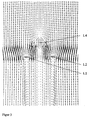
- the sensors 1.1, 1.2 are in the same flow plane, so they do not influence each other and have the same signals with the same flow and the same probe length.
- Influencing by the speed measuring device 6 is also excluded, since it is ensured was that the dust sensors 1.1, 1.2 are to the left and right of the respective trailing area. In this connection, reference is made to FIG. 5.
- the zero point sensor 1.3 lies behind the speed measuring device. Since he is not the flow counteracting surface affects the wake flow of the speed measuring device 6 the zero point signal is not. So there is only electrical contact with the gas flow, a triboelectric Signal caused by impacting particles is excluded.
- the zero point sensor 1.3 is identical to the dust sensors in connection and installation.
- the length of the dust sensors 1.1, 1.2 can be adapted to the respective place of use. About the The length of the sensors can be adapted to the surface that is optimal for the measuring task. in the in general, the sensors 1.1, 1.2 with the same length are approximately in the diameter of the tube manufactured.
- the profile of a dust sensor 1.1 or 1.2 is shown in Figure 4.
- the sensor cleans itself due to the construction. This cleaning effect can be attributed to the eddies occurring at the edges, which sweep away the dust particles and thus prevent dirt from depositing on the probe surface.
- the eddies of the trapezoidal sensor are formed immediately behind the profile. They therefore have a higher energy near the sensor and thus prevent contamination of the surface.
- FIG. 6 shows the block diagram of the electronic circuit for a triboelectric sensor 1.1 or 1.2 or the zero point sensor 1.3.
- the triboelectric sensor signal is transmitted via a shielded cable 3 into the probe head to an activation of the zero point controlled by the microcontroller 4.1 7.1 headed.
- the sensor signal for zero point adjustment is electronically generated by the circuit separated and a zero point signal applied.
- the Signal level through a current-voltage converter with T-feedback network 7.2.
- Isolation amplifier 7.3 the signal is galvanically separated from the subsequent processing.
- Another amplifier 7.4 acts as a line driver, with an additional signal increase to exclude physical transmission errors in the connection cable to the evaluation unit.
- the evaluation unit there is first a line adaptation and first interference signal suppression 7.5.
- the signal is then corrected by an offset determined when the zero point is adjusted 7.6.
- the signal is further increased in amplifier 7.7.
- By periodically switching the A reference comparison is carried out in 7.8 generated reference signal.
- the noise component of the dust signal suppressed by a low-pass filter 7.9.
- the micro controller 4.1 controlled switch 7.10 can be selected between four measuring ranges. Because on the sensor the signal is caused by negative or positive currents caused by the dust particles rectified in a precision rectifier 7.11.
- the signal is in an integration stage 7.12 smoothed and adapted for processing in controller 4.1 by a further amplifier 7.13.
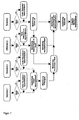
- the dust content is calculated according to FIG. 7.
- the signals of the dust content, differential pressure and temperature are first checked for correctness. This means that the following is checked: Is the signal within the measuring range? Has the signal, unlike the other signals experienced a sudden change? etc. A zero and reference point adjustment is carried out at regular intervals. The evaluation of the error and maintenance status is suspended for this time.
- the signal is OK, it is released for calculation. If an error has occurred, it will Signal replaced by a mean value until the error is corrected or no longer occurs, here the error message remains.
- the dust content is formed from the four sensor signals.
- a weighted mean is formed from the two dust signals according to equation 1, which Constants a and b are dependent on e.g. of the probe length and that in the channel prevailing flow regime.
- the speed is measured using the Differential pressure calculated according to equation 3.
- the tiboelectric signal is of a variety dependent on factors. So played the type of dust (grain size, grain shape and electrical properties) and the procedural boundary conditions (Speed, temperature and gas composition) play a major role.
- the dust content in the operating state can thus be calculated according to equation 4.
- the Constants a, b and c of this equation have to be calibrated by the measuring device being found.
- the Dust concentration For the output to a data acquisition system, the Dust concentration generally given in the normal state. The conversion is done with the gas temperature, the pressure in the duct and the gas moisture according to the calculation specification in VDI / VDE 2040.
Landscapes
- Chemical & Material Sciences (AREA)
- Life Sciences & Earth Sciences (AREA)
- Health & Medical Sciences (AREA)
- Pathology (AREA)
- General Physics & Mathematics (AREA)
- Physics & Mathematics (AREA)
- Immunology (AREA)
- Analytical Chemistry (AREA)
- Biochemistry (AREA)
- General Health & Medical Sciences (AREA)
- Molecular Biology (AREA)
- Biomedical Technology (AREA)
- Engineering & Computer Science (AREA)
- Chemical Kinetics & Catalysis (AREA)
- Electrochemistry (AREA)
- Dispersion Chemistry (AREA)
- Sampling And Sample Adjustment (AREA)
Applications Claiming Priority (2)
| Application Number | Priority Date | Filing Date | Title |
|---|---|---|---|
| DE19729144 | 1997-07-08 | ||
| DE1997129144 DE19729144C2 (de) | 1997-07-08 | 1997-07-08 | Verfahren und Gerätesystem zur kontinuierlichen Ermittlung der Staubkonzentration in strömenden Gasen |
Publications (2)
| Publication Number | Publication Date |
|---|---|
| EP0890834A2 true EP0890834A2 (fr) | 1999-01-13 |
| EP0890834A3 EP0890834A3 (fr) | 2000-07-26 |
Family
ID=7835016
Family Applications (1)
| Application Number | Title | Priority Date | Filing Date |
|---|---|---|---|
| EP98112433A Withdrawn EP0890834A3 (fr) | 1997-07-08 | 1998-07-04 | Procédé et appareil pour la détermination en continu de la teneur en poussière des gaz en écoulement |
Country Status (2)
| Country | Link |
|---|---|
| EP (1) | EP0890834A3 (fr) |
| DE (1) | DE19729144C2 (fr) |
Cited By (5)
| Publication number | Priority date | Publication date | Assignee | Title |
|---|---|---|---|---|
| DE19900484A1 (de) * | 1999-01-08 | 2000-08-10 | Wap Reinigungssysteme | Meßsystem zur Reststaubüberwachung für Sicherheitssauger |
| WO2008008169A3 (fr) * | 2006-07-07 | 2008-04-03 | Univation Tech Llc | SystÈmes et mÉthodes de dÉtection des impuretÉs dans les systÈmes de rÉacteurs |
| CN104502161A (zh) * | 2014-12-31 | 2015-04-08 | 郑州光力科技股份有限公司 | 粉尘采样器检定装置 |
| CN107247017A (zh) * | 2017-08-15 | 2017-10-13 | 嘉兴华涛仪器仪表有限责任公司 | 一种粉尘测量传感器 |
| CN112986085A (zh) * | 2021-04-09 | 2021-06-18 | 西安热工研究院有限公司 | 一种火电厂静电法粉尘浓度测量装置 |
Families Citing this family (6)
| Publication number | Priority date | Publication date | Assignee | Title |
|---|---|---|---|---|
| DE10121620B4 (de) | 2000-05-02 | 2008-08-21 | Dr. Födisch Umweltmeßtechnik GmbH | Verfahren und Einrichtung zur extraktiven triboelektrischen Staub- und Aerosolmessung in strömenden Gasen |
| DE10022391C2 (de) * | 2000-05-02 | 2002-03-07 | Foedisch Umweltmestechnik Gmbh | Verfahren und Einrichtung zur extraktiven triboelektrischen Staubmessung in strömenden Gasen |
| DE102004010661B4 (de) * | 2004-02-26 | 2006-06-14 | Fachhochschule Jena | Verfahren und Vorrichtung zur kontinuierlichen Messung der Staubkonzentration in strömenden Gasen |
| DE102008056938B4 (de) * | 2008-08-22 | 2014-01-02 | Oliver Frieters | Entstaubungsanlage mit Luft-Rückführung und Reststaubmessung sowie Steuerungsverfahren hierfür |
| DE102009009839A1 (de) * | 2009-01-22 | 2010-07-29 | Tesona Gmbh & Co. Kg | Multifunktionale Sensoranordnung |
| DE202009001936U1 (de) | 2009-03-04 | 2009-05-20 | Höcker Polytechnik GmbH | Partikelstromwächter |
Family Cites Families (15)
| Publication number | Priority date | Publication date | Assignee | Title |
|---|---|---|---|---|
| US3794909A (en) * | 1971-12-08 | 1974-02-26 | Ikor Inc | Apparatus for and method of sensing particulate matter |
| DE2163045C3 (de) * | 1971-12-18 | 1974-05-30 | Daimler-Benz Ag, 7000 Stuttgart | Kombinationssonde |
| HU180259B (en) * | 1978-03-28 | 1983-02-28 | Mta Mueszaki Kemiai Kutato Int | Process for the continuous measuring of the alteration in the grain size of substances in powder phase |
| GB2085597B (en) * | 1980-10-17 | 1985-01-30 | Redland Automation Ltd | Method and apparatus for detemining the mass flow of a fluid |
| DD209089A3 (de) * | 1981-07-17 | 1984-04-18 | Horst Kretschmer | Messverfahren zur ermittlung des massenstromes staubfoermiger und feinkoerniger brennstoffe |
| DD201507B1 (de) * | 1981-07-17 | 1991-03-28 | Manfred Schingnitz | Verfahren zur ermittlung des massenstromes feinkoerniger materialien |
| JPS59202043A (ja) * | 1983-04-30 | 1984-11-15 | Horiba Ltd | デイ−ゼル排気ガス中の煤粒子測定装置 |
| US4607228A (en) * | 1984-01-13 | 1986-08-19 | Battelle Development Corporation | Apparatus and method for measuring the concentration of solid particles in a fluid stream |
| US4631482A (en) * | 1984-10-09 | 1986-12-23 | Auburn International, Inc. | Dust flow inducing monitor |
| GB2266772B (en) * | 1992-04-30 | 1995-10-25 | Pollution Control & Measuremen | Detecting particles in a gas flow |
| GB2277154B (en) * | 1993-04-06 | 1997-06-25 | Pollution Control & Measuremen | Method and apparatus for detecting particles in a flow |
| US5448172A (en) * | 1993-05-05 | 1995-09-05 | Auburn International, Inc. | Triboelectric instrument with DC drift compensation |
| DE19529544C2 (de) * | 1995-08-11 | 1998-12-10 | Kessler & Luch Gmbh | Anordnung zum Messen von Volumenströmen von insbesondere mit Verunreinigungen beladener Luft und anderer Gase |
| US5644241A (en) * | 1995-09-25 | 1997-07-01 | Bindicator Company | Measurement of solid particle concentration in a fluid stream responsive to magnitude and rate of change of a triboelectric probe output signal |
| FR2771174B1 (fr) * | 1997-11-17 | 2000-01-14 | Cgia | Procede, dispositif et installation pour l'analyse d'un effluent gazeux avec determination d'un taux de poussieres |
-
1997
- 1997-07-08 DE DE1997129144 patent/DE19729144C2/de not_active Expired - Fee Related
-
1998
- 1998-07-04 EP EP98112433A patent/EP0890834A3/fr not_active Withdrawn
Cited By (7)
| Publication number | Priority date | Publication date | Assignee | Title |
|---|---|---|---|---|
| DE19900484A1 (de) * | 1999-01-08 | 2000-08-10 | Wap Reinigungssysteme | Meßsystem zur Reststaubüberwachung für Sicherheitssauger |
| US6779380B1 (en) | 1999-01-08 | 2004-08-24 | Wap Reinigungssysteme Gmbh & Co. | Measuring system for the control of residual dust in safety vacuum cleaners |
| WO2008008169A3 (fr) * | 2006-07-07 | 2008-04-03 | Univation Tech Llc | SystÈmes et mÉthodes de dÉtection des impuretÉs dans les systÈmes de rÉacteurs |
| CN104502161A (zh) * | 2014-12-31 | 2015-04-08 | 郑州光力科技股份有限公司 | 粉尘采样器检定装置 |
| CN104502161B (zh) * | 2014-12-31 | 2017-07-07 | 郑州光力科技股份有限公司 | 粉尘采样器检定装置 |
| CN107247017A (zh) * | 2017-08-15 | 2017-10-13 | 嘉兴华涛仪器仪表有限责任公司 | 一种粉尘测量传感器 |
| CN112986085A (zh) * | 2021-04-09 | 2021-06-18 | 西安热工研究院有限公司 | 一种火电厂静电法粉尘浓度测量装置 |
Also Published As
| Publication number | Publication date |
|---|---|
| EP0890834A3 (fr) | 2000-07-26 |
| DE19729144C2 (de) | 2001-02-22 |
| DE19729144A1 (de) | 1999-02-04 |
Similar Documents
| Publication | Publication Date | Title |
|---|---|---|
| DE19729144C2 (de) | Verfahren und Gerätesystem zur kontinuierlichen Ermittlung der Staubkonzentration in strömenden Gasen | |
| EP3327406B1 (fr) | Procédé de fonctionnement d'un débitmètre massique à accélération de coriolis et débitmètre massique à accélération de coriolis | |
| EP2936082B1 (fr) | Débitmètre a vortex et procédé de mesure du taux de vide d'un écoulement multiphasique | |
| DE60213258T2 (de) | Diagnose fuer piezoelektrischen sensor | |
| EP0386665A2 (fr) | Procédé et appareil pour mesurer des particules dans des systèmes polydispersés et pour mesurer la concentration de particules d'aérosols monodispersés | |
| EP2601489A1 (fr) | Débitmètre à effet coriolis et procédé servant à faire fonctionner un débitmètre à effet coriolis | |
| EP3926309A1 (fr) | Procédé de traitement du signal pour peseuses multi-têtes | |
| AT505522B1 (de) | Vorrichtung zum bestimmen von strömungsparametern einer partikel - fluidum - strömung | |
| EP2847555B1 (fr) | Procédé de surveillance de l'état de fonctionnement d'un transducteur d'ultrasons dans un appareil de mesure de débit à ultrasons | |
| DE102009007126A1 (de) | Verfahren und Vorrichtung zur Messung der Rußbeladung in Abgassystemen von Dieselmotoren | |
| DE4101739C2 (de) | Luftaufbereitungsanlage | |
| DE10224294A1 (de) | Verfahren zur Ultraschall-Laufzeit-Mengenmessung | |
| EP1910814A2 (fr) | Procede de verification non destructive de tuyaux, pour detecter d'eventuels defauts superficiels | |
| DE102010030952A1 (de) | Vorrichtung zur Bestimmung und/oder Überwachung eines Volumendurchflusses und/oder eienr Durchflussgeschwindigkeit | |
| DE2919230A1 (de) | Messverfahren und messchaltung zur kontinuierlichen feuchtemessung | |
| DE102005063352A1 (de) | Verfahren zur zerstörungsfreien Prüfung von Rohren auf Oberflächenfehler | |
| DE102010042993A1 (de) | Sammler, Gerät, Verfahren und Programm für das Messen einer Sammelmenge | |
| DE102004010661B4 (de) | Verfahren und Vorrichtung zur kontinuierlichen Messung der Staubkonzentration in strömenden Gasen | |
| DE102018220600B4 (de) | Verfahren und Vorrichtung zum Detektieren von Partikeln | |
| EP3940342B1 (fr) | Appareil de mesure | |
| EP4428500B1 (fr) | Procédé de fonctionnement d'un débitmètre à induction magnétique et débitmètre à induction magnétique | |
| DE102004056370A1 (de) | Mess- und Betriebsschaltung für Coriolismassedurchflussaufnehmer | |
| DE102019130139A1 (de) | Lüfter-Filter-Einheit und Verfahren zur Bestimmung eines Verschmutzungsgrades des Filterelements der Lüfter-Filter-Einheit | |
| DE2713622A1 (de) | Verfahren und vorrichtung zur staubueberwachung | |
| EP1659393B1 (fr) | Analyseur de gaz à infrarouge non dispersif selon le principe du double faisceau |
Legal Events
| Date | Code | Title | Description |
|---|---|---|---|
| PUAI | Public reference made under article 153(3) epc to a published international application that has entered the european phase |
Free format text: ORIGINAL CODE: 0009012 |
|
| AK | Designated contracting states |
Kind code of ref document: A2 Designated state(s): AT BE ES FI FR GB IT NL SE |
|
| AX | Request for extension of the european patent |
Free format text: AL;LT;LV;MK;RO;SI |
|
| PUAL | Search report despatched |
Free format text: ORIGINAL CODE: 0009013 |
|
| AK | Designated contracting states |
Kind code of ref document: A3 Designated state(s): AT BE CH CY DE DK ES FI FR GB GR IE IT LI LU MC NL PT SE |
|
| AX | Request for extension of the european patent |
Free format text: AL;LT;LV;MK;RO;SI |
|
| 17P | Request for examination filed |
Effective date: 20000918 |
|
| AKX | Designation fees paid |
Free format text: AT BE ES FI FR GB IT NL SE |
|
| 17Q | First examination report despatched |
Effective date: 20030912 |
|
| REG | Reference to a national code |
Ref country code: DE Ref legal event code: 8566 |
|
| STAA | Information on the status of an ep patent application or granted ep patent |
Free format text: STATUS: THE APPLICATION IS DEEMED TO BE WITHDRAWN |
|
| 18D | Application deemed to be withdrawn |
Effective date: 20040203 |