EP3327406B1 - Procédé de fonctionnement d'un débitmètre massique à accélération de coriolis et débitmètre massique à accélération de coriolis - Google Patents
Procédé de fonctionnement d'un débitmètre massique à accélération de coriolis et débitmètre massique à accélération de coriolis Download PDFInfo
- Publication number
- EP3327406B1 EP3327406B1 EP17198025.3A EP17198025A EP3327406B1 EP 3327406 B1 EP3327406 B1 EP 3327406B1 EP 17198025 A EP17198025 A EP 17198025A EP 3327406 B1 EP3327406 B1 EP 3327406B1
- Authority
- EP
- European Patent Office
- Prior art keywords
- frequency
- oscillation
- amplitude
- signal
- measurement signal
- Prior art date
- Legal status (The legal status is an assumption and is not a legal conclusion. Google has not performed a legal analysis and makes no representation as to the accuracy of the status listed.)
- Active
Links
Images

Classifications
-
- G—PHYSICS
- G01—MEASURING; TESTING
- G01F—MEASURING VOLUME, VOLUME FLOW, MASS FLOW OR LIQUID LEVEL; METERING BY VOLUME
- G01F1/00—Measuring the volume flow or mass flow of fluid or fluent solid material wherein the fluid passes through a meter in a continuous flow
- G01F1/76—Devices for measuring mass flow of a fluid or a fluent solid material
- G01F1/78—Direct mass flowmeters
- G01F1/80—Direct mass flowmeters operating by measuring pressure, force, momentum, or frequency of a fluid flow to which a rotational movement has been imparted
- G01F1/84—Coriolis or gyroscopic mass flowmeters
- G01F1/8409—Coriolis or gyroscopic mass flowmeters constructional details
- G01F1/8436—Coriolis or gyroscopic mass flowmeters constructional details signal processing
-
- G—PHYSICS
- G01—MEASURING; TESTING
- G01F—MEASURING VOLUME, VOLUME FLOW, MASS FLOW OR LIQUID LEVEL; METERING BY VOLUME
- G01F25/00—Testing or calibration of apparatus for measuring volume, volume flow or liquid level or for metering by volume
- G01F25/10—Testing or calibration of apparatus for measuring volume, volume flow or liquid level or for metering by volume of flowmeters
-
- G—PHYSICS
- G01—MEASURING; TESTING
- G01F—MEASURING VOLUME, VOLUME FLOW, MASS FLOW OR LIQUID LEVEL; METERING BY VOLUME
- G01F1/00—Measuring the volume flow or mass flow of fluid or fluent solid material wherein the fluid passes through a meter in a continuous flow
- G01F1/76—Devices for measuring mass flow of a fluid or a fluent solid material
- G01F1/78—Direct mass flowmeters
- G01F1/80—Direct mass flowmeters operating by measuring pressure, force, momentum, or frequency of a fluid flow to which a rotational movement has been imparted
- G01F1/84—Coriolis or gyroscopic mass flowmeters
-
- G—PHYSICS
- G01—MEASURING; TESTING
- G01F—MEASURING VOLUME, VOLUME FLOW, MASS FLOW OR LIQUID LEVEL; METERING BY VOLUME
- G01F1/00—Measuring the volume flow or mass flow of fluid or fluent solid material wherein the fluid passes through a meter in a continuous flow
- G01F1/76—Devices for measuring mass flow of a fluid or a fluent solid material
- G01F1/78—Direct mass flowmeters
- G01F1/80—Direct mass flowmeters operating by measuring pressure, force, momentum, or frequency of a fluid flow to which a rotational movement has been imparted
- G01F1/84—Coriolis or gyroscopic mass flowmeters
- G01F1/845—Coriolis or gyroscopic mass flowmeters arrangements of measuring means, e.g., of measuring conduits
- G01F1/8468—Coriolis or gyroscopic mass flowmeters arrangements of measuring means, e.g., of measuring conduits vibrating measuring conduits
-
- G—PHYSICS
- G01—MEASURING; TESTING
- G01F—MEASURING VOLUME, VOLUME FLOW, MASS FLOW OR LIQUID LEVEL; METERING BY VOLUME
- G01F25/00—Testing or calibration of apparatus for measuring volume, volume flow or liquid level or for metering by volume
-
- G—PHYSICS
- G01—MEASURING; TESTING
- G01D—MEASURING NOT SPECIALLY ADAPTED FOR A SPECIFIC VARIABLE; ARRANGEMENTS FOR MEASURING TWO OR MORE VARIABLES NOT COVERED IN A SINGLE OTHER SUBCLASS; TARIFF METERING APPARATUS; MEASURING OR TESTING NOT OTHERWISE PROVIDED FOR
- G01D7/00—Indicating measured values
-
- G—PHYSICS
- G01—MEASURING; TESTING
- G01F—MEASURING VOLUME, VOLUME FLOW, MASS FLOW OR LIQUID LEVEL; METERING BY VOLUME
- G01F1/00—Measuring the volume flow or mass flow of fluid or fluent solid material wherein the fluid passes through a meter in a continuous flow
- G01F1/76—Devices for measuring mass flow of a fluid or a fluent solid material
- G01F1/78—Direct mass flowmeters
- G01F1/80—Direct mass flowmeters operating by measuring pressure, force, momentum, or frequency of a fluid flow to which a rotational movement has been imparted
- G01F1/84—Coriolis or gyroscopic mass flowmeters
- G01F1/845—Coriolis or gyroscopic mass flowmeters arrangements of measuring means, e.g., of measuring conduits
- G01F1/8468—Coriolis or gyroscopic mass flowmeters arrangements of measuring means, e.g., of measuring conduits vibrating measuring conduits
- G01F1/849—Coriolis or gyroscopic mass flowmeters arrangements of measuring means, e.g., of measuring conduits vibrating measuring conduits having straight measuring conduits
Definitions
- the invention is based on a method for operating a Coriolis mass flow measuring device, the Coriolis mass flow measuring device having at least one measuring tube, at least one vibration generator, at least two vibration sensors and at least one control and evaluation unit, the vibration generator and the vibration sensors being arranged on the measuring tube , wherein the measuring tube can be flowed through by a medium, wherein the vibration generator sets the measuring tube into a harmonic oscillation with the excitation frequency f 0 and the excitation amplitude A 0 , the first and the second vibration sensor detecting the vibration of the measuring tube, the first vibration sensor recording the vibration forwards the first measurement signal to the control and evaluation unit and the second vibration sensor forwards the vibration as the second measurement signal to the control and evaluation unit and for the first measurement signal and / or the second measurement signal l at least one comparison measurement signal is determined.
- the invention is based on a Coriolis mass flow meter with at least one measuring tube, at least one vibration generator, at least two vibration sensors and at least one control and evaluation unit, the vibration generator and the vibration sensors being arranged on the measuring tube, the vibration generator being designed in such a way that he puts the measuring tube into a harmonic oscillation with the excitation frequency f 0 and the excitation amplitude A 0 during operation, the first and the second oscillation sensors being designed such that they detect the oscillation of the measuring tube during operation, the first oscillation sensor being the oscillation as forwards the first measurement signal to the control and evaluation unit and wherein the second vibration sensor forwards the vibration as a second measurement signal to the control and evaluation unit and wherein at least one comparison is made from the first measurement signal and / or the second measurement signal measurement signal is determined.
- both the excitation frequency and the frequency at which the phase difference between the input and output signals is determined correspond to the basic resonance frequency of the measuring tube in a movement mode.
- the measuring tube is often excited to vibrate by the vibration generator in an excitation mode (central antinode between the inlet and outlet-side nodes of the measuring tube), the influence of the Coriolis force causing a superimposed vibration of the measuring tube in the next higher vibration mode of the measuring tube (additional central zero point of vibration of the measuring tube ). These movements are of course superimposed on one another.
- the measured signal can be passed, for example, through a bandpass filter which is essentially transparent to the fundamental frequency of one of the excited oscillation modes, that is to say, for example, to the excitation frequency or the fundamental resonance frequency of higher oscillation modes.
- the DC voltage component can also be determined and taken into account in the signal evaluation, for example in order to detect insulation faults.
- the publication DE 10 2008 059 920 A1 discloses a method for identifying system-describing parameters, which can be carried out during operation in a closed control loop. For this purpose, a setpoint, such as the phase between the excitation signal and the measurement signal, is varied. The variation selectively determines at least one parameter of the excited natural shape, which has an effect on the recorded measurement signal, of the measuring tube.
- the publication DE 10 2011 086 395 A1 discloses a method for monitoring the vibration properties in a Coriolis mass flow meter, in particular to detect changes due to abrasion, corrosion or coating of the measuring tube.
- a vibration system is simulated using a digital model that has at least one adjustable parameter.
- the signal for excitation of the vibration has short-term signal modulations, the effects of these short-term signal modulations on the vibration system and on the digital model being recorded. It also examines whether the adjustable parameter exceeds a limit.
- non-linear disturbances occur, for example, when the vibration generator and / or the vibration sensors are poorly aligned or when the vibration generator and / or the vibration sensors have mechanically detached.
- non-linear disturbances occur if the measuring tube geometry deviates from the target geometry, for example as a result of overheating or as a result of a fall.
- the invention is based on the object of specifying a method for operating a Coriolis mass flow meter, with which in particular nonlinear disturbances can be detected.
- the invention is based on the object of specifying a corresponding Coriolis mass flow meter.
- the aforementioned object is achieved in that, based on the excitation frequency f 0 and the excitation amplitude A 0, an expected value of the amplitude and / or the phase and / or at least one of the variables derived therefrom is determined with at least one evaluation frequency, the Evaluation frequency corresponds to the excitation frequency f 0 and / or at least one harmonic harmonic of the excitation frequency f 0 , that the amplitude and / or the phase and / or the magnitude of the comparison measurement signal derived therefrom is recorded exclusively at the evaluation frequency, that the expected value of the amplitude and / or the phase and / or the quantity derived therefrom is compared with the corresponding value of the comparison measurement signal and a measure for the deviation is determined and that a message is output when the deviation of the expected value with the corresponding value of the comparison measurement signal exceeds an upper limit value or falls below a lower limit value.
- the fact is used that nonlinear disturbances of a harmonically excited linear system lead to nonlinear reaction signals, that is to say they do not or not only have an effect on the amplitude and / or the phase of the vibration measured in the linear case; they produce further signal components, such as higher noise or signals with different frequencies in the comparison measurement signal.
- the method according to the invention is based on a comparison of the expected values of the relevant variables with the actually measured values of the corresponding variables.
- the relevant variables mentioned above are preferably those variables by means of which a non-linearity of the comparison measurement signal can be made measurable.
- the comparison measurement signal is particularly preferably measured not only in the range of the excitation frequency f 0 , but also is examined for the presence of further frequency components in the range of the harmonic harmonics of the excitation frequency f 0 .
- This embodiment differs from the obvious, but very complex solution of the analysis of the comparison measurement signal by means of a Fourier analysis in that an analysis of the comparison measurement signal exclusively in well-defined frequency ranges, namely in the range around the excitation frequency f 0 and in the range around harmonic harmonics of the excitation frequency f 0 around. In contrast to a Fourier analysis, this analysis at defined frequency ranges is particularly simple, while at the same time a high resolution can be guaranteed.
- the comparison measurement signal in the area of the excitation frequency f 0 and / or in the area of the harmonic harmonic can be evaluated, for example, by the comparison measurement signal being a bandpass filter, which is essentially transparent to the excitation frequency f 0 or to the frequency of a harmonic of interest, is filtered.
- the term “in the range” is understood to mean a frequency range which extends up to ⁇ 10% or ⁇ 5% or ⁇ 1% of the evaluation frequency around the evaluation frequency.
- signal processing processes such as the filtering of the comparison measurement signal by a bandpass filter, are always subject to technical inaccuracies, which result in a certain blurring of the frequency to be filtered.
- the state of the measuring system that is to say the state of the Coriolis mass flow meter
- the state of the measuring system can be monitored particularly easily by the method according to the invention, and faults can be detected particularly easily.
- the excitation frequency f 0 corresponds to a resonance frequency of the measuring tube.
- the expected value of the amplitude and / or the phase and / or the quantity derived therefrom can be determined anew with each measurement or can be determined before a measurement process, for example as part of a calibration, or can be determined when the Coriolis mass flow meter is started up.
- the at least one variable derived from the amplitude is the power and / or a value for the harmonic distortion (THD value) and / or a value for the harmonic distortion including the noise (THD + N value) and / or the distortion factor and / or the signal-to-noise ratio (SNR).
- the THD value is a measure of harmonic distortion of the comparison measurement signal.
- the signal powers are therefore both on the excitation frequency f 0 and on at least one harmonic Harmonic of the excitation frequency f 0 is determined and then related to one another in accordance with the above relationship.
- the expected value of the THD value and the THD value of the comparison measurement signal are then related to one another in order to determine the deviation of the THD values.
- the ratio of the power P 0 to the total power of the comparison measurement signal P tot can also be formed.
- the amplitude ratios can be related to one another in accordance with the relationships described above and referred to as THD values.
- the harmonic distortion is also a measure of the nonlinear distortion of a harmonic signal.
- the harmonic distortion indicates the proportion of harmonic harmonics in the overall signal.
- the harmonic distortion relates to the effective values of the amplitudes.
- the comparison measurement signal is the first measurement signal or the second measurement signal or a sum signal from the first measurement signal and the second measurement signal or a difference signal from the first and the second measurement signal or a further functional relationship between the first and the second Measurement signal.
- the Coriolis mass flow meter has more than two vibration sensors, i.e. three or four or five vibration sensors, which are arranged on a measuring tube and which transmit the vibration to the control as a third or fourth or fifth measurement signal - Forward and evaluation unit, and when the comparison signal is determined from the first and / or the second and / or the third and / or the fourth and / or the fifth measurement signal.
- the Coriolis mass flow measuring device has at least two measuring tubes, at least two vibration generators and at least four vibration sensors, one vibration generator and two vibration sensors each being arranged on one measuring tube and, during operation, the respective measuring tube in a harmonic vibration with the excitation frequency f 0 and the excitation amplitude A 0 , with the first and second vibration sensors detecting the vibration of the measuring tube assigned to the vibration sensors, with the first vibration sensor transmitting the vibration as the first measurement signal to the control and evaluation unit, and with the second vibration sensor with the vibration as the second Forwards the measurement signal to the control and evaluation unit, the third vibration sensor forwards the vibration of the measuring tube as a third measurement signal to the control and evaluation unit, the fourth vibration sensor d
- the vibration of the measuring tube is forwarded to the control and evaluation unit as a fourth measurement signal and at least one comparison measurement signal is determined from the first measurement signal and / or the second measurement signal and / or the third measurement signal and / or the fourth measurement signal, and this comparison signal according to the invention Method is
- This embodiment has the advantage that not only interference components in the range of the excitation frequency and in the range of the harmonic harmonics of the excitation frequency can be detected, but also interference components that have frequencies that are close to the excitation frequency and / or the harmonic harmonics, at the same time the simplicity of the method, that is, the omission of a complete Fourier transformation of the comparison measurement signal, is retained.
- the expected value of the amplitude and / or the phase and / or the quantity derived therefrom and the comparison with the corresponding value of the comparison measurement signal is carried out periodically or it is triggered manually.
- Periodic monitoring can reliably detect changes occurring over time, such as, for example, mechanical detachment of the vibration sensors or misalignment of the vibration generator and / or the vibration sensors.
- the method according to the invention can also be triggered manually on suspicion.
- the Coriolis mass flow meter has a display unit, it is particularly advantageous if the message, in which the deviation between the expected value and the corresponding value of the comparison measurement signal exceeds an upper limit value or falls below a lower limit value, over the Display unit is output. Then the message is immediately perceptible to the user and the user can take appropriate measures to remedy the cause.
- the individual interference signals preferably each having a cause assigned.
- the amplitude and / or the phase and / or the quantity derived therefrom are compared with the values of the interference signals and if the amplitude and / or the phase and / or the quantity of the comparison measurement signal derived therefrom are compared with the corresponding values of the Interference signals essentially match, a second message is output, in which a possible cause of the fault is specified.
- This embodiment is particularly advantageous since, in addition to the information that there is a malfunction, the user is also informed of the possible cause of the malfunction.
- the storage of the interference signals can occur in that comparison measurement signals which have a disturbance, i.e. in which the deviation of the expected value and the corresponding value of the comparison measurement signal exceeds an upper limit value or falls below a lower limit value, the cause of the fault being identified by the user , together with the cause are stored in the control and evaluation unit.
- the object set out at the outset is achieved by a Coriolis mass flow measuring device mentioned at the outset in that the control and evaluation unit is designed in such a way that in operation, starting from the excitation frequency f 0 and the excitation amplitude A 0, at least one evaluation frequency occurs Expected value of the amplitude and / or the phase and / or at least one variable derived therefrom is determined, the evaluation frequency corresponding to the excitation frequency f 0 and / or at least one harmonic harmonic to the excitation frequency f 0 , that the amplitude and / or the phase and / or the magnitude of the comparison measurement signal derived therefrom is recorded exclusively at the evaluation frequency, that the expected value of the amplitude and / or the phase and / or the quantity derived therefrom is compared with the corresponding value of the comparison measurement signal and a measure for the deviation is determined and that a message is output when the deviation of the expected value with the corresponding value of the comparison measurement signal exceeds an upper limit value or
- the Coriolis mass flow meter is particularly preferably designed in such a way that it carries out one of the previously described methods during operation.
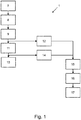
- a first embodiment of a method 1 for operating a Coriolis mass flow meter 2 which is shown, for example, in FIG Fig. 3 is shown.
- the Coriolis mass flow meter 2 has at least one measuring tube 3, at least one vibration generator 4, at least two vibration sensors 5 and at least one control and evaluation unit 6, wherein the vibration generator 4 and the vibration sensors 5 are arranged on the measuring tube 3, the measuring tube 3 from is flowed through a medium.
- the oscillation generator 4 sets the measuring tube 3 in a harmonic oscillation with the excitation frequency f 0 and the excitation amplitude A 0 . It should be noted that the measuring tube 3 vibrates during the entire method 1, and in this respect the step of the excitation 7 continues during the method 1.
- the first and second vibration sensors 5 detect the vibration of the measuring tube 3 and the first vibration sensor 5 passes the vibration as the first measurement signal to the control and evaluation unit 6 and the second vibration sensor 5 passes the vibration to the second measurement signal Control and evaluation unit 6 further.
- a comparison measurement signal 10 is then determined in a further step 9 from the first measurement signal and the second measurement signal.
- the comparison measurement signal 10 corresponds to the first measurement signal.
- the amplitude and the phase of the comparison measurement signal 10 are determined at the excitation frequency f 0 .
- the total power P tot of the comparison measurement signal 10 is determined 12.
- the mass flow rate of the medium flowing through the measuring tube 3 is determined from the measured amplitude and phase and from the comparison with the second measurement signal.
- the power P 0 of the comparison measurement signal 10 is determined from the amplitude at the excitation frequency f 0
- the THD + N value of the comparison measurement signal 10 is determined from the total power P tot and the power P 0 of the comparison measurement signal 10 at the excitation frequency f 0 .
- the THD + N value is compared with a stored expected value and the deviation between the THD + N value and the expected value is determined 16 by forming the difference.
- a warning message is output in a next step 17.
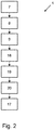
- Fig. 2 shows a second embodiment of a method 1 for operating a Coriolis mass flow meter 2, as described for example above and in Fig. 3 is shown.
- the measuring tube 3 is excited in harmonic oscillation with the excitation frequency f 0 and the amplitude A 0 .
- the vibration sensors 5 record the vibration and pass it on as the first and second measurement signal to the control and evaluation unit 6.
- the comparison measurement signal 10 is then determined 9, which corresponds to the first measurement signal in the exemplary embodiment shown.
- an expected value for the THD value that is to say the ratio of the powers P h to P 0 .
- the THD value of the comparison measurement signal 10 is determined.
- the amplitude of the comparison measurement signal is determined on the excitation frequency f 0 and on the second and third harmonic and the THD value is calculated from this.
- the THD value of the comparison measurement signal (10) is compared with the expected value of the THD value and a measure of the deviation is determined by forming the difference.
- a warning message is issued if the deviation exceeds an upper limit.
- Fig. 3 shows, as already described, an exemplary embodiment of a Coriolis mass flow meter 2.
- the Coriolis mass flow meter 2 has a display unit 21, via which the warning message is output in the event of an upper limit value being exceeded or a lower limit value being undershot.
Landscapes
- Physics & Mathematics (AREA)
- Fluid Mechanics (AREA)
- General Physics & Mathematics (AREA)
- Engineering & Computer Science (AREA)
- Signal Processing (AREA)
- Measuring Volume Flow (AREA)
Claims (8)
- Procédé (1) de fonctionnement d'un débitmètre massique à effet Coriolis (2), le débitmètre massique à effet Coriolis (2) comprenant au moins un tube de mesure (3), au moins un générateur de vibrations (4), au moins deux capteurs de vibrations (5) et au moins une unité de commande et d'évaluation (6), le générateur de vibrations (4) et les capteurs de vibrations (5) étant disposés au niveau du tube de mesure (3), un fluide pouvant s'écouler à travers le tube de mesure (3), le générateur de vibrations (4) déplaçant le tube de mesure (3) suivant une vibration harmonique ayant la fréquence d'excitation f0 et l'amplitude d'excitation A0 (7), le premier et le deuxième capteur de vibration (5) détectant la vibration du tube de mesure (3) et le premier capteur de vibration (5) transmettant la vibration sous la forme d'un premier signal de mesure à l'unité de commande et d'évaluation (6) et le deuxième capteur de vibrations (5) transmettant (8) la vibration sous la forme d'un deuxième signal de mesure à l'unité de commande et d'évaluation (6) et au moins un signal de mesure de comparaison (10) étant déterminé (9) à partir du premier signal de mesure et/ou du deuxième signal de mesure,
caractérisé en ce que
une valeur attendue de l'amplitude et/ou de la phase et/ou d'au moins une grandeur qui en dérive est déterminée en fonction de la fréquence d'excitation f0 et de l'amplitude d'excitation A0 pour au moins une fréquence d'évaluation (18), la fréquence d'évaluation correspondant à la fréquence d'excitation f0 et/ou au moins à une vibration harmonique de la fréquence d'excitation f0,
l'amplitude et/ou la phase et/ou la grandeur qui en dérive du signal de mesure de comparaison (10) sont détectées exclusivement à la fréquence d'évaluation (11, 14, 15, 19),
la valeur attendue de l'amplitude et/ou de la phase et/ou de la grandeur qui en dérive est comparée à la valeur correspondante du signal de mesure de comparaison (10) et une mesure de l'écart est déterminée (20) et
un message est délivré (17) lorsque l'écart de la valeur attendue avec la valeur correspondante du signal de mesure de comparaison (10) dépasse une valeur limite supérieure ou tombe au-dessous d'une valeur limite inférieure. - Procédé (1) selon la revendication 1, caractérisé en ce que l'au moins une grandeur dérivée de l'amplitude est la puissance et/ou une valeur de la distorsion harmonique (valeur THD) et/ou une valeur de la distorsion harmonique incluant le bruit (valeur THD+N) et/ou le facteur de distorsion et/ou le rapport signal/bruit (SNR).
- Procédé (1) selon la revendication 1 ou 2, caractérisé en ce que le signal de mesure de comparaison (10) est le premier signal de mesure ou le deuxième signal de mesure ou un signal de somme du premier signal de mesure et du deuxième signal de mesure ou un signal de différence du premier et du deuxième signal de mesure ou une autre relation fonctionnelle entre le premier et le deuxième signal de mesure.
- Procédé (1) selon l'une des revendications 1 à 3, caractérisé en ce que plus d'une valeur attendue de l'amplitude et/ou de la phase et/ou de la grandeur qui en dérive sont déterminées et en ce que les valeurs attendues de l'amplitude et/ou de la phase et/ou de la grandeur qui en dérive sont comparées simultanément ou successivement aux valeurs correspondantes du signal de mesure de comparaison (10).
- Procédé (1) selon l'une des revendications 1 à 4, caractérisé en ce qu'au moins une valeur attendue supplémentaire de l'amplitude et/ou de la phase et/ou de la grandeur qui en dérive est déterminée à une fréquence d'évaluation qui se situe dans un intervalle de fréquences autour de la fréquence d'excitation f0, l'intervalle de fréquences s'étendant de ±20 à 50 % de la fréquence d'excitation autour de la fréquence d'excitation f0,et/ou à une fréquence d'évaluation qui se situe dans un intervalle de fréquences autour de la vibration harmonique de la fréquence d'excitation f0, l'intervalle de fréquences s'étendant de ±20 à 50 % de la fréquence de la vibration harmonique autour de la fréquence de la vibration harmonique, et en ce que l'amplitude et/ou la phase et/ou la grandeur qui en dérive du signal de mesure de comparaison (10) sont détectées à la fréquence d'évaluation et comparées au signal attendu correspondant.
- Procédé (1) selon l'une des revendications 1 à 5, caractérisé en ce que la détermination de la valeur attendue de l'amplitude et/ou de la phase et/ou de la grandeur qui en dérive et la comparaison avec la valeur correspondante du signal de mesure de comparaison (10) sont effectuées périodiquement ou déclenchées manuellement.
- Débitmètre massique à effet Coriolis (2) comprenant au moins un tube de mesure (3), au moins un générateur de vibrations (4), au moins deux capteurs de vibrations (5) et au moins une unité de commande et d'évaluation (6), le générateur de vibrations (4) et les capteurs de vibrations (5) étant disposés au niveau du tube de mesure (3), le générateur de vibrations (4) étant conçu de façon à déplacer le tube de mesure (3) suivant une vibration harmonique ayant la fréquence d'excitation f0 et l'amplitude d'excitation A0, les premier et deuxième capteurs de vibration (5) étant conçus de façon à détecter la vibration du tube de mesure (3) pendant le fonctionnement, le premier capteur de vibration (5) transmettant la vibration sous la forme d'un premier signal de mesure à l'unité de commande et d'évaluation (6) et le deuxième capteur de vibration (5) transmettant la vibration sous la forme d'un deuxième signal de mesure à l'unité de commande et d'évaluation (6) et au moins un signal de mesure de comparaison (10) étant déterminé à partir du premier signal de mesure et/ou du second signal de mesure,
caractérisé en ce que
l'unité de commande et d'évaluation (6) est conçue de façon à déterminer une valeur attendue de l'amplitude et/ou de la phase et/ou d'au moins une grandeur qui en dérive en fonctionnement sur la base de la fréquence d'excitation f0 et de l'amplitude d'excitation A0 pour au moins une fréquence d'évaluation, la fréquence d'évaluation correspondant à la fréquence d'excitation f0 et/ou au moins d'une vibration harmonique de la fréquence d'excitation f0,
l'amplitude et/ou la phase et/ou la grandeur qui en dérive du signal de mesure de comparaison (10) sont détectées exclusivement à la fréquence d'évaluation,
la valeur attendue de l'amplitude et/ou de la phase et/ou de la grandeur qui en dérive est comparée à la valeur correspondante du signal de mesure de comparaison (10) et une mesure de l'écart est déterminée et
un message est délivré lorsque l'écart de la valeur attendue avec la valeur correspondante du signal de mesure de comparaison (10) dépasse une valeur limite supérieure ou tombe au-dessous d'une valeur limite inférieure. - Débitmètre massique à effet Coriolis (2) selon la revendication 7, caractérisé en ce que le débitmètre massique à effet Coriolis (2) met en œuvre un procédé (1) selon l'une des revendications 1 à 6 en cours de fonctionnement.
Applications Claiming Priority (1)
| Application Number | Priority Date | Filing Date | Title |
|---|---|---|---|
| DE102016122241.0A DE102016122241A1 (de) | 2016-11-18 | 2016-11-18 | Verfahren zum Betreiben eines Coriolis-Massedurchflussmessgeräts und Coriolis-Massedurchflussmessgerät |
Publications (2)
| Publication Number | Publication Date |
|---|---|
| EP3327406A1 EP3327406A1 (fr) | 2018-05-30 |
| EP3327406B1 true EP3327406B1 (fr) | 2020-06-17 |
Family
ID=60162134
Family Applications (1)
| Application Number | Title | Priority Date | Filing Date |
|---|---|---|---|
| EP17198025.3A Active EP3327406B1 (fr) | 2016-11-18 | 2017-10-24 | Procédé de fonctionnement d'un débitmètre massique à accélération de coriolis et débitmètre massique à accélération de coriolis |
Country Status (4)
| Country | Link |
|---|---|
| US (1) | US10641642B2 (fr) |
| EP (1) | EP3327406B1 (fr) |
| CN (1) | CN108072411B (fr) |
| DE (1) | DE102016122241A1 (fr) |
Families Citing this family (8)
| Publication number | Priority date | Publication date | Assignee | Title |
|---|---|---|---|---|
| DE102018121449A1 (de) * | 2018-09-03 | 2020-03-05 | Krohne Messtechnik Gmbh | Verfahren zur Verifizierung eines Nutzsignalanteils eines periodischen Sensorsignals |
| DE102018123534A1 (de) * | 2018-09-25 | 2020-03-26 | Krohne Messtechnik Gmbh | Verahren zum Ermitteln des Gasanteils in dem ein Coriolis-Massedurchflussmessgerät durchströmenden Medium |
| DE102018132672A1 (de) | 2018-12-18 | 2020-06-18 | Endress+Hauser Flowtec Ag | Vibronischer Messaufnehmer mit mindestens zwei Temperatursensoren |
| CN113242960B (zh) * | 2018-12-20 | 2024-05-14 | 恩德斯+豪斯流量技术股份有限公司 | 科里奥利质量流量计 |
| EP4121724B1 (fr) * | 2020-03-20 | 2024-01-31 | Endress + Hauser Flowtec AG | Procédé d'utilisation d'un dispositif de mesure à effet coriolis |
| DE102020123653A1 (de) * | 2020-09-10 | 2022-03-10 | Krohne Ag | Verfahren zum Betreiben eines Ultraschall-Durchflussmessgeräats und Ultraschall-Durchflussmessgerät |
| DE102021118961A1 (de) * | 2021-07-22 | 2023-01-26 | Endress+Hauser Flowtec Ag | Verfahren zum Betreiben eines Coriolis-Massedurchflussmessgerätes |
| CN115950507B (zh) * | 2022-12-19 | 2026-04-21 | 西安精擘华科技有限公司 | 基于状态观测模型的科氏力传感器驱动控制方法 |
Family Cites Families (22)
| Publication number | Priority date | Publication date | Assignee | Title |
|---|---|---|---|---|
| GB8705758D0 (en) * | 1987-03-11 | 1987-04-15 | Schlumberger Electronics Uk | Mass flow measurement |
| US5734112A (en) * | 1996-08-14 | 1998-03-31 | Micro Motion, Inc. | Method and apparatus for measuring pressure in a coriolis mass flowmeter |
| US20030216874A1 (en) * | 2002-03-29 | 2003-11-20 | Henry Manus P. | Drive techniques for a digital flowmeter |
| US8447534B2 (en) * | 1997-11-26 | 2013-05-21 | Invensys Systems, Inc. | Digital flowmeter |
| US6092409A (en) * | 1998-01-29 | 2000-07-25 | Micro Motion, Inc. | System for validating calibration of a coriolis flowmeter |
| US20060235629A1 (en) * | 2003-05-21 | 2006-10-19 | Walker Jeffrey S | Flow meter monitoring and data logging system |
| DE102004031637A1 (de) * | 2004-06-30 | 2006-01-26 | Abb Patent Gmbh | Verfahren zum Betrieb einer Messeinrichtung, insbesondere einer Durchflussmesseinrichtung |
| CN101421593B (zh) | 2006-02-27 | 2011-11-16 | 微动公司 | 流量计和检测流量计的电缆线路中的电缆故障的方法 |
| DE102006017676B3 (de) * | 2006-04-12 | 2007-09-27 | Krohne Meßtechnik GmbH & Co KG | Verfahren zum Betrieb eines Coriolis-Massendurchflußmeßgeräts |
| US7617055B2 (en) * | 2006-08-28 | 2009-11-10 | Invensys Systems, Inc. | Wet gas measurement |
| EP2257776B1 (fr) * | 2008-02-11 | 2017-08-02 | Micro Motion, Inc. | Procédé pour détecter une perturbation de procédé dans un dispositif d'écoulement vibrant |
| DE102008050116A1 (de) * | 2008-10-06 | 2010-04-08 | Endress + Hauser Flowtec Ag | In-Line-Meßgerät |
| CN102216740B (zh) * | 2008-11-19 | 2013-07-17 | 微动公司 | 具有改进的模式分离的科里奥利流量计 |
| DE102008059920B4 (de) | 2008-12-02 | 2016-07-14 | Krohne Meßtechnik GmbH & Co KG | Verfahren zum Betreiben eines Resonanzmeßsystems und diesbezügliches Resonanzmeßsystem |
| DK2519806T3 (en) * | 2009-12-31 | 2018-05-22 | Flowtec Ag | Measurement system with a vibration type transducer |
| EP2601489A1 (fr) * | 2010-08-02 | 2013-06-12 | Siemens Aktiengesellschaft | Débitmètre à effet coriolis et procédé servant à faire fonctionner un débitmètre à effet coriolis |
| JP5510747B2 (ja) * | 2010-11-05 | 2014-06-04 | 横河電機株式会社 | コリオリ質量流量計 |
| CN102393661B (zh) * | 2011-09-21 | 2013-03-06 | 北京航空航天大学 | 一种科氏质量流量计数字闭环控制系统 |
| DE102011086395A1 (de) | 2011-11-15 | 2013-05-16 | Endress + Hauser Flowtec Ag | Verfahren zum Überwachen der Schwingungseigenschaften in einem Coriolis-Durchflussmessgerät |
| US9689736B2 (en) | 2014-10-31 | 2017-06-27 | Invensys Systems, Inc. | Method to provide a quality measure for meter verification results |
| DE102014016820A1 (de) | 2014-11-14 | 2016-05-19 | Abb Technology Ag | Verfahren zum Betrieb eines Durchflussmessers |
| WO2016107693A1 (fr) * | 2014-12-30 | 2016-07-07 | Endress+Hauser Flowtec Ag | Procédé de mesure de densité d'un fluide |
-
2016
- 2016-11-18 DE DE102016122241.0A patent/DE102016122241A1/de not_active Withdrawn
-
2017
- 2017-10-24 EP EP17198025.3A patent/EP3327406B1/fr active Active
- 2017-11-14 CN CN201711120985.1A patent/CN108072411B/zh active Active
- 2017-11-20 US US15/817,446 patent/US10641642B2/en active Active
Non-Patent Citations (1)
| Title |
|---|
| None * |
Also Published As
| Publication number | Publication date |
|---|---|
| US20180143064A1 (en) | 2018-05-24 |
| CN108072411A (zh) | 2018-05-25 |
| DE102016122241A1 (de) | 2018-05-24 |
| US10641642B2 (en) | 2020-05-05 |
| EP3327406A1 (fr) | 2018-05-30 |
| CN108072411B (zh) | 2020-11-10 |
Similar Documents
| Publication | Publication Date | Title |
|---|---|---|
| EP3327406B1 (fr) | Procédé de fonctionnement d'un débitmètre massique à accélération de coriolis et débitmètre massique à accélération de coriolis | |
| EP4028731B1 (fr) | Procédé pour faire fonctionner un dispositif de mesure avec au moins un oscillateur et dispositif de mesure pour mettre en oeuvre ledit procédé | |
| DE102006017676B3 (de) | Verfahren zum Betrieb eines Coriolis-Massendurchflußmeßgeräts | |
| DE102009002682B4 (de) | Einrichtung und Verfahren zur Residuenauswertung eines Residuums zur Erkennung von Systemfehlern im Systemverhalten eines Systems eines Flugzeugs | |
| EP1537390B1 (fr) | Procede pour saisir des oscillations de la ligne d'arbres d'une machine electrique | |
| EP2936082B1 (fr) | Débitmètre a vortex et procédé de mesure du taux de vide d'un écoulement multiphasique | |
| EP2601489A1 (fr) | Débitmètre à effet coriolis et procédé servant à faire fonctionner un débitmètre à effet coriolis | |
| DE102016108986A1 (de) | Verfahren zur Detektion von Rohrleitungsschwingungen und Messgerät | |
| EP2677284B1 (fr) | Procédé de fonctionnement d'un système de mesure à résonance et système de mesure à résonance correspondant | |
| WO2019086188A2 (fr) | Procédé de détermination de la formation de dépôt dans un tube de mesure et dispositif de mesure pour la mise en œuvre du procédé | |
| EP3273209B1 (fr) | Procédé de fonctionnement d'un débitmètre et débitmètre | |
| DE102020123945B4 (de) | Verfahren zum Betreiben eines magnetisch-induktiven Durchflussmessgeräts und entsprechendes magnetisch-induktives Durchflussmessgerät | |
| DE102019123368A1 (de) | Verfahren und Messgerät zum Bestimmen der Viskosität eines Mediums | |
| EP2936085B1 (fr) | Débitmètre a vortex et procede de mesure de la qualité des procédé et des conditions d'installation | |
| DE102020114713A1 (de) | Verfahren zur Ermittlung von Durchflussmesswerten eines Coriolis- Massedurchflussmessgeräts beim Vorliegen einer Zweiphasenströmung | |
| EP4341649B1 (fr) | Procédé de mesure de débit soumis à une interférence, débitmètre magnéto-inductif et produit-programme informatique | |
| DE102017129036A1 (de) | Verfahren zum Bestimmen der Viskosität eines Mediums mittels eines Coriolis-Massedurchflussmessers und Coriolis- Massedurchflussmesser zur Durchführung des Verfahrens | |
| DE102010015421A1 (de) | Verfahren zum Überprüfen eines Coriolis-Massendurchflussmessgeräts sowie Coriolis-Massendurchflussmessgerät | |
| DE102021120452A1 (de) | Verfahren zum Betreiben eines Coriolis-Messgeräts | |
| EP1363108B1 (fr) | Méthode pour déterminer l'incertitude d'un débitmètre magnéto-inductif | |
| WO2008152060A1 (fr) | Procédé pour mesurer et/ou surveiller un paramètre d'écoulement et dispositif correspondant | |
| DE10049734A1 (de) | Verfahren zur Ermittlung, Überwachung und Aktualisierung von Korrekturdaten für flüssigkeitsgefüllte Übertragungssysteme | |
| EP4127612B1 (fr) | Procédé de fonctionnement d'un dispositif de mesure à effet coriolis | |
| EP4428500B1 (fr) | Procédé de fonctionnement d'un débitmètre à induction magnétique et débitmètre à induction magnétique | |
| DE10256103B4 (de) | Verfahren zur Bestimmung der Unsicherheit eines mit einer Meßfrequenz arbeitenden Meßverfahrens |
Legal Events
| Date | Code | Title | Description |
|---|---|---|---|
| PUAI | Public reference made under article 153(3) epc to a published international application that has entered the european phase |
Free format text: ORIGINAL CODE: 0009012 |
|
| STAA | Information on the status of an ep patent application or granted ep patent |
Free format text: STATUS: THE APPLICATION HAS BEEN PUBLISHED |
|
| AK | Designated contracting states |
Kind code of ref document: A1 Designated state(s): AL AT BE BG CH CY CZ DE DK EE ES FI FR GB GR HR HU IE IS IT LI LT LU LV MC MK MT NL NO PL PT RO RS SE SI SK SM TR |
|
| AX | Request for extension of the european patent |
Extension state: BA ME |
|
| STAA | Information on the status of an ep patent application or granted ep patent |
Free format text: STATUS: REQUEST FOR EXAMINATION WAS MADE |
|
| 17P | Request for examination filed |
Effective date: 20181109 |
|
| RBV | Designated contracting states (corrected) |
Designated state(s): AL AT BE BG CH CY CZ DE DK EE ES FI FR GB GR HR HU IE IS IT LI LT LU LV MC MK MT NL NO PL PT RO RS SE SI SK SM TR |
|
| STAA | Information on the status of an ep patent application or granted ep patent |
Free format text: STATUS: EXAMINATION IS IN PROGRESS |
|
| 17Q | First examination report despatched |
Effective date: 20190430 |
|
| RIC1 | Information provided on ipc code assigned before grant |
Ipc: G01F 25/00 20060101ALI20200108BHEP Ipc: G01F 1/84 20060101AFI20200108BHEP |
|
| GRAP | Despatch of communication of intention to grant a patent |
Free format text: ORIGINAL CODE: EPIDOSNIGR1 |
|
| STAA | Information on the status of an ep patent application or granted ep patent |
Free format text: STATUS: GRANT OF PATENT IS INTENDED |
|
| GRAS | Grant fee paid |
Free format text: ORIGINAL CODE: EPIDOSNIGR3 |
|
| INTG | Intention to grant announced |
Effective date: 20200219 |
|
| GRAA | (expected) grant |
Free format text: ORIGINAL CODE: 0009210 |
|
| STAA | Information on the status of an ep patent application or granted ep patent |
Free format text: STATUS: THE PATENT HAS BEEN GRANTED |
|
| AK | Designated contracting states |
Kind code of ref document: B1 Designated state(s): AL AT BE BG CH CY CZ DE DK EE ES FI FR GB GR HR HU IE IS IT LI LT LU LV MC MK MT NL NO PL PT RO RS SE SI SK SM TR |
|
| REG | Reference to a national code |
Ref country code: GB Ref legal event code: FG4D Free format text: NOT ENGLISH |
|
| REG | Reference to a national code |
Ref country code: CH Ref legal event code: EP |
|
| REG | Reference to a national code |
Ref country code: IE Ref legal event code: FG4D Free format text: LANGUAGE OF EP DOCUMENT: GERMAN |
|
| REG | Reference to a national code |
Ref country code: DE Ref legal event code: R096 Ref document number: 502017005720 Country of ref document: DE |
|
| REG | Reference to a national code |
Ref country code: AT Ref legal event code: REF Ref document number: 1281868 Country of ref document: AT Kind code of ref document: T Effective date: 20200715 |
|
| PG25 | Lapsed in a contracting state [announced via postgrant information from national office to epo] |
Ref country code: SE Free format text: LAPSE BECAUSE OF FAILURE TO SUBMIT A TRANSLATION OF THE DESCRIPTION OR TO PAY THE FEE WITHIN THE PRESCRIBED TIME-LIMIT Effective date: 20200617 Ref country code: LT Free format text: LAPSE BECAUSE OF FAILURE TO SUBMIT A TRANSLATION OF THE DESCRIPTION OR TO PAY THE FEE WITHIN THE PRESCRIBED TIME-LIMIT Effective date: 20200617 Ref country code: GR Free format text: LAPSE BECAUSE OF FAILURE TO SUBMIT A TRANSLATION OF THE DESCRIPTION OR TO PAY THE FEE WITHIN THE PRESCRIBED TIME-LIMIT Effective date: 20200918 Ref country code: FI Free format text: LAPSE BECAUSE OF FAILURE TO SUBMIT A TRANSLATION OF THE DESCRIPTION OR TO PAY THE FEE WITHIN THE PRESCRIBED TIME-LIMIT Effective date: 20200617 Ref country code: NO Free format text: LAPSE BECAUSE OF FAILURE TO SUBMIT A TRANSLATION OF THE DESCRIPTION OR TO PAY THE FEE WITHIN THE PRESCRIBED TIME-LIMIT Effective date: 20200917 |
|
| REG | Reference to a national code |
Ref country code: LT Ref legal event code: MG4D |
|
| REG | Reference to a national code |
Ref country code: NL Ref legal event code: MP Effective date: 20200617 |
|
| PG25 | Lapsed in a contracting state [announced via postgrant information from national office to epo] |
Ref country code: LV Free format text: LAPSE BECAUSE OF FAILURE TO SUBMIT A TRANSLATION OF THE DESCRIPTION OR TO PAY THE FEE WITHIN THE PRESCRIBED TIME-LIMIT Effective date: 20200617 Ref country code: HR Free format text: LAPSE BECAUSE OF FAILURE TO SUBMIT A TRANSLATION OF THE DESCRIPTION OR TO PAY THE FEE WITHIN THE PRESCRIBED TIME-LIMIT Effective date: 20200617 Ref country code: RS Free format text: LAPSE BECAUSE OF FAILURE TO SUBMIT A TRANSLATION OF THE DESCRIPTION OR TO PAY THE FEE WITHIN THE PRESCRIBED TIME-LIMIT Effective date: 20200617 Ref country code: BG Free format text: LAPSE BECAUSE OF FAILURE TO SUBMIT A TRANSLATION OF THE DESCRIPTION OR TO PAY THE FEE WITHIN THE PRESCRIBED TIME-LIMIT Effective date: 20200917 |
|
| PG25 | Lapsed in a contracting state [announced via postgrant information from national office to epo] |
Ref country code: NL Free format text: LAPSE BECAUSE OF FAILURE TO SUBMIT A TRANSLATION OF THE DESCRIPTION OR TO PAY THE FEE WITHIN THE PRESCRIBED TIME-LIMIT Effective date: 20200617 Ref country code: AL Free format text: LAPSE BECAUSE OF FAILURE TO SUBMIT A TRANSLATION OF THE DESCRIPTION OR TO PAY THE FEE WITHIN THE PRESCRIBED TIME-LIMIT Effective date: 20200617 |
|
| PG25 | Lapsed in a contracting state [announced via postgrant information from national office to epo] |
Ref country code: CZ Free format text: LAPSE BECAUSE OF FAILURE TO SUBMIT A TRANSLATION OF THE DESCRIPTION OR TO PAY THE FEE WITHIN THE PRESCRIBED TIME-LIMIT Effective date: 20200617 Ref country code: RO Free format text: LAPSE BECAUSE OF FAILURE TO SUBMIT A TRANSLATION OF THE DESCRIPTION OR TO PAY THE FEE WITHIN THE PRESCRIBED TIME-LIMIT Effective date: 20200617 Ref country code: PT Free format text: LAPSE BECAUSE OF FAILURE TO SUBMIT A TRANSLATION OF THE DESCRIPTION OR TO PAY THE FEE WITHIN THE PRESCRIBED TIME-LIMIT Effective date: 20201019 Ref country code: ES Free format text: LAPSE BECAUSE OF FAILURE TO SUBMIT A TRANSLATION OF THE DESCRIPTION OR TO PAY THE FEE WITHIN THE PRESCRIBED TIME-LIMIT Effective date: 20200617 Ref country code: EE Free format text: LAPSE BECAUSE OF FAILURE TO SUBMIT A TRANSLATION OF THE DESCRIPTION OR TO PAY THE FEE WITHIN THE PRESCRIBED TIME-LIMIT Effective date: 20200617 Ref country code: IT Free format text: LAPSE BECAUSE OF FAILURE TO SUBMIT A TRANSLATION OF THE DESCRIPTION OR TO PAY THE FEE WITHIN THE PRESCRIBED TIME-LIMIT Effective date: 20200617 Ref country code: SM Free format text: LAPSE BECAUSE OF FAILURE TO SUBMIT A TRANSLATION OF THE DESCRIPTION OR TO PAY THE FEE WITHIN THE PRESCRIBED TIME-LIMIT Effective date: 20200617 |
|
| PG25 | Lapsed in a contracting state [announced via postgrant information from national office to epo] |
Ref country code: PL Free format text: LAPSE BECAUSE OF FAILURE TO SUBMIT A TRANSLATION OF THE DESCRIPTION OR TO PAY THE FEE WITHIN THE PRESCRIBED TIME-LIMIT Effective date: 20200617 Ref country code: SK Free format text: LAPSE BECAUSE OF FAILURE TO SUBMIT A TRANSLATION OF THE DESCRIPTION OR TO PAY THE FEE WITHIN THE PRESCRIBED TIME-LIMIT Effective date: 20200617 Ref country code: IS Free format text: LAPSE BECAUSE OF FAILURE TO SUBMIT A TRANSLATION OF THE DESCRIPTION OR TO PAY THE FEE WITHIN THE PRESCRIBED TIME-LIMIT Effective date: 20201017 |
|
| REG | Reference to a national code |
Ref country code: DE Ref legal event code: R097 Ref document number: 502017005720 Country of ref document: DE |
|
| PLBE | No opposition filed within time limit |
Free format text: ORIGINAL CODE: 0009261 |
|
| STAA | Information on the status of an ep patent application or granted ep patent |
Free format text: STATUS: NO OPPOSITION FILED WITHIN TIME LIMIT |
|
| PG25 | Lapsed in a contracting state [announced via postgrant information from national office to epo] |
Ref country code: DK Free format text: LAPSE BECAUSE OF FAILURE TO SUBMIT A TRANSLATION OF THE DESCRIPTION OR TO PAY THE FEE WITHIN THE PRESCRIBED TIME-LIMIT Effective date: 20200617 |
|
| 26N | No opposition filed |
Effective date: 20210318 |
|
| PG25 | Lapsed in a contracting state [announced via postgrant information from national office to epo] |
Ref country code: SI Free format text: LAPSE BECAUSE OF FAILURE TO SUBMIT A TRANSLATION OF THE DESCRIPTION OR TO PAY THE FEE WITHIN THE PRESCRIBED TIME-LIMIT Effective date: 20200617 |
|
| PG25 | Lapsed in a contracting state [announced via postgrant information from national office to epo] |
Ref country code: LU Free format text: LAPSE BECAUSE OF NON-PAYMENT OF DUE FEES Effective date: 20201024 Ref country code: MC Free format text: LAPSE BECAUSE OF FAILURE TO SUBMIT A TRANSLATION OF THE DESCRIPTION OR TO PAY THE FEE WITHIN THE PRESCRIBED TIME-LIMIT Effective date: 20200617 |
|
| REG | Reference to a national code |
Ref country code: BE Ref legal event code: MM Effective date: 20201031 |
|
| PG25 | Lapsed in a contracting state [announced via postgrant information from national office to epo] |
Ref country code: BE Free format text: LAPSE BECAUSE OF NON-PAYMENT OF DUE FEES Effective date: 20201031 |
|
| PG25 | Lapsed in a contracting state [announced via postgrant information from national office to epo] |
Ref country code: IE Free format text: LAPSE BECAUSE OF NON-PAYMENT OF DUE FEES Effective date: 20201024 |
|
| PG25 | Lapsed in a contracting state [announced via postgrant information from national office to epo] |
Ref country code: TR Free format text: LAPSE BECAUSE OF FAILURE TO SUBMIT A TRANSLATION OF THE DESCRIPTION OR TO PAY THE FEE WITHIN THE PRESCRIBED TIME-LIMIT Effective date: 20200617 Ref country code: MT Free format text: LAPSE BECAUSE OF FAILURE TO SUBMIT A TRANSLATION OF THE DESCRIPTION OR TO PAY THE FEE WITHIN THE PRESCRIBED TIME-LIMIT Effective date: 20200617 Ref country code: CY Free format text: LAPSE BECAUSE OF FAILURE TO SUBMIT A TRANSLATION OF THE DESCRIPTION OR TO PAY THE FEE WITHIN THE PRESCRIBED TIME-LIMIT Effective date: 20200617 |
|
| PG25 | Lapsed in a contracting state [announced via postgrant information from national office to epo] |
Ref country code: MK Free format text: LAPSE BECAUSE OF FAILURE TO SUBMIT A TRANSLATION OF THE DESCRIPTION OR TO PAY THE FEE WITHIN THE PRESCRIBED TIME-LIMIT Effective date: 20200617 |
|
| P01 | Opt-out of the competence of the unified patent court (upc) registered |
Effective date: 20230607 |
|
| REG | Reference to a national code |
Ref country code: AT Ref legal event code: MM01 Ref document number: 1281868 Country of ref document: AT Kind code of ref document: T Effective date: 20221024 |
|
| PG25 | Lapsed in a contracting state [announced via postgrant information from national office to epo] |
Ref country code: AT Free format text: LAPSE BECAUSE OF NON-PAYMENT OF DUE FEES Effective date: 20221024 |
|
| REG | Reference to a national code |
Ref country code: CH Ref legal event code: U11 Free format text: ST27 STATUS EVENT CODE: U-0-0-U10-U11 (AS PROVIDED BY THE NATIONAL OFFICE) Effective date: 20251101 |
|
| PGFP | Annual fee paid to national office [announced via postgrant information from national office to epo] |
Ref country code: GB Payment date: 20251022 Year of fee payment: 9 |
|
| PGFP | Annual fee paid to national office [announced via postgrant information from national office to epo] |
Ref country code: FR Payment date: 20251030 Year of fee payment: 9 |
|
| PGFP | Annual fee paid to national office [announced via postgrant information from national office to epo] |
Ref country code: CH Payment date: 20251101 Year of fee payment: 9 |
|
| PGFP | Annual fee paid to national office [announced via postgrant information from national office to epo] |
Ref country code: DE Payment date: 20251216 Year of fee payment: 9 |