EP0890847A2 - Dispositif pour la détermination du champ magnétique terrestre, en particulier dans un système de navigation véhiculaire - Google Patents
Dispositif pour la détermination du champ magnétique terrestre, en particulier dans un système de navigation véhiculaire Download PDFInfo
- Publication number
- EP0890847A2 EP0890847A2 EP98112436A EP98112436A EP0890847A2 EP 0890847 A2 EP0890847 A2 EP 0890847A2 EP 98112436 A EP98112436 A EP 98112436A EP 98112436 A EP98112436 A EP 98112436A EP 0890847 A2 EP0890847 A2 EP 0890847A2
- Authority
- EP
- European Patent Office
- Prior art keywords
- magnetic field
- measurement
- earth
- control unit
- determining
- Prior art date
- Legal status (The legal status is an assumption and is not a legal conclusion. Google has not performed a legal analysis and makes no representation as to the accuracy of the status listed.)
- Granted
Links
Images


Classifications
-
- G—PHYSICS
- G01—MEASURING; TESTING
- G01R—MEASURING ELECTRIC VARIABLES; MEASURING MAGNETIC VARIABLES
- G01R33/00—Arrangements or instruments for measuring magnetic variables
- G01R33/02—Measuring direction or magnitude of magnetic fields or magnetic flux
- G01R33/0206—Three-component magnetometers
-
- G—PHYSICS
- G01—MEASURING; TESTING
- G01C—MEASURING DISTANCES, LEVELS OR BEARINGS; SURVEYING; NAVIGATION; GYROSCOPIC INSTRUMENTS; PHOTOGRAMMETRY OR VIDEOGRAMMETRY
- G01C17/00—Compasses; Devices for ascertaining true or magnetic north for navigation or surveying purposes
- G01C17/02—Magnetic compasses
- G01C17/28—Electromagnetic compasses
Definitions
- the invention relates to a device for determining the magnetic Field strength of the earth's magnetic field according to the preamble of the first Claim.
- the components of the earth's magnetic field are used in many automotive Applications - such as navigation devices, electronic compasses or Accident data storage - by orthogonally arranged Magnetic field sensors detected, which are realized for example by coils.
- the magnetic field sensors are in Integrated circuit arrangements that the signals of the magnetic field sensors prepare for a transportable and evaluable measured value. This Circuit arrangements form the operating circuit of the magnetic field sensors.
- a generic operating circuit for a magnetic field sensor is off the document DE 195 38 757 C1 known. First, it is in an oscillator operated measuring coil to determine their working point and to create a working area that is as linear as possible is magnetically biased. Then is the measuring field, that is, that component of the earth's magnetic field in Coil longitudinal direction, through a closed control loop in which the Oscillator forms the controlled system, a magnetic compensation field superimposed, the compensation current to the flux density of the measuring field is proportional. To eliminate drift phenomena, especially from the temperature drift acting on the measurement signal becomes the direction of energization in the coils continuously reversed in time. The measurement signal then results from a difference measurement of the required Compensation current for both magnetization directions. It's in shape a sequence of discrete measured values.
- the operating circuit described supplies its measurement signal for further Evaluation to a control unit.
- a certain number of successive measured values in temporarily stored in a memory assigned to the control unit.
- the control unit calculates the mean value over this number of measured values and stores this mean value for further signal evaluation.
- This The procedure is described, for example, in the document EP 0 596 320 A1. With continuous measurement value acquisition in all spatial directions also the averaging simultaneously and in parallel for the measurement signals from all Operational circuits. For this, there are considerable memory and To provide computing resources, which is also for cost reasons is disadvantageous. In addition, such an approach creates a fairly complex, and therefore memory-intensive structure for the control program. You could in conventional generic devices on this But do not forego effort because of the alternative possibility of recording no measurement results from individual instantaneous values in each spatial direction can provide satisfactory accuracy.
- the advantage of the proposed method is that the Measuring arrangement only requires a single operating circuit, and yet Measured values of a spatial magnetic field can be recorded. Furthermore no individual values are collected, but instead, depending on the spatial direction Measuring time correlating with each other with sufficient accuracy Average values formed from short sequences of measured values, their accuracy of information is higher than that of single measurements.
- Figure 1 shows a simplified block diagram of the measurement setup for performing the proposed method.
- Figure 2 shows the operating circuit according to DE 195 38 757 C1, which further develops the present solution.
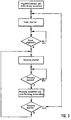
- Figure 3 shows a flow chart for sensor control.
- an LC oscillator 1 is operated with a first coil 2.
- the field strength-dependent, sinusoidal oscillator frequency f Osz is converted into a square wave signal by a suitable adaptation circuit 4 and then a frequency-voltage converter 5 supplied, whose output is connected to a subtractor 6, to which a of the instantaneous oscillator frequency f osc proportional voltage value u to u from a preset voltage target value corresponding to the ideal nominal frequency f to the oscillator corresponds, is subtracted.
- the reference frequency f ref of the oscillator is the frequency which the oscillator 1 in the unloaded state, ie in the absence of said target field H e, assumes in its operating point, where H E of the called component to be measured, the magnetic field in the coil longitudinal direction.
- the difference between the two voltage values u soll and u ist is fed to a controller 7, which adjusts the operating current 1 for the compensation coil 3 in such a way that the voltage difference (u soll - u ist ) approaches zero and the change caused by the measuring field H E the inductance 2 and the resulting change in the oscillator frequency f Osz is compensated, whereby the oscillator frequency f Osz remains more or less constant depending on the control speed of the control loop.
- the amplitude of the operating current 1 for the compensation coil 3 is directly proportional to the strength of the component of the measuring field H E in the longitudinal direction of the coil and thus changes in the same way as the strength of the measuring field.
- the actual measured variable can therefore be derived directly by evaluating the amplitude of the operating current 1.
- the operating current I flowing through the compensation coil 3 is conducted via a shunt resistor 10 to ground GND in order to make the current I evaluable as a voltage signal.
- the voltage signal is fed to an analog-digital converter 12 for further processing via a filter element 11 designed as a low-pass filter, which is carried out in a downstream control unit, not shown in this figure.
- Parasitic current components are interfering factors that result from the fact that the alternating field of the LC oscillator 1 is not ideal, but is, due to the circuit design of the oscillator, superimposed by a DC component that results from an unavoidable cross current in the oscillator 1.
- the actuations 8 and 13 are controlled by the control unit, not shown in this figure.
- FIG. 1 now shows the proposed measurement setup in simplified form, whereby for a magnetic field sensor Mx, My and Mz is provided in each spatial direction.
- each magnetic field sensor should consist of a coil arrangement, as in Figure 2 is shown.
- the ferromagnetically biased measuring coil 2 can do this be wound with the compensation coil 3, but both coils remain electrically isolated from each other. It is advantageous to run the coils in opposite directions to wrap.
- the operating circuit BS which corresponds to the circuit structure according to FIG 2 corresponds, the changeover switch pairs 9a, 9b and 14a, 14b are so formed that the actuators 8 and 13, the magnetic field sensors Mx, My and Mz cyclically with the control electronics of the operating circuit BS get connected.
- the operations 8 and 13 are in a fixed Clock from a control unit ⁇ C by a microcontroller or a other logic unit is realized, controlled. You can programmatically Switching states at output circuits of the microcontroller, whereby the changeover switch pairs 9a, 9b and 14a, 14b in a defined position to be brought.
- the proposed procedure now brings the first magnetic field sensor Mx in operative connection with the operating circuit. Then in one determined clock a number of n measured values recorded and over the A / D converter 12 is supplied to the control unit .mu.C, which is the mean calculated and stored in a memory Sp assigned to it.
- the control unit ⁇ C then switches the direction of energization in the Measuring coil 2 and the compensation coil 3 around and again takes one determined number of m measured values, with the same as before described, the procedure is followed. This is done with the Magnetic field sensors My and possibly Mz repeated before again Measured values are recorded by the first magnetic field sensor Mx.
- Figure 3 goes into an advantageous embodiment of the measurement routine.
- the control unit ⁇ C first selects a magnetic field sensor and determines the measuring direction for this. Then a timer is started. After this has expired, the actual measurement begins by forwarding measured values recorded with the magnetic field sensor to the control unit ⁇ C.
- the evaluation of the measured values in the control unit ⁇ C begins after the completion of the sensory measured value acquisition and consists first of all of determining the mean value from the measured values just acquired and storing the calculated mean value.
- the control unit ⁇ C selects the magnetic field sensor and the measuring direction for a further measurement value acquisition and outputs a control signal to the actuations 8 and 13 for the switching means 9a, 9b and 14a, 14b.
- the measurement is repeated, it is not necessary to start the timer first, since the measuring arrangement is still in the steady state. Therefore, immediately after the query as to whether the measuring process should be started, the command for its execution can follow. If the control unit ⁇ G, however, one of the parameters Magnetic field sensor "or If the measuring direction "changes, the measuring arrangement must first be prepared for the measurement, which also includes starting the timer. In the manner described here, all the existing magnetic field sensors are processed one after the other. Then the measuring cycle begins again.
Landscapes
- Physics & Mathematics (AREA)
- Engineering & Computer Science (AREA)
- Radar, Positioning & Navigation (AREA)
- Remote Sensing (AREA)
- General Physics & Mathematics (AREA)
- Electromagnetism (AREA)
- Condensed Matter Physics & Semiconductors (AREA)
- Measuring Magnetic Variables (AREA)
- Navigation (AREA)
Applications Claiming Priority (2)
| Application Number | Priority Date | Filing Date | Title |
|---|---|---|---|
| DE19729896 | 1997-07-12 | ||
| DE19729896A DE19729896A1 (de) | 1997-07-12 | 1997-07-12 | Vorrichtung zur Ermittlung der magnetischen Feldstärke des Erdmagnetfeldes, insbesondere in einer Fahrzeugnavigationseinrichtung |
Publications (3)
| Publication Number | Publication Date |
|---|---|
| EP0890847A2 true EP0890847A2 (fr) | 1999-01-13 |
| EP0890847A3 EP0890847A3 (fr) | 2001-08-22 |
| EP0890847B1 EP0890847B1 (fr) | 2004-09-22 |
Family
ID=7835491
Family Applications (1)
| Application Number | Title | Priority Date | Filing Date |
|---|---|---|---|
| EP98112436A Expired - Lifetime EP0890847B1 (fr) | 1997-07-12 | 1998-07-04 | Dispositif pour la détermination du champ magnétique terrestre, en particulier dans un système de navigation véhiculaire |
Country Status (4)
| Country | Link |
|---|---|
| EP (1) | EP0890847B1 (fr) |
| AT (1) | ATE277358T1 (fr) |
| DE (2) | DE19729896A1 (fr) |
| ES (1) | ES2229419T3 (fr) |
Families Citing this family (1)
| Publication number | Priority date | Publication date | Assignee | Title |
|---|---|---|---|---|
| DE10113131B4 (de) * | 2001-03-17 | 2006-11-16 | Sensitec Gmbh | Anordnung zur Messung der magnetischen Feldstärke oder von örtlichen Differenzen magnetischer Feldstärken, sowie Schaltungsanordnung für die Auswerteeinheit und Verwendungen der Anordnung und der Schaltungsanordnung |
Family Cites Families (3)
| Publication number | Priority date | Publication date | Assignee | Title |
|---|---|---|---|---|
| JPH0493781A (ja) * | 1990-08-10 | 1992-03-26 | Seiko Instr Inc | 三次元積分磁束計 |
| US5644851A (en) * | 1991-12-20 | 1997-07-08 | Blank; Rodney K. | Compensation system for electronic compass |
| DE4237365A1 (de) * | 1992-11-05 | 1994-05-11 | Mannesmann Kienzle Gmbh | Verfahren und Anordnung zur Speicherung von Meßdaten in einem Registriergerät |
-
1997
- 1997-07-12 DE DE19729896A patent/DE19729896A1/de not_active Withdrawn
-
1998
- 1998-07-04 AT AT98112436T patent/ATE277358T1/de not_active IP Right Cessation
- 1998-07-04 ES ES98112436T patent/ES2229419T3/es not_active Expired - Lifetime
- 1998-07-04 EP EP98112436A patent/EP0890847B1/fr not_active Expired - Lifetime
- 1998-07-04 DE DE59811981T patent/DE59811981D1/de not_active Expired - Fee Related
Also Published As
| Publication number | Publication date |
|---|---|
| ES2229419T3 (es) | 2005-04-16 |
| ATE277358T1 (de) | 2004-10-15 |
| DE19729896A1 (de) | 1999-01-14 |
| EP0890847B1 (fr) | 2004-09-22 |
| EP0890847A3 (fr) | 2001-08-22 |
| DE59811981D1 (de) | 2004-10-28 |
Similar Documents
| Publication | Publication Date | Title |
|---|---|---|
| EP1114326B1 (fr) | Compteur electrique et module d'entree pour compteur electrique | |
| DE10142305B4 (de) | Vorrichtung zur Erfassung einer Versetzung | |
| DE4344290C2 (de) | Axialer Positionsdetektor für eine Stange | |
| DE3741734A1 (de) | Vorrichtung zur messung der elektromagnetischen werte einer spule, insbesondere zur messung der ankerstellung eines spulen/anker-magnetsystems | |
| DE4103933C2 (de) | Verfahren zum Feststellen der Position eines beweglichen Bauteils und Schaltung für einen Positionssensor | |
| EP0071873A2 (fr) | Circuit pour détecter des objets au moyen d'une boucle conductrice | |
| EP2265964B1 (fr) | Procédé et dispositif de mesure du courant dans des lignes de phase | |
| EP0693674B1 (fr) | Appareil pour déterminer la position d'un objet linéairement mobil, avec un transformateur de mesure | |
| DE2917013A1 (de) | Vorrichtung zum messen des profils eines metallischen koerpers | |
| DE2634425A1 (de) | Verfahren und einrichtung zur messung der position einer magnetischen stange | |
| DE2636586C3 (de) | Einrichtung zur Messung einer im wesentlichen linearen Verschiebung eines Körpers mit einer festen Spule | |
| DE3040316C2 (de) | Verfahren und Vorrichtung zur kontaktlosen Messung von Gleich- und Wechselströmen, insbesondere von Strom-Augenblickswerten | |
| DE2545325C3 (de) | Schaltungsanordnung zur Messung des Isolationswiderstandes erdfreier Starkstromschaltungen | |
| DE69132528T2 (de) | Koordinateneingabegerät basierend auf dem Mateucci-Effekt | |
| DE10004080C1 (de) | Sensorvorrichtung und Verfahren zur Erzeugung eines Ausgangssignals einer Sensorvorrichtung | |
| DE69607158T2 (de) | Abfragegerät für ein identifizierungssystem | |
| EP0890847B1 (fr) | Dispositif pour la détermination du champ magnétique terrestre, en particulier dans un système de navigation véhiculaire | |
| DE102017128472B4 (de) | Induktiver Näherungsschalter und Verfahren zum Betreiben eines induktiven Näherungsschalters | |
| DE69029711T2 (de) | Schaltungsanordnung zur Steuerung eines Freikolbenmotors, insbesondere eines Kühlschrankkompressors | |
| DE2520031C3 (de) | Vorrichtung zum Bestimmen magnetischer Zylinderdomänen | |
| DE102019214941A1 (de) | Verfahren und Ermittlungseinrichtung zum Ermitteln einer Zustandsgröße eines Magnetaktors zu einem bestimmten Zeitpunkt | |
| DE19826673C2 (de) | Prüfgerät und Prüfverfahren für Elektrizitätszähler | |
| EP0046317B1 (fr) | Procédé et dispositif pour détecter la direction d'un court-circuit | |
| EP0228579B1 (fr) | Tablette à digitaliser ainsi que son procédé de commande | |
| DE10106941A1 (de) | Phasen- und Frequenznachlaufsynchronisationsschaltungen |
Legal Events
| Date | Code | Title | Description |
|---|---|---|---|
| PUAI | Public reference made under article 153(3) epc to a published international application that has entered the european phase |
Free format text: ORIGINAL CODE: 0009012 |
|
| AK | Designated contracting states |
Kind code of ref document: A2 Designated state(s): AT BE CH CY DE DK ES FI FR GB GR IE IT LI LU MC NL PT SE |
|
| AX | Request for extension of the european patent |
Free format text: AL;LT;LV;MK;RO;SI |
|
| PUAL | Search report despatched |
Free format text: ORIGINAL CODE: 0009013 |
|
| AK | Designated contracting states |
Kind code of ref document: A3 Designated state(s): AT BE CH CY DE DK ES FI FR GB GR IE IT LI LU MC NL PT SE |
|
| AX | Request for extension of the european patent |
Free format text: AL;LT;LV;MK;RO;SI |
|
| 17P | Request for examination filed |
Effective date: 20011013 |
|
| AKX | Designation fees paid |
Free format text: AT BE CH DE ES FR GB LI NL SE |
|
| RAP1 | Party data changed (applicant data changed or rights of an application transferred) |
Owner name: SIEMENS AKTIENGESELLSCHAFT |
|
| 17Q | First examination report despatched |
Effective date: 20020725 |
|
| GRAP | Despatch of communication of intention to grant a patent |
Free format text: ORIGINAL CODE: EPIDOSNIGR1 |
|
| GRAS | Grant fee paid |
Free format text: ORIGINAL CODE: EPIDOSNIGR3 |
|
| GRAA | (expected) grant |
Free format text: ORIGINAL CODE: 0009210 |
|
| AK | Designated contracting states |
Kind code of ref document: B1 Designated state(s): AT BE CH DE ES FR GB LI NL SE |
|
| REG | Reference to a national code |
Ref country code: GB Ref legal event code: FG4D Free format text: NOT ENGLISH |
|
| REG | Reference to a national code |
Ref country code: CH Ref legal event code: EP |
|
| REF | Corresponds to: |
Ref document number: 59811981 Country of ref document: DE Date of ref document: 20041028 Kind code of ref document: P |
|
| REG | Reference to a national code |
Ref country code: CH Ref legal event code: NV Representative=s name: SIEMENS SCHWEIZ AG |
|
| REG | Reference to a national code |
Ref country code: SE Ref legal event code: TRGR |
|
| GBT | Gb: translation of ep patent filed (gb section 77(6)(a)/1977) |
Effective date: 20050126 |
|
| REG | Reference to a national code |
Ref country code: ES Ref legal event code: FG2A Ref document number: 2229419 Country of ref document: ES Kind code of ref document: T3 |
|
| PLBE | No opposition filed within time limit |
Free format text: ORIGINAL CODE: 0009261 |
|
| STAA | Information on the status of an ep patent application or granted ep patent |
Free format text: STATUS: NO OPPOSITION FILED WITHIN TIME LIMIT |
|
| ET | Fr: translation filed | ||
| 26N | No opposition filed |
Effective date: 20050623 |
|
| PGFP | Annual fee paid to national office [announced via postgrant information from national office to epo] |
Ref country code: ES Payment date: 20080729 Year of fee payment: 11 Ref country code: DE Payment date: 20080722 Year of fee payment: 11 Ref country code: CH Payment date: 20080715 Year of fee payment: 11 |
|
| PGFP | Annual fee paid to national office [announced via postgrant information from national office to epo] |
Ref country code: NL Payment date: 20080716 Year of fee payment: 11 Ref country code: FR Payment date: 20080715 Year of fee payment: 11 Ref country code: AT Payment date: 20080715 Year of fee payment: 11 |
|
| PGFP | Annual fee paid to national office [announced via postgrant information from national office to epo] |
Ref country code: GB Payment date: 20080722 Year of fee payment: 11 |
|
| PGFP | Annual fee paid to national office [announced via postgrant information from national office to epo] |
Ref country code: SE Payment date: 20080714 Year of fee payment: 11 Ref country code: BE Payment date: 20080814 Year of fee payment: 11 |
|
| REG | Reference to a national code |
Ref country code: CH Ref legal event code: PCAR Free format text: SIEMENS SCHWEIZ AG;INTELLECTUAL PROPERTY FREILAGERSTRASSE 40;8047 ZUERICH (CH) |
|
| BERE | Be: lapsed |
Owner name: *SIEMENS A.G. Effective date: 20090731 |
|
| REG | Reference to a national code |
Ref country code: CH Ref legal event code: PL |
|
| EUG | Se: european patent has lapsed | ||
| GBPC | Gb: european patent ceased through non-payment of renewal fee |
Effective date: 20090704 |
|
| NLV4 | Nl: lapsed or anulled due to non-payment of the annual fee |
Effective date: 20100201 |
|
| REG | Reference to a national code |
Ref country code: FR Ref legal event code: ST Effective date: 20100331 |
|
| PG25 | Lapsed in a contracting state [announced via postgrant information from national office to epo] |
Ref country code: LI Free format text: LAPSE BECAUSE OF NON-PAYMENT OF DUE FEES Effective date: 20090731 Ref country code: FR Free format text: LAPSE BECAUSE OF NON-PAYMENT OF DUE FEES Effective date: 20090731 Ref country code: CH Free format text: LAPSE BECAUSE OF NON-PAYMENT OF DUE FEES Effective date: 20090731 |
|
| PG25 | Lapsed in a contracting state [announced via postgrant information from national office to epo] |
Ref country code: GB Free format text: LAPSE BECAUSE OF NON-PAYMENT OF DUE FEES Effective date: 20090704 |
|
| PG25 | Lapsed in a contracting state [announced via postgrant information from national office to epo] |
Ref country code: DE Free format text: LAPSE BECAUSE OF NON-PAYMENT OF DUE FEES Effective date: 20100202 Ref country code: BE Free format text: LAPSE BECAUSE OF NON-PAYMENT OF DUE FEES Effective date: 20090731 Ref country code: AT Free format text: LAPSE BECAUSE OF NON-PAYMENT OF DUE FEES Effective date: 20090704 |
|
| REG | Reference to a national code |
Ref country code: ES Ref legal event code: FD2A Effective date: 20090706 |
|
| PG25 | Lapsed in a contracting state [announced via postgrant information from national office to epo] |
Ref country code: ES Free format text: LAPSE BECAUSE OF NON-PAYMENT OF DUE FEES Effective date: 20090706 |
|
| PG25 | Lapsed in a contracting state [announced via postgrant information from national office to epo] |
Ref country code: SE Free format text: LAPSE BECAUSE OF NON-PAYMENT OF DUE FEES Effective date: 20090705 |
|
| PG25 | Lapsed in a contracting state [announced via postgrant information from national office to epo] |
Ref country code: NL Free format text: LAPSE BECAUSE OF NON-PAYMENT OF DUE FEES Effective date: 20100201 |