EP0891014A2 - Dispositif de détection de verrouillage d'un connecteur - Google Patents
Dispositif de détection de verrouillage d'un connecteur Download PDFInfo
- Publication number
- EP0891014A2 EP0891014A2 EP98112489A EP98112489A EP0891014A2 EP 0891014 A2 EP0891014 A2 EP 0891014A2 EP 98112489 A EP98112489 A EP 98112489A EP 98112489 A EP98112489 A EP 98112489A EP 0891014 A2 EP0891014 A2 EP 0891014A2
- Authority
- EP
- European Patent Office
- Prior art keywords
- detecting
- lock
- projections
- arms
- locking arm
- Prior art date
- Legal status (The legal status is an assumption and is not a legal conclusion. Google has not performed a legal analysis and makes no representation as to the accuracy of the status listed.)
- Withdrawn
Links
- 230000002452 interceptive effect Effects 0.000 claims abstract description 16
- 229920003002 synthetic resin Polymers 0.000 description 4
- 239000000057 synthetic resin Substances 0.000 description 4
- 238000005452 bending Methods 0.000 description 3
- 238000001514 detection method Methods 0.000 description 3
- 238000003780 insertion Methods 0.000 description 3
- 230000037431 insertion Effects 0.000 description 3
- 230000007423 decrease Effects 0.000 description 1
Images





Classifications
-
- H—ELECTRICITY
- H01—ELECTRIC ELEMENTS
- H01R—ELECTRICALLY-CONDUCTIVE CONNECTIONS; STRUCTURAL ASSOCIATIONS OF A PLURALITY OF MUTUALLY-INSULATED ELECTRICAL CONNECTING ELEMENTS; COUPLING DEVICES; CURRENT COLLECTORS
- H01R13/00—Details of coupling devices of the kinds covered by groups H01R12/70 or H01R24/00 - H01R33/00
- H01R13/64—Means for preventing incorrect coupling
- H01R13/641—Means for preventing incorrect coupling by indicating incorrect coupling; by indicating correct or full engagement
Definitions
- the present invention generally relates to a connector and more particularly, to a lock-detecting connector which is capable of surely detecting incomplete or complete connection of connectors.
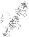
- FiG.13 shows a prior art lock-detecting connector disclosed in Japanese Patent Application Laid-open No.3-285280 (hereinafter "JP '280").
- the lock-detecting connector 61 consists of a male connector 62, a female connector 63, and a lock-detecting member 64, made of synthetic resin, installed on the male connector 62.
- the connectors 62,63 are made up of connector housings 65,66 made of synthetic resin and housing-accommodated terminals 67,68 (FIG.14), respectively.
- a resilient locking arm 69 having a locking portion 70 at the upper-end is provided on the male connector housing 65.
- a receiving portion 71 relative to the locking arm 69 is provided on the female connector housing 66, and an downwardly-facing fixed engaging projection 72 (FIG.14) relative to the locking portion 70 is provided in the receiving portion 71.
- the lock-detecting member 64 has a forwardly extending resilient detecting arm 73.
- An engaging projection 74 is formed at the upper-end of the detecing arm 73.
- the detecting arm 73 is slidingly inserted along the locking arm 69.
- the engaging projection 74 can abut on the locking portion 70.
- FIGS.14A to 14D show operation of the above lock-detecting connector.
- the end of the locking arm 69 abuts on the fixed engaging projection 72 on the female connector 63, and then the Iocking arm 69 bends inwardly integrally with the detecting arm 73 as shown in FIG.14B.
- the lock-detecting member 64 can not be further pushed into since the engaging projection 74 is abutting on the locking portion 70, thereby detecting incomplete connection.
- the locking portion 70 on the locking arm 69 goes over the engaging projection 72 on the female connector 63 and engages the engaging projection 72.
- the engaging projection 74 on the detecting arm 73 slides under both of the engaging projection 72 and the locking portion 70 by pushing the lock-detecting member 64, thereby completing insertion of the detecting member 64.
- an object of the present invention is to provide a lock-detecting connector which exhibits sure detectability of semi-connection and complete connection of connectors.
- the present invention provides a lock-detecting connector consisting of: a male connector having a resilient locking arm and a pair of protecting walls on both sides of the locking arm; a female connector having
- the present invention provides the lock-detecting connector a slit for receiving the outwardly-facing projection is provided on each of the protecting walls and an upwardly-facing projection capable of abutting on the protecting wall is provided on each of the detecting arms.
- the present invention provides the lock-detecting connectors wherein an interfering portion is provided on a lower portion of a rear end of the locking arm, and a pair of first-stop projections to abut on the locking arm in its bent-state and a second-stop projection to about on the interfering portion are provided on the lock-detecting member.
- the present invention provides the lock-detecting connector wherein provisional engaging arms are provided between the detecting arms and the first-stop projections, and engagement portions engaging with the provisional engaging arms are provided on the male connector.
- the pair of detecting arms in a semi-connected state of the connectors, that is, in a state of the locking arm being bent, the pair of detecting arms abut on the pair of protecting walls, thereby making the detecting arms stable and preventing the detecting arms from bending or getting rickety, and therefore sure detection of the semi-connected state can be performed.
- the outwardly-facing projections enter the slits by being pushed by the front corner-portions of the female connector, the detecting arms functions with a slight inward-bending, thereby enabling smooth pushing-operation of the lock-detecting member and also smooth connecting operation of the connectors.
- the lock-detecting member provisionally engages the male connector at the vertical middle thereof, thereby enabling stable and smooth pushing-operation of the lock-detecting member.
- the lock-detecting connector 1 of this embodiment is made up of a male connector 2, a female connector 3, and a lock-detecting member 4 of synthetic resin attached to the male connector 2.
- a male connector housing 5 and a female connector housing 6 each made of synthetic resin is eliminated.
- a resilient locking arm 7 supported at both ends ifs formed on top of the male connector housing 5.
- the locking arm 7 has a plate-like arm-body portion 9 with a locking projection 8 and a press-operating portion 10 highly constructed from the arm-body portion 9.
- Pairs of protecting walls (guide walls) 12,12, and 20,20 are provided respectively on both sides of the arm-body portion 9 and of the operating portion 10.
- the protecting walls 12,20 extend from a housing top wall 13.
- a short slit 14 is formed at the foot of each protecting wall 12 and a guide projection 15 relative to the lock-detecting member 4 is also formed in be middle of the housing top wall 13.
- the slit 14 is slightly higher than an outwardly-facing projection 17 on a detecting arm 16 of the lock-detecting member 4. Height of the outwardly-facing projection 17 is equal to thickness of the detecting arm 16.
- a rectangular-like notched recess 18 is formed at the rear half of the operating portion 10 and a pair of slender resilient connecting portions 19, which are supported by columns formed integrally with the respective protecting walls 20, are disposed on both sides of the notched recess 18.
- a rectangular block-like interfering portion 22 is formed integrally with the operating portion 10 on the lower side thereof The interfering portion 22 has a penetrated hole 23.
- tapered guide surfaces 24 relative to the lock-detecting member 4 are formed inside the pair of columns 21, tapered guide surfaces 24 relative to the lock-detecting member 4, engagement step-portions (engagement portions) 25 continuing the tapered guide surfaces 24, and big and small guide grooves 26,27 both under the tapered guide surfaces 24 are formed.
- the lock-detecting member 4 is inserted into an accommodating space 28 formed with the notched recess 18 on the housing top wall 13.
- the lock-detecting member 4 has a pair of detecting arms 16,16 projecting long from both sides of a base portion 30 in an insertion direction (front), a pair of provisional engaging arms 32,32 disposed over the detecting arms 16 and projecting forwardly from both sides of a rear wall (press-operating wall) 31, a pair of first-stop projections (stoppers) 33,33 disposed over the provisional engaging arms 32 and projecting forwardly from both sides of the rear wall 31, and a second-stop projection (stopper) 34 projecting forwardly from the lateral center of the base portion 30.
- the detecting arm 16 has the outwardly-facing projection 17 at the end-outside for sliding use and has an upwardly-facing projection 36 at the end-top for abutting use.
- the outwardly-facing projection 17 has a guide tapered-surface 17a.
- the upwardly-facing projection 36 is formed in a substantially rectangular block-like shape on the detecting arm 16 and has a large abutting surface 36a at the end.
- the abutting surface 36a is capable of abutting on a rear end (upper side of the slit 14) 12a of the protecting wall 12.
- the provisional engaging arm 32 extends to be middle of the detecting arm 16 and has a provisional engaging projection 38 at the end-outside.
- the provisional engaging projection 38 can engage the engagement step-portion 25 along the tapered guide surface 24.
- the first-stop projection 33 is formed in a rectangular columnlike, projects a little shorter than be provisional engaging arm 32, and has an abutting surface 33a at the end.
- the abutting surface 33a can abut against a rear end surface 10a on both sides of the press-operating portion 10.
- a second-stop projection 34 is formed in a rectangular block-like shape, projects with the same length as the first-stop projection 33, has a height up to the middle of the provisional engaging arm 32, and has an abutting surface 34a at the end-top.
- the abutting surface 34a can abut against a lower portion of the interfering portion 22.
- a front end 40a of be upper wall 40 is located facing the rear end 10a of the operating portion 10, and the vertical wall 39 is located facing the interfering portion 22.
- a pair of small stopping projections 41 are formed on the both sides. The stopping projections 41 engage be guide grooves 27 and are capable of abutting on the end of be grooves 27.
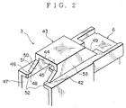
- a hood portion 43 capable of accommodating the arm-body portion 9 of the locking arm 7 and the protecting walls 12 on a top wall 42 of the female connector housing 6.
- the top wall 42 has a notched opening under the hood portion 43 in a connector connecting-direction.
- a engaging projection (engaging portion) 44 relative to the locking projection 8 of be locking arm 7 is provided inside the hood portion 43 at the front end thereof, and a guide projection 45 is provided in the hood portion 43 at the same level as the top wall 42.
- the guide projection 45 can proceed between the protecting walls 12.
- the notched opening (notched portion) 46 communicates with a connector-connecting chamber 47 located below.
- Inwardly-facing sectional walls 48 on both sides of the notched opening 46 extend in parallel to ahood rear wall 49. From the front end of hood side-walls 53 to the front end of the housing top wall 42, triangle-like ribs 50 are formed. Inner surface 51 of the hood portion 43 with the rib 50 and be inwardly-facing sectional wall 48 of the notched opening 46 are on the same plane. At the front end of both of the inwardly-facing sectional walls 48, corner-portions (front corner-portions) 52 to push the outwardly-facing projections 17 of the detecting arms 16 are formed. The front corner-portions 52 each have a small tapered section. The outwardly-facing projections 17 can slide from the corner-portions 52 along the inwardly-facing sectional walls 48 of the notched opening 46.
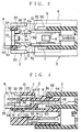
- the lock-detecting member 4 is provisionally engaged with be male connector 2. More specifically, the outwardly-facing projections 38 of the provisional engaging arms 32 proceed along the respective tapered guide surfaces 24, while the arms 32 bend inwardly, and the projections 38 engage the engagement step-portions 25.
- the outwardly-facing projections 17 of the detecting arms 16 project outwardly from the respective protecting walls 12.
- the stopping projections 41 of the detecting member 4 proceed to entrances of the respective guide grooves 27 (FIG.1).
- the female connector 3 makes an initial-connection with the male connector 2, a front tapered surface 8a on the locking projection 8 of the locking arm 7 abutting on another front tapered surface 44a on the engaging projection 44 of the hood portion 43.
- Outer surfaces of the protecting walls 12 slide on inner surface of the hood portion 43.
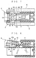
- the locking arm 7 is still in a downwardly-bent state, and the connectors 2,3 are in semi-connection (FIG.8).
- the detecting member 4 cannot proceed since the stop projections 33,34 of be detecting member 4 abut the rear end surface 10a and the interfering portion 22 both on the operating portion 10 caused by downwardly bending the operating portion 10 of be locking arm 7.
- the pair, right and left, of first-stop projections 33,33 abut on the rear both sides of the operating portion 10, and the second-stop projection 34 at the center abuts on lower portion of the interfering portion 22 of the operating portion 10.
- a penetrated hole 23 of the operating portion 10 has no operative relation with be projections 33.
- Sufficient detectability i.e. abutting force
- the three stop projections 33,34 are arrange on vertexes of a triangle, which enables stable detection.
- the outwardly-facing projections 17 on be detecting arms 16 have slightly deeply entered along the inwardly-facing sectional wall 48 in the notched opening 46 of the female connector housing 6.
- the front ends of the detecting arm 16 are located nearer the center in partially contact with the rear ends 12a of the protecting walls 12, thereby enabling the outwardly-facing projections 17 and the arm front ends 16a to enter the respective slits 14(FIG.9).
- the detecting member 4 can be inserted in a completely connected state of the connectors.
- the air of the detecting arms 16,16 proceed along both sides of the guide projection 15 inside the hood portion 43.
- the outwardly-facing projections 17 enter the slits 14 of the protecting walls 12, and the upwardly-facing projections 36 proceed along inner surfaces of the protecting walls 12.
- the inwardly-facing sectional walls 48 (FIG.2) of the female connector housing 6 are positioned on the outsides of the outwardly-facing projections 17, the inwardly-facing sectional walls 48 (FIG.2) of the female connector housing 6 are positioned.
- the stopping projections 41 abut on the ends of be guide grooves 27 (FIG.1), the front end 40a of the upper wall 40 of the detecting member 4 abuts on the rear end 10a of the operating portion 10 of the locking arm 7, and the vertical wall 39 abuts on the interfering portion 22.
- the outwardly-facing projections 17 are pushingly in contact with the inwardly-facing sectional walls 48 in be notched opening 46, thereby holding the detecting member 4 without coming-off This enables to eliminate a final engaging means, therefore, no releasing operation of the means is required.
- the detecting member 4 can be easily drawn back and return to a provisionally engaged state by lightly pulling the upper wall 40 with a nail.
- the outwardly-facing projections 17 on the detecting arms 16 may be pushed by the front corner-portions 52 in the notched opening 46 and the projections 17 may slide along the inner surfaces of the protecting walls 12 by an operation of pushing the detecting member 4, without forming both of the slits 14 on the protecting walls 12 and the upwardly-facing projections 36 on the detecting arms 16. In this case, however, a deflection of the detecting arms 16 and force for pushing them increase.
Landscapes
- Details Of Connecting Devices For Male And Female Coupling (AREA)
Applications Claiming Priority (3)
| Application Number | Priority Date | Filing Date | Title |
|---|---|---|---|
| JP18221997 | 1997-07-08 | ||
| JP9182219A JPH1126089A (ja) | 1997-07-08 | 1997-07-08 | ロック検知コネクタ |
| JP182219/97 | 1997-07-08 |
Publications (2)
| Publication Number | Publication Date |
|---|---|
| EP0891014A2 true EP0891014A2 (fr) | 1999-01-13 |
| EP0891014A3 EP0891014A3 (fr) | 1999-11-03 |
Family
ID=16114434
Family Applications (1)
| Application Number | Title | Priority Date | Filing Date |
|---|---|---|---|
| EP98112489A Withdrawn EP0891014A3 (fr) | 1997-07-08 | 1998-07-06 | Dispositif de détection de verrouillage d'un connecteur |
Country Status (3)
| Country | Link |
|---|---|
| US (1) | US6109955A (fr) |
| EP (1) | EP0891014A3 (fr) |
| JP (1) | JPH1126089A (fr) |
Cited By (6)
| Publication number | Priority date | Publication date | Assignee | Title |
|---|---|---|---|---|
| EP1113537A3 (fr) * | 1999-12-27 | 2002-02-13 | Sumitomo Wiring Systems, Ltd. | Connecteur |
| EP1207591A3 (fr) * | 2000-11-17 | 2003-07-02 | Fci | Connecteur à fiche avec un mécanisme de rétention secondaire |
| DE10335647B4 (de) * | 2002-08-08 | 2008-04-17 | Sumitomo Wiring Systems, Ltd., Yokkaichi | Verbinder, Verbinderanordnung und Verfahren zum Verbinden eines Verbinders |
| EP2211427A3 (fr) * | 2000-11-17 | 2010-08-11 | Fci | Connecteur à fiche avec un mécanisme de rétention secondaire |
| CN110612644A (zh) * | 2017-05-01 | 2019-12-24 | J.S.T.公司 | 连接器位置保证装置、连接器系统以及用于操作连接器系统的方法 |
| CN113140936A (zh) * | 2020-01-16 | 2021-07-20 | 矢崎总业株式会社 | 连接器 |
Families Citing this family (35)
| Publication number | Priority date | Publication date | Assignee | Title |
|---|---|---|---|---|
| JP3427782B2 (ja) * | 1999-05-28 | 2003-07-22 | 住友電装株式会社 | コネクタ |
| JP2001291557A (ja) | 2000-04-06 | 2001-10-19 | Sumitomo Wiring Syst Ltd | コネクタ |
| JP3708419B2 (ja) * | 2000-09-22 | 2005-10-19 | 矢崎総業株式会社 | ロック保障機構付きコネクタ |
| JP3800312B2 (ja) * | 2000-10-31 | 2006-07-26 | 住友電装株式会社 | コネクタ |
| US6514098B2 (en) * | 2000-12-28 | 2003-02-04 | Tyco Electronics Corporation | Electrical connector with terminal and connector position assurance devices |
| USD459311S1 (en) | 2001-02-14 | 2002-06-25 | J.S.T. Mfg. Co., Ltd. | Connector housing |
| JP3976134B2 (ja) * | 2001-09-05 | 2007-09-12 | 矢崎総業株式会社 | 半嵌合防止コネクタ |
| US6705886B1 (en) * | 2003-01-23 | 2004-03-16 | Fci Americas Technology, Inc. | Electrical connector having connector position assurance member |
| US6811424B2 (en) | 2003-03-26 | 2004-11-02 | Fci Americas Technology, Inc. | Electrical connector having connector position assurance member |
| US6921279B2 (en) * | 2003-06-05 | 2005-07-26 | Fci Americas Technology, Inc. | Electrical connector with connector position assurance member |
| US6857892B2 (en) * | 2003-06-05 | 2005-02-22 | Fci Americas Technology, Inc. | Electrical connector with connector position assurance member |
| US6964579B2 (en) * | 2003-06-06 | 2005-11-15 | Fci Americas Technology, Inc. | Position assured connector |
| JP4133922B2 (ja) * | 2004-04-28 | 2008-08-13 | 日本圧着端子製造株式会社 | ハウジング組立体及びこれを用いた一対の電気コネクタ |
| US7232329B1 (en) * | 2006-07-05 | 2007-06-19 | Hon Hai Precision Ind. Co., Ltd. | Cable connector assembly with unitary latch |
| US7399195B2 (en) * | 2006-12-06 | 2008-07-15 | J.S.T. Corporation | Connector position assurance device and connector assembly incorporating the same |
| CN200982591Y (zh) * | 2006-12-06 | 2007-11-28 | 鸿富锦精密工业(深圳)有限公司 | 指示灯固定结构 |
| US7470138B1 (en) * | 2007-07-18 | 2008-12-30 | J.S.T. Corporation | Connector position assurance device and connector assembly apparatus incorporating the same |
| KR101452456B1 (ko) | 2008-07-25 | 2014-10-21 | 한국단자공업 주식회사 | 커넥터 |
| US7682181B1 (en) * | 2008-09-09 | 2010-03-23 | Tyco Electronics Corporation | Latch securing member |
| JP5682066B2 (ja) * | 2011-03-11 | 2015-03-11 | 矢崎総業株式会社 | コネクタ |
| JP5751196B2 (ja) * | 2012-03-09 | 2015-07-22 | 住友電装株式会社 | コネクタ |
| US8920187B2 (en) * | 2012-03-09 | 2014-12-30 | Sumitomo Wiring Systems, Ltd. | Connector and connector assembly |
| US8926355B2 (en) * | 2012-06-29 | 2015-01-06 | Lear Corporation | Connector position assurance device for a connector assembly |
| CN203707455U (zh) * | 2013-10-30 | 2014-07-09 | 泰科电子(上海)有限公司 | 电连接器 |
| JP6517500B2 (ja) * | 2014-12-01 | 2019-05-22 | 矢崎総業株式会社 | コネクタ |
| JP6347228B2 (ja) * | 2015-05-11 | 2018-06-27 | 住友電装株式会社 | コネクタ |
| JP6515825B2 (ja) * | 2016-01-21 | 2019-05-22 | 住友電装株式会社 | コネクタ |
| JP6569131B2 (ja) * | 2016-04-26 | 2019-09-04 | 株式会社オートネットワーク技術研究所 | 嵌合検知機能を有する電気接続装置 |
| JP6370341B2 (ja) * | 2016-07-21 | 2018-08-08 | 矢崎総業株式会社 | コネクタ |
| US10454209B2 (en) | 2017-05-01 | 2019-10-22 | J.S.T. Corporation | Connector position assurance device, a connector apparatus having male and female connector assemblies with connector position assurance device, a male connector assembly, a female connector assembly, and a method for assembling the connector apparatus |
| US10355414B1 (en) | 2018-02-08 | 2019-07-16 | Delphi Technologies, Llc | Connector with a connector position assurance device |
| JP2020080270A (ja) * | 2018-11-14 | 2020-05-28 | 住友電装株式会社 | コネクタ |
| DE102019113491A1 (de) * | 2019-05-21 | 2020-11-26 | Te Connectivity Germany Gmbh | Gehäuse für einen Stecker mit einer Anzeigeeinrichtung |
| JP7837663B2 (ja) * | 2022-06-30 | 2026-03-31 | 矢崎総業株式会社 | コネクタユニット |
| JP7901509B2 (ja) * | 2022-11-09 | 2026-08-06 | ヒロセ電機株式会社 | 電気コネクタ |
Family Cites Families (8)
| Publication number | Priority date | Publication date | Assignee | Title |
|---|---|---|---|---|
| JPH0433666Y2 (fr) * | 1988-05-13 | 1992-08-12 | ||
| JP2537302B2 (ja) * | 1990-03-01 | 1996-09-25 | 矢崎総業株式会社 | 電気コネクタのロック確認装置 |
| US5217390A (en) * | 1990-04-16 | 1993-06-08 | Sumitomo Wiring Systems, Ltd. | Connector |
| GB2249438B (en) * | 1990-10-08 | 1995-01-18 | Sumitomo Wiring Systems | Connector |
| JP2571310B2 (ja) * | 1990-12-14 | 1997-01-16 | 矢崎総業株式会社 | コネクタのロック保障機構 |
| EP0655807A3 (fr) * | 1993-11-30 | 1995-12-13 | Whitaker Corp | Dispositif pour assurer la position du connecteur. |
| US5507666A (en) * | 1993-12-28 | 1996-04-16 | Yazaki Corporation | Lock securing mechanism for connectors |
| JP2907373B2 (ja) * | 1994-05-10 | 1999-06-21 | 矢崎総業株式会社 | コネクタのロック結合検知構造 |
-
1997
- 1997-07-08 JP JP9182219A patent/JPH1126089A/ja not_active Withdrawn
-
1998
- 1998-07-06 EP EP98112489A patent/EP0891014A3/fr not_active Withdrawn
- 1998-07-07 US US09/110,461 patent/US6109955A/en not_active Expired - Fee Related
Cited By (11)
| Publication number | Priority date | Publication date | Assignee | Title |
|---|---|---|---|---|
| EP1113537A3 (fr) * | 1999-12-27 | 2002-02-13 | Sumitomo Wiring Systems, Ltd. | Connecteur |
| US6439915B2 (en) | 1999-12-27 | 2002-08-27 | Sumitomo Wiring Systems, Ltd. | Connector |
| EP1207591A3 (fr) * | 2000-11-17 | 2003-07-02 | Fci | Connecteur à fiche avec un mécanisme de rétention secondaire |
| EP2211427A3 (fr) * | 2000-11-17 | 2010-08-11 | Fci | Connecteur à fiche avec un mécanisme de rétention secondaire |
| DE10335647B4 (de) * | 2002-08-08 | 2008-04-17 | Sumitomo Wiring Systems, Ltd., Yokkaichi | Verbinder, Verbinderanordnung und Verfahren zum Verbinden eines Verbinders |
| CN110612644A (zh) * | 2017-05-01 | 2019-12-24 | J.S.T.公司 | 连接器位置保证装置、连接器系统以及用于操作连接器系统的方法 |
| CN110612644B (zh) * | 2017-05-01 | 2021-08-06 | J.S.T.公司 | 连接器位置保证装置、连接器系统以及用于操作连接器系统的方法 |
| CN113140936A (zh) * | 2020-01-16 | 2021-07-20 | 矢崎总业株式会社 | 连接器 |
| EP3852205A1 (fr) * | 2020-01-16 | 2021-07-21 | Yazaki Corporation | Connecteur |
| US11309663B2 (en) | 2020-01-16 | 2022-04-19 | Yazaki Corporation | Connector |
| CN113140936B (zh) * | 2020-01-16 | 2023-03-14 | 矢崎总业株式会社 | 连接器 |
Also Published As
| Publication number | Publication date |
|---|---|
| US6109955A (en) | 2000-08-29 |
| EP0891014A3 (fr) | 1999-11-03 |
| JPH1126089A (ja) | 1999-01-29 |
Similar Documents
| Publication | Publication Date | Title |
|---|---|---|
| US6109955A (en) | Lock-detecting connector | |
| US6116939A (en) | Connector lock mechanism | |
| US6165026A (en) | Terminal | |
| KR101025638B1 (ko) | 커넥터 | |
| US6171150B1 (en) | Connector | |
| JP3324690B2 (ja) | コネクタ | |
| KR0137831B1 (ko) | 접속확인기구를 가진 접속기 조립체 | |
| EP1104051B1 (fr) | Connecteur | |
| US10404022B2 (en) | Terminal of electrical connector having spring durability | |
| US6679739B2 (en) | Terminal fitting, a connector provided therewith and use thereof | |
| US7462070B2 (en) | Connector having lock mechanism | |
| JP2002184502A (ja) | 電気コネクタ | |
| US6626701B2 (en) | Connector | |
| JP3638095B2 (ja) | 端子不完全挿入検知構造 | |
| US20070123088A1 (en) | Electrical connector | |
| JP3552192B2 (ja) | コネクタロック構造 | |
| JPH08335480A (ja) | ジョイントコネクタ、端子金具及びコネクタハウジング | |
| JPH08315927A (ja) | 低挿入力コネクタ | |
| JP2002184537A (ja) | 電気コネクタ | |
| US12592510B2 (en) | Connector having resilent portion for pressing terminal fitting | |
| JP3635629B2 (ja) | コネクタ | |
| US6589080B2 (en) | Terminal fitting and a connector | |
| JPH07335297A (ja) | コネクタ用雌端子 | |
| US20030045180A1 (en) | Connector | |
| KR100395021B1 (ko) | 모듈러 잭 |
Legal Events
| Date | Code | Title | Description |
|---|---|---|---|
| PUAI | Public reference made under article 153(3) epc to a published international application that has entered the european phase |
Free format text: ORIGINAL CODE: 0009012 |
|
| AK | Designated contracting states |
Kind code of ref document: A2 Designated state(s): BE DE ES FR GB IT SE |
|
| AX | Request for extension of the european patent |
Free format text: AL;LT;LV;MK;RO;SI |
|
| PUAL | Search report despatched |
Free format text: ORIGINAL CODE: 0009013 |
|
| AK | Designated contracting states |
Kind code of ref document: A3 Designated state(s): AT BE CH CY DE DK ES FI FR GB GR IE IT LI LU MC NL PT SE |
|
| AX | Request for extension of the european patent |
Free format text: AL;LT;LV;MK;RO;SI |
|
| 17P | Request for examination filed |
Effective date: 20000502 |
|
| AKX | Designation fees paid |
Free format text: BE DE ES FR GB IT SE |
|
| STAA | Information on the status of an ep patent application or granted ep patent |
Free format text: STATUS: THE APPLICATION IS DEEMED TO BE WITHDRAWN |
|
| 18D | Application deemed to be withdrawn |
Effective date: 20040202 |