EP0891236B1 - Lingotiere de coulee continue en charge verticale des metaux - Google Patents
Lingotiere de coulee continue en charge verticale des metaux Download PDFInfo
- Publication number
- EP0891236B1 EP0891236B1 EP97916508A EP97916508A EP0891236B1 EP 0891236 B1 EP0891236 B1 EP 0891236B1 EP 97916508 A EP97916508 A EP 97916508A EP 97916508 A EP97916508 A EP 97916508A EP 0891236 B1 EP0891236 B1 EP 0891236B1
- Authority
- EP
- European Patent Office
- Prior art keywords
- mold
- slit
- mould
- perimeter
- gas
- Prior art date
- Legal status (The legal status is an assumption and is not a legal conclusion. Google has not performed a legal analysis and makes no representation as to the accuracy of the status listed.)
- Expired - Lifetime
Links
- 238000005058 metal casting Methods 0.000 title 1
- 239000007789 gas Substances 0.000 claims abstract description 29
- 238000010926 purge Methods 0.000 claims abstract description 5
- 239000011261 inert gas Substances 0.000 claims abstract description 4
- 239000002699 waste material Substances 0.000 claims abstract 2
- 239000002184 metal Substances 0.000 claims description 26
- 229910052751 metal Inorganic materials 0.000 claims description 26
- 238000009749 continuous casting Methods 0.000 claims description 9
- 238000005192 partition Methods 0.000 claims description 6
- 229910000831 Steel Inorganic materials 0.000 claims description 4
- 239000010959 steel Substances 0.000 claims description 4
- 150000002739 metals Chemical class 0.000 claims description 3
- 238000002347 injection Methods 0.000 abstract description 17
- 239000007924 injection Substances 0.000 abstract description 17
- RYGMFSIKBFXOCR-UHFFFAOYSA-N Copper Chemical compound [Cu] RYGMFSIKBFXOCR-UHFFFAOYSA-N 0.000 abstract description 9
- 229910052802 copper Inorganic materials 0.000 abstract description 9
- 239000010949 copper Substances 0.000 abstract description 9
- 229910000881 Cu alloy Inorganic materials 0.000 abstract description 3
- XKRFYHLGVUSROY-UHFFFAOYSA-N Argon Chemical compound [Ar] XKRFYHLGVUSROY-UHFFFAOYSA-N 0.000 description 12
- 238000007711 solidification Methods 0.000 description 10
- 230000008023 solidification Effects 0.000 description 10
- 238000005266 casting Methods 0.000 description 8
- 238000009826 distribution Methods 0.000 description 8
- 229910052786 argon Inorganic materials 0.000 description 6
- 238000010408 sweeping Methods 0.000 description 4
- 239000011819 refractory material Substances 0.000 description 3
- 230000002349 favourable effect Effects 0.000 description 2
- 230000003071 parasitic effect Effects 0.000 description 2
- 230000011218 segmentation Effects 0.000 description 2
- XLYOFNOQVPJJNP-UHFFFAOYSA-N water Substances O XLYOFNOQVPJJNP-UHFFFAOYSA-N 0.000 description 2
- 230000007547 defect Effects 0.000 description 1
- 230000000593 degrading effect Effects 0.000 description 1
- 230000009977 dual effect Effects 0.000 description 1
- 230000000694 effects Effects 0.000 description 1
- 238000005516 engineering process Methods 0.000 description 1
- 238000000605 extraction Methods 0.000 description 1
- 239000012634 fragment Substances 0.000 description 1
- 239000007788 liquid Substances 0.000 description 1
- 239000000463 material Substances 0.000 description 1
- 230000005499 meniscus Effects 0.000 description 1
- 230000010355 oscillation Effects 0.000 description 1
- 230000002093 peripheral effect Effects 0.000 description 1
- 238000000926 separation method Methods 0.000 description 1
- 239000000243 solution Substances 0.000 description 1
- 125000006850 spacer group Chemical group 0.000 description 1
- 238000005507 spraying Methods 0.000 description 1
- 238000003466 welding Methods 0.000 description 1
Images
Classifications
-
- B—PERFORMING OPERATIONS; TRANSPORTING
- B22—CASTING; POWDER METALLURGY
- B22D—CASTING OF METALS; CASTING OF OTHER SUBSTANCES BY THE SAME PROCESSES OR DEVICES
- B22D11/00—Continuous casting of metals, i.e. casting in indefinite lengths
- B22D11/04—Continuous casting of metals, i.e. casting in indefinite lengths into open-ended moulds
- B22D11/0401—Moulds provided with a feed head
-
- B—PERFORMING OPERATIONS; TRANSPORTING
- B22—CASTING; POWDER METALLURGY
- B22D—CASTING OF METALS; CASTING OF OTHER SUBSTANCES BY THE SAME PROCESSES OR DEVICES
- B22D11/00—Continuous casting of metals, i.e. casting in indefinite lengths
- B22D11/04—Continuous casting of metals, i.e. casting in indefinite lengths into open-ended moulds
- B22D11/041—Continuous casting of metals, i.e. casting in indefinite lengths into open-ended moulds for vertical casting
Definitions
- the present invention relates to Continuous Load Casting Vertical of metals, especially steel.
- Continuous Casting in Vertical Load is distinguished essentially of the Classic Vertical Continuous Casting by the fact that the cooled ingot mold body (usually copper or copper alloy) ensuring the peripheral solidification of the cast metal, is surmounted by a extension in refractory material containing a reserve of molten metal maintained in the liquid state (FR-A-2000 365). In this way, the place, in the copper body, where the solidification of the cast metal begins is decoupled from that where the free surface of the molten metal is located in the enhances, while they are almost confused in Continuous Casting Classic vertical.
- the aim is to be able to pour good quality products with high extraction speeds, because the solidification zone is no longer disturbed by the usual metal flow turbulence arriving in ingot mold, which are then confined in the buffer volume within the enhances.
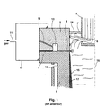
- FIG. 1 The aforementioned document describes an injection technology shown on Figure 1 attached. Essentially, it is an annular slot (8), continuous, or segmented, emerging at the inner periphery of the ingot mold.
- the scanning slot (8) is traversed by a stream of argon lost from an annular distribution chamber (13) provided at near the slot and allowing gas pressure to be maintained identical at all points of the perimeter in said room.
- Of low pressure drop pipes (12) connect this chamber (15) to the gas source consisting of a box 10 attached to the mold.
- the main pressure drop of the flow of injected gas is located at the scanning slot (8) and is closely related to the geometry thereof, and more particularly to the thickness of the slit.
- the surfaces facing each other the upper face of the cooled metal body (1) of the mold and the face of the refractory riser (2) would not be strictly parallel, a local variation of the slit thickness then leads to a heterogeneous argon injection flow rate around the periphery of the ingot mold and therefore possible surface defects on the cast product.
- the object of the present invention is to ensure an injection flow rate of gas with regular and constant sweeping around the perimeter of the mold throughout the casting operation.
- the invention relates to a casting mold Continues in Vertical Load of metals, especially steel, constituted by a cooled metallic body defining a passage for the product cast and surmounted by an extension in refractory material, and the interface of which is provided a scanning slot through which a lost inert gas stream is injected around the inside of the ingot mold, from a distribution chamber in the vicinity of the slot, and itself supplied with gas by pipes which connect it to a source of pressurized gas, an ingot mold characterized in that the slot is segmented around the perimeter of the mold using separation means which also segment said chamber distribution in contiguous compartments around the perimeter of the mold, and in that calibrated intake manifolds are provided at each compartment thus formed to connect it to the gas source under pressure.
- the invention therefore essentially consists in serve as a sweeping gas stream a non-continuous injection slot on the perimeter of the mold by a chamber which runs alongside it segmented into independent compartments around this perimeter.
- a plurality of autonomous injection circuits mounted in parallel and each comprising: a calibrated intake manifold opening into a compartment extended by a sweeping slit serving a portion of gas only around the edge of the mold, the juxtaposition of these slots according to their length ensuring gas distribution along the entire interior perimeter of the mold.
- the length of the slot coincides with that of the associated compartment.
- any disturbance of the gas flow in any circuit due to an external cause for example the accidental shrinking of a scanning slot, has no influence on the flow rate in the neighboring circuits.
- the injection perimeter around the perimeter of the mold thus becomes insensitive to local failures, unlike the prior art where a point anomaly of the scanning slit may lead to degrading the gas flow characteristics over a part perimeter significantly larger than that directly affected by the incident.
- the upper part of the body cooled metal of the ingot mold constituted, here, by a tubular element made of copper alloy energetically cooled by a circulation of water on its outer face 16, while its inner face 17 defines a space of casting in which molten steel 4 solidifies on contact with the wall cold 17 by forming a crust 15.
- This crust 15 forms an envelope which will grow inwards as the cast metal is extracted towards the bottom of the mold, until complete solidification of the product under the effect of the water spraying ramps fitted with the casting machine downstream of the mold.
- the molten metal is introduced into the mold, with a flow rate adjusted to the one with which the cast metal comes out, using a nozzle in refractory 5 opening into the bottom of a tundish, not shown, placed above.
- the nozzle is provided at its lower part side vents 6 through which the molten metal flows into the ingot mold.
- this upper part of the cast metal (15-20 cm below the meniscus) is actually a supply of molten metal contained, not in the copper body 16, but in an extension 2 made of refractory material placed on the element 16 and preferably in alignment with the inner wall 17 thereof.
- This peculiarity which is the main characteristic of a Load Casting according to the invention. Indeed, the inevitable turbulence which is the seat of the volume of metal poured into the environment of the outlet openings 6 are thus confined in the part of the casting space defined by the riser. Of the so, the solidification of the metal against the wall of cooled copper 17 begins and grows under very favorable hydrodynamic conditions, because the metal flow is of the "piston flow" type (no gradient speed sensitive in the product section).
- a stream of inert purge gas (argon) is however advised on the inside perimeter of the mold just above the edge top of the copper element where solidification begins.
- This current of scanning allows a frank and regular start of the solidification by breaking the parasitic solidification veil that can form randomly and irregularly against the refractory wall of the riser 2 and of which fragments are illustrated under the reference 14.
- this scanning current is produced by a circuit supply comprising, from an argon pressure source 10, calibrated tubing 12 connecting this source to an internal chamber 13 of distribution running around the edge of the mold and from which a slot 8 opening into the mold between the extension 2 and the body center 1.
- this slot is formed between the two aforementioned elements thanks to a spacer block 19 gauge inserted at the periphery of the copper element 1.
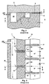
- a first chamber 20 serves to contain a volume of argon under given pressure.
- the calibrated tubes 12 connect this chamber to the second chamber 13 whose role, as we have seen, is to distribute the gas in the scanning slot 8 which opens to the inner surface 17 of the mold 1 along the periphery thereof.
- each partition 21 includes a part projection 21a of low height, corresponding to the thickness of the slot 8 in which it takes position, and a mother part 21b whose surface corresponds to the section of the chamber 13 to be partitioned.
- Each partition 21 is preferably a machined part then added, for example by welding, in chamber 13 between two arrivals of 12'-12 "calibrated pipes.
- each circuit elementary thus constituted is supplied in an identical and constant manner by the general pressure chamber 20 and the assembly becomes insensitive to local variations in slit thickness, or more generally, to any localized disturbance of the injection circuit for reasons external to the circuit.
- the calibrated tubes 12 can also be shaped like a slit.
- the intermediate chamber 13 can be indifferently formed in the refractory riser 2 (fig. 1) or in the element in copper 1 (fig. 2 and 3). Of course, it will be desirable to seal the circuits and chambers which are provided in the refractory part.
- partitions 21, which divide both the slot 8 and the room 13 it is understood that any other means than that described, fulfilling this dual function may be suitable, like platelets (equivalent 21b) of partialization of the chamber 13, associated with ribs (equivalent 21a) formed on the upper face of the element in copper and cooperating with the refractory part above to define the slits, knowing that the order of magnitude of the thickness of the slit scan can be approximately 0.1-0.3 mm.
Landscapes
- Engineering & Computer Science (AREA)
- Mechanical Engineering (AREA)
- Continuous Casting (AREA)
- Confectionery (AREA)
- Refinement Of Pig-Iron, Manufacture Of Cast Iron, And Steel Manufacture Other Than In Revolving Furnaces (AREA)
- Molds, Cores, And Manufacturing Methods Thereof (AREA)
- Separation By Low-Temperature Treatments (AREA)
Description
- la figure 1 représente, en coupe verticale, la partie supérieure d'une lingotière de Coulée Continue en Charge Verticale pourvue d'un circuit d'injection de gaz selon l'Art Antérieur déjà évoqué ;
- la figure 2 représente, également en coupe verticale selon le plan B-B' de la figure 3, une vue agrandie du circuit d'injection de gaz dont est pourvue la partie supérieure d'une lingotière de Coulée Continue en Charge Verticale conforme à l'invention ;
- la figure 3 représente le circuit d'injection vu selon le plan de coupe A-A' de la figure 1.
- à reprendre la configuration en deux chambres en cascade,
- et à sectorialiser la seconde chambre en compartiments juxtaposés selon le pourtour de la lingotière, de même que la fente de balayage associée à cette chambre.
Claims (6)
- Lingotière de Coulée Continue en Charge Verticale des métaux constituée par un corps de lingotière métallique refroidi définissant un passage pour le métal coulé et surmonté par une rehausse (2) en matériau réfractaire et à l'interface desquels est ménagée une fente de balayage (8) par laquelle un courant de gaz inerte perdu est injecté selon le pourtour intérieur de la lingotière à partir d'une chambre de répartition (13) annulaire ménagée au voisinage de ladite fente (8) et alimentée elle-même en gaz par des tubulures (12) qui la relient à une source de gaz sous pression , lingotière caractérisée en ce que la fente de balayage (8) est segmentée selon le pourtour de lingotière à l'aide de moyens de séparation (21) qui segmentent également ladite chambre de répartition (13) en compartiments (13'-13"... ) contigüs selon le pourtour de la lingotière, et en ce que des tubulures d'admission calibrées (12', 12"... ), sont prévues au niveau de chaque compartiment ainsi formé pour le relier à la source (20) de gaz sous pression.
- Lingotière selon la revendication 1, caractérisée en ce que ladite chambre de répartition (13) est ménagée dans le corps métallique refroidi (1) de la lingotière, et en ce que les moyens de séparation sont des cloisons (21) comportant une partie avancée (21a) pour la partition de la fente (8) et une partie mère (21 b) pour la partition de la chambre de répartition (13).
- Lingotière selon la revendication 1 ou 2, caractérisée en ce que la longueur de chaque portion (8'-8"... ) de fente (8) est égale à celle du compartiment (12'-12"... ) qui lui est associé.
- Lingotière selon la revendication 1, caractérisée en ce que les tubulures d'admission calibrées (12'-12"... ) sont conformées également en fente.
- Lingotière selon la revendication 1, caractérisée en ce que la fente de balayage (8) présente une épaisseur comprise entre 0.1 et 0.3 mm.
- Lingotière selon la revendication 1, caractérisée en ce qu'elle équipe une machine de Coulée Continue d'acier.
Applications Claiming Priority (3)
| Application Number | Priority Date | Filing Date | Title |
|---|---|---|---|
| FR9604306 | 1996-04-05 | ||
| FR9604306A FR2747063B1 (fr) | 1996-04-05 | 1996-04-05 | Lingotiere de coulee continue en charge verticale des metaux |
| PCT/FR1997/000546 WO1997037792A1 (fr) | 1996-04-05 | 1997-03-27 | Lingotiere de coulee continue en charge verticale des metaux |
Publications (2)
| Publication Number | Publication Date |
|---|---|
| EP0891236A1 EP0891236A1 (fr) | 1999-01-20 |
| EP0891236B1 true EP0891236B1 (fr) | 2000-03-15 |
Family
ID=9490960
Family Applications (1)
| Application Number | Title | Priority Date | Filing Date |
|---|---|---|---|
| EP97916508A Expired - Lifetime EP0891236B1 (fr) | 1996-04-05 | 1997-03-27 | Lingotiere de coulee continue en charge verticale des metaux |
Country Status (12)
| Country | Link |
|---|---|
| US (1) | US6109335A (fr) |
| EP (1) | EP0891236B1 (fr) |
| JP (1) | JP3720376B2 (fr) |
| AT (1) | ATE190530T1 (fr) |
| AU (1) | AU2513397A (fr) |
| CA (1) | CA2251020C (fr) |
| DE (1) | DE69701454T2 (fr) |
| ES (1) | ES2145594T3 (fr) |
| FR (1) | FR2747063B1 (fr) |
| GR (1) | GR3033481T3 (fr) |
| PT (1) | PT891236E (fr) |
| WO (1) | WO1997037792A1 (fr) |
Families Citing this family (5)
| Publication number | Priority date | Publication date | Assignee | Title |
|---|---|---|---|---|
| FR2787359B1 (fr) | 1998-12-18 | 2001-10-12 | Aster | Lingotiere pluriangulaire de coulee continue en charge d'un produit metallurgique |
| DE102004033917B4 (de) * | 2004-07-14 | 2008-12-24 | Schott Ag | Vorrichtung und Verfahren zum Schachtguss von stabförmigen Artikeln |
| US8393393B2 (en) | 2010-12-17 | 2013-03-12 | Halliburton Energy Services, Inc. | Coupler compliance tuning for mitigating shock produced by well perforating |
| US20120241169A1 (en) | 2011-03-22 | 2012-09-27 | Halliburton Energy Services, Inc. | Well tool assemblies with quick connectors and shock mitigating capabilities |
| US9091152B2 (en) | 2011-08-31 | 2015-07-28 | Halliburton Energy Services, Inc. | Perforating gun with internal shock mitigation |
Family Cites Families (5)
| Publication number | Priority date | Publication date | Assignee | Title |
|---|---|---|---|---|
| DE1902116A1 (de) * | 1968-01-18 | 1969-08-28 | United States Steel Corp | Verfahren und Vorrichtung zum Stranggiessen |
| CA1082875A (fr) * | 1976-07-29 | 1980-08-05 | Ryota Mitamura | Methode et appareil de coulee de premiere fusion en coquille |
| DE3533517A1 (de) * | 1985-09-20 | 1987-04-02 | Vaw Ver Aluminium Werke Ag | Verfahren und vorrichtung zum stranggiessen |
| DE4212531C1 (de) * | 1992-04-15 | 1993-10-21 | Vaw Ver Aluminium Werke Ag | Gas- und Trennmittelzuführungs- und Verteilungssystem für eine Vorrichtung zum Stranggießen |
| FR2703609B3 (fr) * | 1993-03-30 | 1995-02-10 | Lorraine Laminage | Procédé de coulée continue en charge des métaux et lingotière pour sa mise en Óoeuvre. |
-
1996
- 1996-04-05 FR FR9604306A patent/FR2747063B1/fr not_active Expired - Fee Related
-
1997
- 1997-03-27 US US09/147,028 patent/US6109335A/en not_active Expired - Lifetime
- 1997-03-27 WO PCT/FR1997/000546 patent/WO1997037792A1/fr not_active Ceased
- 1997-03-27 PT PT97916508T patent/PT891236E/pt unknown
- 1997-03-27 EP EP97916508A patent/EP0891236B1/fr not_active Expired - Lifetime
- 1997-03-27 DE DE69701454T patent/DE69701454T2/de not_active Expired - Lifetime
- 1997-03-27 JP JP53588497A patent/JP3720376B2/ja not_active Expired - Fee Related
- 1997-03-27 AU AU25133/97A patent/AU2513397A/en not_active Abandoned
- 1997-03-27 AT AT97916508T patent/ATE190530T1/de active
- 1997-03-27 ES ES97916508T patent/ES2145594T3/es not_active Expired - Lifetime
- 1997-03-27 CA CA002251020A patent/CA2251020C/fr not_active Expired - Fee Related
-
2000
- 2000-05-23 GR GR20000401178T patent/GR3033481T3/el unknown
Also Published As
| Publication number | Publication date |
|---|---|
| DE69701454D1 (de) | 2000-04-20 |
| EP0891236A1 (fr) | 1999-01-20 |
| JP2000508241A (ja) | 2000-07-04 |
| US6109335A (en) | 2000-08-29 |
| ATE190530T1 (de) | 2000-04-15 |
| GR3033481T3 (en) | 2000-09-29 |
| ES2145594T3 (es) | 2000-07-01 |
| AU2513397A (en) | 1997-10-29 |
| FR2747063B1 (fr) | 1998-05-22 |
| WO1997037792A1 (fr) | 1997-10-16 |
| JP3720376B2 (ja) | 2005-11-24 |
| FR2747063A1 (fr) | 1997-10-10 |
| CA2251020A1 (fr) | 1997-10-16 |
| CA2251020C (fr) | 2005-01-04 |
| PT891236E (pt) | 2000-07-31 |
| DE69701454T2 (de) | 2000-10-12 |
Similar Documents
| Publication | Publication Date | Title |
|---|---|---|
| FR2626508A1 (fr) | Moule de coulee de metaux, equipe d'un manchon contenant un filtre | |
| CH628260A5 (fr) | Procede de coulee de lingots. | |
| EP0891236B1 (fr) | Lingotiere de coulee continue en charge verticale des metaux | |
| EP0404641B1 (fr) | Répartiteur de coulée continue d'acier | |
| EP0989918B1 (fr) | Tete de lingotiere pour la coulee continue verticale en charge de produits metalliques a format allonge | |
| EP0743114B1 (fr) | Procédé de lubrification des parois d'une lingotière de coulée continue des métaux et lingotière pour sa mise en oeuvre | |
| EP0907439B1 (fr) | Lingotiere de coulee continue pour la coulee continue en charge verticale des metaux | |
| EP1056559B1 (fr) | Lingotiere pluriangulaire de coulee continue en charge d'un produit metallurgique | |
| EP0242347A2 (fr) | Dispositif pour la coulée d'un métal en phase pâteuse | |
| CA2251007C (fr) | Procede de coulee continue des metaux et installation de coulee pour sa mise oeuvre | |
| BE1012473A6 (fr) | Dispositif pour la coulee continue en charge verticale d'un metal en fusion. | |
| FR2618704A3 (fr) | Procede et dispositif d'alimentation d'une lingotiere de coulee continue de produits minces | |
| EP0499563B1 (fr) | Lingotière pour coulée continue de produits métalliques | |
| EP0474786A1 (fr) | Appareil d'avant-creuset d'alimentation laterale pour l'alliage et la solidification rapide de matieres en fusion | |
| EP0911096B1 (fr) | Busette de coulée pour installation de coulée continue des métaux, notamment de coulée entre cylindres | |
| FR2757430A1 (fr) | Lingotiere a largeur variable pour la coulee continue de produits metalliques | |
| FR2525131A1 (fr) | Procede et dispositif de fabrication d'un lingot d'acier creux | |
| BE1012626A3 (fr) | Dispositif pour fabriquer des produits plats par la coulee continue en charge verticale d'un metal en fusion. | |
| EP0868952B1 (fr) | Lingotière de coulée continue de métaux | |
| FR2521886A3 (fr) | Procede et dispositif pour mettre en rotation en lingotiere un metal en fusion coule en continu | |
| LU86395A1 (fr) | Dispositif et procede pour la coulee continue de l'acier | |
| FR2655578A1 (fr) | Dispositif pour la coulee continue d'une bande mince dans un champ magnetique. | |
| FR2680124A1 (fr) | Procede de coulee en source a remplissage regule et moule pour la mise en óoeuvre de ce procede. | |
| FR2711329A1 (fr) | Procédé de moulage de pièces en fonte ou en tout autre métal présentant une température de fusion élevée. | |
| FR2543031A2 (fr) | Procede et dispositif de fabrication d'un lingot d'acier creux |
Legal Events
| Date | Code | Title | Description |
|---|---|---|---|
| PUAI | Public reference made under article 153(3) epc to a published international application that has entered the european phase |
Free format text: ORIGINAL CODE: 0009012 |
|
| 17P | Request for examination filed |
Effective date: 19981105 |
|
| AK | Designated contracting states |
Kind code of ref document: A1 Designated state(s): AT BE CH DE DK ES FI FR GB GR IE IT LI LU NL PT SE |
|
| GRAG | Despatch of communication of intention to grant |
Free format text: ORIGINAL CODE: EPIDOS AGRA |
|
| 17Q | First examination report despatched |
Effective date: 19990319 |
|
| GRAG | Despatch of communication of intention to grant |
Free format text: ORIGINAL CODE: EPIDOS AGRA |
|
| GRAH | Despatch of communication of intention to grant a patent |
Free format text: ORIGINAL CODE: EPIDOS IGRA |
|
| RAP1 | Party data changed (applicant data changed or rights of an application transferred) |
Owner name: SOCIETE ANONYME DES FORGES ET ACIERIES DE DILLING Owner name: ASCOMETAL Owner name: SOLLAC (SOCIETE ANONYME) Owner name: SOGEPASS Owner name: UGINE-SAVOIE IMPHY |
|
| GRAH | Despatch of communication of intention to grant a patent |
Free format text: ORIGINAL CODE: EPIDOS IGRA |
|
| GRAA | (expected) grant |
Free format text: ORIGINAL CODE: 0009210 |
|
| AK | Designated contracting states |
Kind code of ref document: B1 Designated state(s): AT BE CH DE DK ES FI FR GB GR IE IT LI LU NL PT SE |
|
| REF | Corresponds to: |
Ref document number: 190530 Country of ref document: AT Date of ref document: 20000415 Kind code of ref document: T |
|
| REG | Reference to a national code |
Ref country code: CH Ref legal event code: EP |
|
| PGFP | Annual fee paid to national office [announced via postgrant information from national office to epo] |
Ref country code: DK Payment date: 20000320 Year of fee payment: 4 |
|
| REF | Corresponds to: |
Ref document number: 69701454 Country of ref document: DE Date of ref document: 20000420 |
|
| REG | Reference to a national code |
Ref country code: IE Ref legal event code: FG4D Free format text: FRENCH |
|
| ITF | It: translation for a ep patent filed | ||
| GBT | Gb: translation of ep patent filed (gb section 77(6)(a)/1977) |
Effective date: 20000518 |
|
| PG25 | Lapsed in a contracting state [announced via postgrant information from national office to epo] |
Ref country code: DK Free format text: LAPSE BECAUSE OF FAILURE TO SUBMIT A TRANSLATION OF THE DESCRIPTION OR TO PAY THE FEE WITHIN THE PRESCRIBED TIME-LIMIT Effective date: 20000615 |
|
| REG | Reference to a national code |
Ref country code: ES Ref legal event code: FG2A Ref document number: 2145594 Country of ref document: ES Kind code of ref document: T3 |
|
| REG | Reference to a national code |
Ref country code: PT Ref legal event code: SC4A Free format text: AVAILABILITY OF NATIONAL TRANSLATION Effective date: 20000509 |
|
| PLBE | No opposition filed within time limit |
Free format text: ORIGINAL CODE: 0009261 |
|
| STAA | Information on the status of an ep patent application or granted ep patent |
Free format text: STATUS: NO OPPOSITION FILED WITHIN TIME LIMIT |
|
| 26N | No opposition filed | ||
| REG | Reference to a national code |
Ref country code: IE Ref legal event code: FD4D |
|
| REG | Reference to a national code |
Ref country code: GB Ref legal event code: IF02 |
|
| NLT1 | Nl: modifications of names registered in virtue of documents presented to the patent office pursuant to art. 16 a, paragraph 1 |
Owner name: UGITECH Owner name: SOLLAC Owner name: SOCIETE ANONYME DES FORGES ET ACIERIES DE DILLING Owner name: SOGEPASS Owner name: ASCOMETAL |
|
| REG | Reference to a national code |
Ref country code: CH Ref legal event code: PFA Owner name: ASCOMETAL Free format text: ASCOMETAL#IMMEUBLE "LA PACIFIC", 11-13 COURS VALMY, LA DEFENSE 7#92800 PUTEAUX (FR) $ SOLLAC (SOCIETE ANONYME)#IMMEUBLE "LA PACIFIC", 11/13 COURS VALMY, LA DEFENSE 7#92800 PUTEAUX (FR) $ SOGEPASS#SITE INDUSTRIELLE DE GANDRANGE#57360 AMNEVILLE (FR) $ SOCIETE ANONYME DES FORGES ET ACIERIES DE DILLING# #66763 DILLINGEN (DE) $ UGINE-SAVOIE IMPHY#AVENUE PAUL GIROD#73400 UGINE (FR) -TRANSFER TO- ASCOMETAL#IMMEUBLE "LA PACIFIC", 11-13 COURS VALMY, LA DEFENSE 7#92800 PUTEAUX (FR) $ SOLLAC (SOCIETE ANONYME)#IMMEUBLE "LA PACIFIC", 11/13 COURS VALMY, LA DEFENSE 7#92800 PUTEAUX (FR) $ SOGEPASS#SITE INDUSTRIELLE DE GANDRANGE#57360 AMNEVILLE (FR) $ SOCIETE ANONYME DES FORGES ET ACIERIES DE DILLING# |
|
| REG | Reference to a national code |
Ref country code: FR Ref legal event code: CD |
|
| REG | Reference to a national code |
Ref country code: PT Ref legal event code: PD4A Owner name: UGITECH, FR Effective date: 20070409 |
|
| REG | Reference to a national code |
Ref country code: ES Ref legal event code: PC2A |
|
| PGFP | Annual fee paid to national office [announced via postgrant information from national office to epo] |
Ref country code: LU Payment date: 20140225 Year of fee payment: 18 |
|
| PGFP | Annual fee paid to national office [announced via postgrant information from national office to epo] |
Ref country code: CH Payment date: 20140226 Year of fee payment: 18 Ref country code: SE Payment date: 20140226 Year of fee payment: 18 Ref country code: DE Payment date: 20140220 Year of fee payment: 18 Ref country code: NL Payment date: 20140221 Year of fee payment: 18 Ref country code: FI Payment date: 20140224 Year of fee payment: 18 |
|
| PGFP | Annual fee paid to national office [announced via postgrant information from national office to epo] |
Ref country code: BE Payment date: 20140224 Year of fee payment: 18 Ref country code: ES Payment date: 20140306 Year of fee payment: 18 Ref country code: IT Payment date: 20140226 Year of fee payment: 18 Ref country code: AT Payment date: 20140225 Year of fee payment: 18 Ref country code: GR Payment date: 20140224 Year of fee payment: 18 |
|
| PGFP | Annual fee paid to national office [announced via postgrant information from national office to epo] |
Ref country code: GB Payment date: 20140226 Year of fee payment: 18 Ref country code: PT Payment date: 20140311 Year of fee payment: 18 |
|
| PGFP | Annual fee paid to national office [announced via postgrant information from national office to epo] |
Ref country code: FR Payment date: 20140328 Year of fee payment: 18 |
|
| REG | Reference to a national code |
Ref country code: FR Ref legal event code: TQ Owner name: ASCO INDUSTRIES, FR Effective date: 20141222 Ref country code: FR Ref legal event code: TQ Owner name: SOCIETE ANONYME DES FORGES ET ACIERIES DE DILL, DE Effective date: 20141222 Ref country code: FR Ref legal event code: TQ Owner name: SOGEPASS Effective date: 20141222 Ref country code: FR Ref legal event code: TQ Owner name: UGITECH, FR Effective date: 20141222 Ref country code: FR Ref legal event code: TQ Owner name: SOLLAC, FR Effective date: 20141222 Ref country code: FR Ref legal event code: GC Effective date: 20141222 |
|
| REG | Reference to a national code |
Ref country code: DE Ref legal event code: R119 Ref document number: 69701454 Country of ref document: DE |
|
| REG | Reference to a national code |
Ref country code: PT Ref legal event code: MM4A Free format text: LAPSE DUE TO NON-PAYMENT OF FEES Effective date: 20150928 |
|
| PG25 | Lapsed in a contracting state [announced via postgrant information from national office to epo] |
Ref country code: PT Free format text: LAPSE BECAUSE OF NON-PAYMENT OF DUE FEES Effective date: 20150928 Ref country code: FI Free format text: LAPSE BECAUSE OF NON-PAYMENT OF DUE FEES Effective date: 20150327 Ref country code: LU Free format text: LAPSE BECAUSE OF NON-PAYMENT OF DUE FEES Effective date: 20150327 |
|
| REG | Reference to a national code |
Ref country code: CH Ref legal event code: PL |
|
| REG | Reference to a national code |
Ref country code: AT Ref legal event code: MM01 Ref document number: 190530 Country of ref document: AT Kind code of ref document: T Effective date: 20150327 |
|
| GBPC | Gb: european patent ceased through non-payment of renewal fee |
Effective date: 20150327 |
|
| PG25 | Lapsed in a contracting state [announced via postgrant information from national office to epo] |
Ref country code: SE Free format text: LAPSE BECAUSE OF NON-PAYMENT OF DUE FEES Effective date: 20150328 |
|
| REG | Reference to a national code |
Ref country code: SE Ref legal event code: EUG |
|
| REG | Reference to a national code |
Ref country code: NL Ref legal event code: MM Effective date: 20150401 |
|
| REG | Reference to a national code |
Ref country code: GR Ref legal event code: ML Ref document number: 20000401178 Country of ref document: GR Effective date: 20151002 |
|
| PG25 | Lapsed in a contracting state [announced via postgrant information from national office to epo] |
Ref country code: IT Free format text: LAPSE BECAUSE OF NON-PAYMENT OF DUE FEES Effective date: 20150327 |
|
| REG | Reference to a national code |
Ref country code: FR Ref legal event code: ST Effective date: 20151130 |
|
| PG25 | Lapsed in a contracting state [announced via postgrant information from national office to epo] |
Ref country code: DE Free format text: LAPSE BECAUSE OF NON-PAYMENT OF DUE FEES Effective date: 20151001 Ref country code: CH Free format text: LAPSE BECAUSE OF NON-PAYMENT OF DUE FEES Effective date: 20150331 Ref country code: GR Free format text: LAPSE BECAUSE OF NON-PAYMENT OF DUE FEES Effective date: 20151002 Ref country code: LI Free format text: LAPSE BECAUSE OF NON-PAYMENT OF DUE FEES Effective date: 20150331 Ref country code: GB Free format text: LAPSE BECAUSE OF NON-PAYMENT OF DUE FEES Effective date: 20150327 |
|
| PG25 | Lapsed in a contracting state [announced via postgrant information from national office to epo] |
Ref country code: AT Free format text: LAPSE BECAUSE OF NON-PAYMENT OF DUE FEES Effective date: 20150327 Ref country code: FR Free format text: LAPSE BECAUSE OF NON-PAYMENT OF DUE FEES Effective date: 20150331 |
|
| REG | Reference to a national code |
Ref country code: ES Ref legal event code: FD2A Effective date: 20160426 |
|
| PG25 | Lapsed in a contracting state [announced via postgrant information from national office to epo] |
Ref country code: ES Free format text: LAPSE BECAUSE OF NON-PAYMENT OF DUE FEES Effective date: 20150328 |
|
| PG25 | Lapsed in a contracting state [announced via postgrant information from national office to epo] |
Ref country code: NL Free format text: LAPSE BECAUSE OF NON-PAYMENT OF DUE FEES Effective date: 20150401 |
|
| PG25 | Lapsed in a contracting state [announced via postgrant information from national office to epo] |
Ref country code: BE Free format text: LAPSE BECAUSE OF NON-PAYMENT OF DUE FEES Effective date: 20150331 |
|
| REG | Reference to a national code |
Ref country code: FR Ref legal event code: RG Effective date: 20180606 |